A method to reduce motion artifacts of sequential imaging polarimetry: Long enough exposures
minimize polarization blurs of wavy water surfaces
Á DÁM E GRI
1,2,*, G YÖRGY K RISKA
1,3, G ÁBOR H ORVÁTH
21Danube Research Institute, Centre for Ecological Research, Hungarian Academy of Sciences, Karolina út 29-31, H-1113 Budapest, Hungary
2Environmental Optics Laboratory, Department of Biological Physics, Physical Institute, ELTE Eötvös Loránd University, H-1117 Budapest, Pázmány sétány 1, Hungary
3Group for Methodology in Biology Teaching, Biological Institute, ELTE Eötvös Loránd University, H-1117 Budapest, Pázmány sétány 1, Hungary
*Corresponding author: egri.adam@okologia.mta.hu
Received 4 June 2018; revised 14 August 2018; accepted 14 August 2018; posted 15 August 2018 (Doc. ID 334425); published 10 September 2018 Researchers studying the polarization characteristics of the optical environment prefer to use sequential imaging polarimetry, because it is inexpensive and simple. This technique takes the polarization pictures through polarizers in succession. Its main drawback is, however, that during sequential exposure of the polarization pictures the target must not move, otherwise so-called motion artefacts are caused after evaluation of the polarization pictures. How could these disturbing motion artefacts be minimized? Taking inspiration from photography, our idea was to take the polarization pictures with an exposure that is long enough so that the changes of the moving/changing target can be averaged and thus motion artifacts are reduced, at least in a special case, when the motion has a stable mean. In the laboratory, we demonstrated the performance of this method when the target was a wavy water surface. We found that the errors of the measured degree and angle of polarization of light reflected from the undulating water surface decreased with increasing exposure time (shutter speed) and converged to very low values. Although various simultaneous polarimeters (taking the polarization pictures at once) are available that do not suffer from motion artifacts, our method is much cheaper and performs very well, at least when the target is a wavy water surface.
OCIS codes: (110.5405) Polarimetric imaging; (110.5200) Photography; (120.5410) Polarimetry; (120.2440) Filters; (120.5700) Reflection.
https://doi.org/10.1364/AO.57.007564
1. INTRODUCTION
The polarization characteristics of our optical environment can be effectively measured with imaging polarimetry [1-7]. This technique opens a new optical dimension, the world of polarized light for the practically polarization-blind human visual system, which can perceive only the intensity and color of light. The valuable information gained with imaging polarimetry can be used in physics, meteorology, astronomy and biology, for example. Fundamentally, there are two main kinds of imaging polarimetry: simultaneous and sequential [8].
Simultaneous imaging polarimetry (SimIP) takes the necessary polarization pictures through linear and circular polarizers at the same time [9-11]. For this task a minimum of three (plus one for circular polarization) separate optical pathways are necessary, each with its own linear/circular polarizing filter. The major disadvantage of this technique is the complexity of equipment design and thus its high cost, due to the three-four optical pathways.
Sequential imaging polarimetry (SeqIP) is much cheaper and simpler, because it has only one optical pathway into which the three- four polarizers can be somehow inserted (e.g., rotated) in succession.
Researchers studying the polarization characteristics of the optical environment prefer to use SeqIP because it is inexpensive and simple.
The main drawback of this method is that, during sequential exposure of the three-four polarization pictures, the target must not move,
otherwise so-called motion artifacts are caused by the intensity changes in certain pixels originating from local or global target movements.
In spite of this handicap of SeqIP, almost all polarization information/patterns gathered in the past decades have been measured by this technique: e.g., sky polarization [9,12-14], reflection- polarization characteristics of water surfaces [15-17], equipment used in choice experiments [18-20], and the ability to polarize of live horses, cattle and zebras [21-23]. The majority of these targets (clouds, animals, water surfaces) may move, which implies motion artifacts.
However, dealing with motion artifacts is getting more advanced [24], and it would be great practical importance if the two advantages (elimination of motion artifacts and cheapness/simplicity) of SimIP and SeqIP could somehow be combined. In this work we show an example for this.
In nature, a typical temporally changing target is an undulating water surface. The reflection-polarization characteristics of smooth, non-undulating water surfaces have been intensely studied (reviewed by [25]), because they are important in understanding the polarotactic behavior of flying water-seeking aquatic insects (reviewed by [26]).
These polarization-sensitive insects find their aquatic habitat by means of the horizontal polarization of water-reflected light in the ultraviolet or visible range of the spectrum [27-28].
As far as we know, until now mainly calm water surfaces have been measured by SeqIP. If, however, the water surface is wavy, disturbing motion artifacts occur in the patterns of the degree and angle of polarization measured by SeqIP. In addition to theoretical calculations on the polarization of wavy-water-reflected sky light [29], Harchanko and Chenault [30] studied wavy water surfaces for object detection by imaging polarimetry. They used a fast-motorized rotating-analyser SeqIP, which minimized motion artefacts. Determination of ocean wave shapes [31] or oil detection on water [32] are further interesting water-surface-related applications of imaging polarimetry, although the latter utilizes SimIP.
Taking inspiration from photographers, our idea was to take the three polarization pictures with an exposure that is long enough so that changes of the wavy water surface are averaged and thus motion artifacts are reduced. In our study we have concentrated on the measurement of linear polarization characteristics, since circularly polarized light is rare in the natural terrestrial optical environment [3].
Water surfaces differ from many other moving objects, because, during undulation, the surface periodically oscillates around a well-defined, horizontal equipotential surface. Here we show how temporal averaging with long exposures facilitates the reduction of motion artifacts of polarization patterns measured by SeqIP as a function of the shutter speed when the moving/changing target has a stable mean.
Although, sophisticated polarimeters equipped with micropolarizer arrays, being capable of providing real-time polarization information, are available on the market [10,11], the slow sequential imaging polarimeter discussed in this paper is significantly less expensive and performs remarkably well if the target is a wavy water surface.
2. MATERIALS AND METHODS
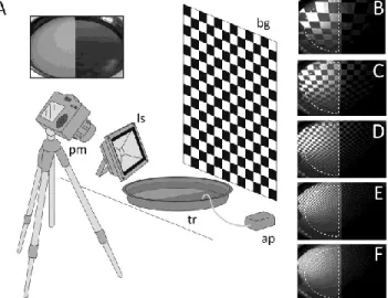
We performed imaging polarimetric measurements of a water-filled circular plastic tray (diameter = 40 cm, water depth = 4 cm) with a NIKON D3200 DSLR camera equipped with a calibrated, rotatable linear polarizer (W-Tianya Slim MC CPL). The angle of the optical axis of the polarimeter was 45° from the horizontal. One measurement consisted of taking three RAW images with different directions (α1 = 60.8°, α2 = 119.7°, α3 = 178.6° from the horizontal) of the polarizer’s transmission axis. These polarizer directions were arbitrarily chosen and were marked with notches on the rotatable polarizer. Three polarization images are enough, since the linear (non-circular) part of the Stokes vector has three parameters [3]. The linear voltage response of the CMOS pixels as a function of light intensity was verified by the Estrato Research & Development Ltd. (www.estrato.hu). Surface waves of the water in the tray were generated by the airflow of an aquarium air pump (ATMAN AT A1500) guided into the water via a plastic tube. In nature, an observer may encounter situations where the angular extension of the mirror image of field objects (e.g., trees, clouds, artificial objects) on the water surface varies in a wide range compared to that of the waves and ripples of the water surface. In order to model these situations, we used five different black and white checkered backgrounds (B1-B5), the image of which was reflected to the camera from the water surface in the tray (Fig. 1). The square size of B1, B2, B3, B4 and B5 was 9, 9/2, 9/4, 9/8 and 9/16 cm, respectively.
In the case of all five backgrounds, measurements were performed with the following 13 different shutter speeds (exposures): 1/120, 1/60, 1/30, 1/15, 1/8, 1/4, 1/2, 1, 2, 4, 8, 15, and 30 s. For each measurement of the wavy water surface, the air pump was switched off and a control measurement was performed on the smooth, calm water. Thus, the total 5 × 13 = 65 wavy measurements had their own smooth/calm counterparts to be used as control measurements. The left side of the tray bottom was painted to medium gray in order to
model a medium gray natural water surface being neither too dark, nor too bright (inset in Fig. 1A). After evaluation of each triplet of RAW polarization pictures in a masked region of the left tray half (Fig. 1B-F), the degree and angle of polarization patterns were obtained. Then, in the case of all wavy measurements the corresponding smooth/calm counterpart’s polarization patterns were subtracted, resulting in the patterns of errors Δd and Δα of the degree and angle of polarization.
The main reason for performing the polarization evaluation only on the left side was the stochastic occurrence of air bubbles on the right side where these bubbles were produced by the airflow.
The measurements were done in a laboratory under artificial unpolarized illumination of a 50 Watt, 4000 lm, cool white LED light, the intensity of which was controlled by placing neutral density (ND) filters (Lee 209, 210, 211, 298, 299 filters, Andover, UK) in front of the light source. Thus, instead of applying various ND filters on the objective lens, the intensity of illumination was controlled by creating appropriate lighting conditions for a given shutter speed. The light source illuminated the background so that no direct light hit the objective lens.
Fig. 1. (A) Schematic diagram of the experimental setup: bg, checkered black and white background; tr, plastic tray filled with water; ls, LED light source illuminating the background; pm, polarimeter; ap, air pump. The inset shows the photograph of the tray without water. (B-F) Photographs of the mirror image reflected from the water-filled tray in measurement position of the polarimeter in the case of the five different backgrounds. The dashed white half ellipse represents the masked region in which the polarization evaluations were performed.
Calculation of the average and standard deviation of the Δd- and Δα- patterns was performed for all 13 shutter speeds within the masked areas, and the following decaying exponential curve was fitted to the obtained points:
f
(s
)= a ⋅ e
−b/s+c
, (1) where a, b and c are the parameters to be fitted, and s is the shutter speed. Parameter c was used to give an estimate for the reachable minimal errors and standard deviations for d and α measured with sequential imaging polarimetry (SeqIP) of wavy water surfaces.In this model of water body, there were two components of returned light: light reflected from the water surface, and light reflected from the bottom. Because of the shallowness (4 cm water depth) and grayness (50%) of the bottom both, components contributed nearly equally to the net polarization characteristics. Our main finding, that increasing the shutter speed results in exponentially decreasing
motion artifacts, can be appropriately demonstrated by this experimental setup using such a shallow water layer.
To determine the characteristic wave period in the tray, we have recorded a video (frames per second = 50) in the same arrangement as used for imaging polarimetry. At 10 random points within the masked region (Fig. 1B-F) we obtained the pixel intensities as a function of time. After Fourier transformation of a given time series and smoothing with a 1 Hz wide window, the reciprocal of the largest frequency component was considered as the characteristic wave period for that point. Finally, we calculated the mean and standard deviation of these 10 wave periods.
Waves generated by the air pump were reflected from the tray’s wall and became superimposed on each other, so we did not examine the characteristic wavelength of the experiment. However, based on some ripples on frames of the mentioned video, we estimate that the wavelength of the initial waves were smaller than λ* = 4 cm.
3. RESULTS
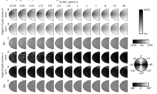
Figure 2 demonstrates the results of our imaging polarimetric measurements in the case of moderately checkered background B3 for the 13 different shutter speeds studied. Figures 2A and 2B show the patterns of the degree of polarization d of light reflected from the wavy and smooth/calm water surfaces, respectively. Figure 2C displays the patterns of the error Δd of the degree of polarization d, which is the difference of the 1st and 2nd rows in Fig. 2. Figures 2D and 2E show the patterns of the angle of polarization α of light mirrored from the wavy and smooth/calm water surfaces, while Fig. 2F displays the difference of them, namely, the patterns of the error Δα of the angle of polarization α. In the case of smooth/calm water surfaces, the patterns (Figs. 2B,E) are practically the same, independent of the shutter speed, as expected. On the other hand, the patterns of wavy water surfaces (Figs. 2A,D) show convergence to the patterns being similar to those of their smooth/calm counterparts (Figs. 2B,E) with increasing shutter
speed. Certain convergence is also obvious on the Δd and Δα patterns (Figs. 2C,F), where a significant decrease in the errors is not observable over shutter speed Sc = 1/2 s. In other words, over Sc these patterns are practically the same, close to the 50 % gray colour, which represents the zero error value. However, this convergence is not perfect, especially around the Brewster’s angle as can be seen in the centre of the Δd patterns of Fig. 2C. This is not surprising, since the degree of polarization of reflected light is maximal at the Brewster’s angle, so the corresponding error values are also higher around this viewing direction. In the case of the angle of polarization, all deviations are much smaller (Fig. 2F).
Figure 3 shows the average errors and standard deviations of the degree d and angle α of polarization for all five backgrounds as a function of the shutter speed. The understanding of these curves is facilitated by Figs. 2C and 2F. For example, the points of the curve labelled by B3 in Fig. 3A originate from averaging all pixels in Fig. 2C in case of every shutter speed. Similarly, the B3 curve in Fig. 3C is constructed by averaging the angle of polarization errors in Fig. 2F. The same principle applies for curve B3 in Figs. 3B and 3D, but here the standard deviation was calculated instead of the average. Since five different backgrounds were used for the measurements, these calculations were performed for all five backgrounds. In Fig. 3E the total average of errors Δd and Δα are shown as a function of the shutter speed, with error bars representing the standard deviation.
The total average was calculated by averaging the average errors for all backgrounds at each shutter speed. Figure 3F shows the same as Fig.
3E, but for the angle of polarization.
Figures 3G and 3H display the total average and standard deviation of Δd and Δα, respectively, with fitted decaying exponential curves (eq.
1). The average and standard deviation of Δd converges to d* = 3.88 ± 14.04%, while those of Δα converge to α* = 1.23 ± 16.76°.
According to Fourier analysis, we found that the characteristic wave period of the undulating water surface was T* = 151 ± 24 ms (mean ± standard deviation) during the measurements.
Fig. 2. Polarization patterns of the measured side of the tray in the case of background B3 as a function of the shutter speed. Degree of polarization patterns of wavy (A) and calm (B) trays. (C) Patterns of the error Δd of the degree of polarization of water-reflected light. Angle of polarization patterns of wavy (D) and calm (E) trays. (F) Patterns of the error Δα of the angle of polarization (clockwise from the vertical) of water-reflected light.
Fig. 3. Average and standard deviation (SD) of the degree and angle of polarization patterns as a function of the shutter speed and background pattern. B1-B5 indicate the checkered backgrounds with increasing spatial frequency. (A) Average of the degree of polarization error Δd. (B) Standard deviation of the degree of polarization error Δd. (C) Average of the angle of polarization error Δα. (D) Standard deviation of the angle of polarization error Δα. (E) Degree of polarization error averaged over all five backgrounds. (F) Standard deviation of the angle of polarization
calculated over all five backgrounds.
4. DISCUSSION
Our imaging polarimetric measurements were performed under controlled illumination, which is not achievable outside in nature. For taking long exposure photographs under intense illumination, photographers use ND filters to reduce the amount of light entering the camera equally at all visible wavelengths [33]. Thus ND filters should be used as attached to the objective lens. Since birefringence can occur in plastic filters, the ND filter should be placed between the objective lens and the polarizer, to avoid false polarimetric results.
As our results indicate, increasing the shutter speed (exposure) reduces the errors originating from motion artefacts. On the other hand, the whole measurement should be as quick as possible, because the global illumination may change any time due to the movement of clouds and/or the Sun, for example.
Note that the achievable minimum error d* of the degree of polarization is positive (Fig. 3G). In other words, the probability of a positive d*-value is higher than that of a negative one in a given pixel.
This is, because motion of the water surface results in intensity changes in the scene, which are interpreted as higher degrees of polarization during polarization evaluation. This is the reason that motion artefacts usually take shape in relatively high degrees of polarization, rather than low ones. In the case of the angle of polarization, the total average error α* is practically zero, independent of the shutter speed (Fig. 3H). Although, the standard deviations of α and d can be high, the total average error of the degree and particularly
the angle of polarization is close to zero for sufficiently high shutter speeds. Thus, if the experimenter is interested in the mean reflection- polarization characteristics of a region (consisting of thousands of pixels) of the scene, our measurement method is fair enough.
When polarimetrically imaging an undulating water surface, different polarization directions belong to different orientations of the wavy surface. The meaning of the degree of polarization p of water- reflected light is more complex: On the one hand it is well known that the greater the deviation of the direction of reflected light from the Brewster’s angle, the smaller is the p of surface-reflected light. Thus, lower p-values refer to viewing directions farther from Brewster’s angle. Furthermore, in natural environments the p of water-returned light depends on the water turbidity, the brightness of the bottom and the illumination conditions. In the case of clear water with a dark bottom in ambient illumination, the returned light is often highly and mainly horizontally polarized. However, if the water is turbid and illuminated by direct sunlight, the returned light can be almost unpolarized or even vertically polarized.
Our main aim was to demonstrate that an increasing shutter speed results in exponentially decreasing motion artifacts. We showed this in such a way that the degree and angle of polarization differences between a wavy and a motionless (smooth) control water surface were averaged for the whole masked surface (left half of the tray). The same exponential decrease should happen also locally if we perform this for an arbitrary angle of view. Therefore, it is unnecessary to perform a control measurement by SimIP. In our experiment,
such simultaneous polarimetry control was replaced by the sequential polarimetry of the smooth water surface.
It is well known that aquatic insects usually detect water surfaces by means of the horizontal polarization of water-reflected light [3,34-35], thus horizontally and strongly polarized light is often attractive to these insects. If an aquatic entomologist studying the polarotaxis of aquatic insects is interested in the mean degree of polarization of light reflected from undulating water surfaces, she/he can use the SeqIP method with a long enough exposure presented here. According to Figs. 2 and 3, over shutter speed Sc = 1/2 s the errors did not decrease remarkably. Taking into account the characteristic wave period (T* = 151 ± 24 ms), exposures including at least N* = 3-4 wave periods were practically sufficient for the achievable reduction of imaging polarimetric errors. However, in the case of slowly undulating natural waters these values may increase.
For reducing the motion artefacts of SeqIP of undulating water surfaces, another method might be to average multiple measurements, but this would require significantly more images, and thus would be very time-consuming. It is important to take the necessary three polarization images in the RAW mode of the camera, because (i) the bit depth of the pictures must be as high as possible and (ii) the linear response of the camera’s sensor can only be exploited in this mode. Since RAW pictures have large size, it is not optimal to perform a series of short exposures. Rather, it is worth using long exposures and storing only one triplet of RAW polarization images. A special form of the previously mentioned image stacking is used in high-dynamic-range (HDR) imaging where the problem of motion artifacts is also well known [36-38].
In the nature, in addition to undulating water surfaces, wind-blown oscillating leaves of vegetation (e.g., trees, bushes) are other examples for objects reflecting and polarizing light with a stable mean orientation/position. We have chosen a wavy water surface to test the performance of long-exposure SeqIP, because water bodies are common and thus play a central role in the visual environment.
Furthermore, their reflection-polarization characteristics are important for water-seeking polarotactic aquatic insects.
5. CONCLUSIONS
On the basis of our results we conclude the following:
(1) The errors of the measured degree and angle of polarization of light reflected from undulating water surfaces decreased with increasing exposure time (shutter speed) and converged to very low values.
(2) According to our results, the average and standard deviation of the degree and angle of polarization converges to d* = 3.88 ± 14.04 %, and α* = 1.23° ± 16.76°, respectively.
(3) Although various simultaneous polarimeters, taking the polarization pictures at once, are available that do not suffer from motion artefacts (but sometimes suffer from spatial misregistration [4]), our method is much cheaper and performs very well, at least when the target is a wavy water surface.
Funding Information. Hungarian National Research, Development and Innovation Office (NKFIH PD-115451).
Acknowledgment. This project was supported by the János Bolyai Research Scholarship of the Hungarian Academy of Sciences.
REFERENCES
1. N. Shashar, T. W. Cronin, G. Johnson, and L. B. Wolff, "Portable imaging polarized light analyzer," Proc. SPIE 2426 (1995), pp. 2426–8.
2. G. Horváth and D. Varjú, "Polarization pattern of freshwater habitats recorded by video polarimetry in red, green and blue spectral ranges and its relevance for water detection by aquatic insects," J. Exp. Biol.
200, 1155–1163 (1997).
3. G. Horváth and D. Varjú, Polarized Light in Animal Vision – Polarization Patterns in Nature (Springer: Heidelberg, Berlin, New York, 2004).
4. J. S. Tyo, D. L. Goldstein, D. B. Chenault, and J. A. Shaw, "Review of passive imaging polarimetry for remote sensing applications," Appl.
Opt. 45, 5453–5469 (2006).
5. F. Meriaudeau, M. Ferraton, C. Stolz, O. Morel, and L. Bigué,
"Polarization imaging for industrial inspection," Proc. SPIE 6813, 681308 (2008).
6. G. Horváth (editor), Polarized Light and Polarization Vision in Animal Sciences (Springer-Verlag, 2014).
7. Y. Zhao, C. Yi, S. G. Kong, Q. Pan, and Y. Cheng, "Polarization Imaging," in Multi-Band Polarization Imaging and Applications (Springer Berlin Heidelberg, 2016), pp. 13–45.
8. R. A. Chipman, “Polarimetry,” in Handbook of Optics: Fundamentals, Techniques, and Design, M. Bass, ed., 2nd ed. (Optical Society of America, McGraw-Hill, 1994), Chap. 22, pp. 22.1–22.37.
9. G. Horváth, A. Barta, J. Gál, B. Suhai, and O. Haiman, "Ground-based full- sky imaging polarimetry of rapidly changing skies and its use for polarimetric cloud detection," Appl. Opt. 41, 543–559 (2002).
10. N. J. Brock, C. Crandall, and J. E. Millerd, "Snap-shot imaging polarimeter: performance and applications," Proc. SPIE 9099, 909903 (2014).
11. X. Zhao, F. Boussaid, A. Bermak, and V. G. Chigrinov, "Thin Photo- Patterned Micropolarizer Array for CMOS Image Sensors," IEEE Photon.
Technol. Lett. 21, 805–807 (2009).
12. R. Hegedüs, S. Akesson, and G. Horváth, "Polarization patterns of thick clouds: overcast skies have distribution of the angle of polarization similar to that of clear skies," J. Opt. Soc. Am. A 24, 2347–2356 (2007).
13. B. Sipőcz, R. Hegedüs, G. Kriska, and G. Horváth, "Spatiotemporal change of sky polarization during the total solar eclipse on 29 March 2006 in Turkey: polarization patterns of the eclipsed sky observed by full-sky imaging polarimetry," Appl. Opt. 47, H1-10 (2008).
14. T. W. Cronin and J. Marshall, "Patterns and properties of polarized light in air and water," Philos. Trans. R. Soc. Lond. B Biol. Sci. 366, 619–626 (2011).
15. G. Kriska, G. Horváth, and S. Andrikovics, "Why do mayflies lay their eggs en masse on dry asphalt roads? Water-imitating polarized light reflected from asphalt attracts Ephemeroptera.," J. Exp. Biol. 201, 2273–2286 (1998).
16. D. Szaz, G. Horvath, A. Barta, B. A. Robertson, A. Farkas, A. Egri, N.
Tarjanyi, G. Racz, and G. Kriska, "Lamp-Lit Bridges as Dual Light-Traps for the Night-Swarming Mayfly, Ephoron virgo: Interaction of Polarized and Unpolarized Light Pollution," PLoS ONE 10, e0121194 (2015).
17. A. Farkas, D. Száz, Á. Egri, A. Barta, Á. Mészáros, R. Hegedüs, G.
Horváth, and G. Kriska, "Mayflies are least attracted to vertical polarization: A polarotactic reaction helping to avoid unsuitable habitats," Physiol. Behav. 163, 219–227 (2016).
18. J. Melgar, O. Lind, and R. Muheim, "No response to linear polarization cues in operant conditioning experiments with zebra finches," J. Exp.
Biol. 218, 2049–2054 (2015).
19. Á. Egri, A. Farkas, G. Kriska, and G. Horváth, "Polarization sensitivity in Collembola: an experimental study of polarotaxis in the water-surface-
inhabiting springtail Podura aquatica," J. Exp. Biol. 219, 2567–2576 (2016).
20. B. A. Robertson, D.-R. Campbell, C. Durovich, I. Hetterich, J. Les, and G.
Horváth, "The interface of ecological novelty and behavioral context in the formation of ecological traps," Behav. Ecol. 28, 1166-1175 (2017).
21. G. Horváth, M. Blahó, G. Kriska, R. Hegedüs, B. Gerics, R. Farkas and S.
Åkesson, "An unexpected advantage of whiteness in horses: the most horsefly-proof horse has a depolarizing white coat," Proc. Roy. Soc.
London B 277, 1643-1650 (2010).
22. M. Blaho, A. Egri, L. Bahidszki, G. Kriska, R. Hegedus, S. Åkesson, and G.
Horvath, "Spottier Targets Are Less Attractive to Tabanid Flies: On the Tabanid-Repellency of Spotty Fur Patterns," PLoS ONE 7, e41138 (2012).
23. K. H. Britten, T. D. Thatcher, and T. Caro, "Zebras and biting flies:
quantitative analysis of reflected light from zebra coats in their natural habitat," PLoS ONE 11, e0154504 (2016).
24. M. El Ketara and S. Breugnot, "Imaging through haze using multispectral polarization imaging method", Proc. SPIE 10655, 106550N (2018).
25. G. Horváth, Chapter 16. Polarization patterns of freshwater bodies with biological implications. pp. 333-344. In: G. Horváth (editor) Polarized Light and Polarization Vision in Animal Sciences (Springer: Heidelberg, Berlin, New York, 2014).
26. G. Horváth and Z. Csabai, Chapter 5. Polarization vision of aquatic insects. pp. 113-145. In: G. Horváth (editor) (2014) Polarized Light and Polarization Vision in Animal Sciences (Springer: Heidelberg, Berlin, New York (2014).
27. R. Schwind, "Polarization vision in water insects and insects living on a moist substrate," J. Comp. Physiol. A 169, 531-540 (1991).
28. R. Schwind, "Spectral regions in which aquatic insects see reflected polarized light," J. Comp. Physiol. A 177, 439-448 (1995).
29. G. Zhou, W. Xu, C. Niu, and H. Zhao, "The polarization patterns of skylight reflected off wave water surface," Opt. Express 21, 32549- 32565 (2013).
30. J. S. Harchanko and D. B. Chenault, "Water-surface object detection and classification using imaging polarimetry," Proc. SPIE 5888, 588815 (2005).
31. C. J. Zappa, M. L. Banner, H. Schultz, A. Corrada-Emmanuel, L. B. Wolff, and J. Yalcin, "Retrieval of short ocean wave slope using polarimetric imaging," Meas. Sci. Technol. 19, 55503 (2008).
32. A. L. Iler and P. D. Hamilton, "Detecting oil on water using polarimetric imaging," Proc. SPIE 9459, 94590P (2015).
33. B. F. Peterson, Understanding shutter speed: creative action and low- light photography beyond 1/125 second (Amphoto Books, New York, 2008).
34. R. Schwind, "A polarization-sensitive response of the flying water bugNotonecta glauca to UV light," Journal of comparative physiology 150, 87–91 (1983).
35. R. Schwind, "Evidence for true polarization vision based on a two- channel analyzer system in the eye of the water bug, Notonecta glauca," J. Comp. Physiol. A 154, 53-57 (1984).
36. T. Jinno and M. Okuda, "Motion blur free HDR image acquisition using multiple exposures," in IEEE International Conference on Image Processing (ICIP) (IEEE, 2008), pp. 1304–1307.
37. O. Gallo, N. Gelfandz, W.-C. Chen, M. Tico, and K. Pulli, "Artifact-free high dynamic range imaging," in IEEE International Conference on Computational Photography (ICCP) (IEEE, 2009), pp. 1–7.
38. O. T. Tursun, A. O. Akyüz, A. Erdem, and E. Erdem, "The State of the Art in HDR Deghosting: A Survey and Evaluation," Computer Graphics
Forum, 34, 683–707 (2015).