C H A P T E R 11
C O H E R E N C E O F T H E E L E C T R O N - P A I R Q U A N T U M I N T E R F E R E N C E
W A V E ;
11.1. E l e c t r o n - p a i r W a v e s
WE HAVE seen that in a superconductor the resistanceless current involves the motion of pairs of electrons. W h e n considering the current, each pair may be treated as a single "particle" of mass 2m and charge 2e whose velocity is that of the centre of mass of the pair. As with ordinary particles, these current carriers may be described by m e a n s of a wave. In a normal metal the conduction electrons suffer frequent scattering ac- companied by violent changes of phase and so their electron waves are coherent only over very short distances. T h e Cooper pairs in a supercon- ductor are not, however, randomly scattered and their waves remain coherent over indefinitely long distances. W e saw in Chapter 9 [eqn.
(9.12a)] that each pair may be represented by a wavefunction which we can write as
ÖÑ =
ö
â*
ñ·
Ãí *
(11.1)where Ñ is the net m o m e n t u m of the pair whose centre of m a s s is at r . T h e term e/ ( P -r ) /* has the form of a travelling wave and describes the motion of the centre of mass of the pair.
It w a s shown in § 9.3.7 that, if the current density is uniform, all the electron-pairs in a superconductor have the same m o m e n t u m and therefore have waves of the same wavelength. T h e superposition of a number of coherent waves of equal wavelength simply results in another wave with the same wavelength, so all the electron-pairs in a supercon- ductor can together be described by a single wave of a form similar to (11.1), i.e.
ØÑ =
ø â ^ - ' í *
(11.2)where É ØÑÉ2 is the density of electron-pairs and Ñ is the m o m e n t u m per pair. W e shall call this wave, describing the motion of all the electron-
153
154 INTRODUCTION TO SUPERCONDUCTIVITY
pairs, the electron-pair wave. T h e electron-pair wave retains its phase coherence over indefinitely long distances. T h i s chapter is concerned with some of the phenomena which occur as t h e result of this long-range coherence. T h e s e phenomena are analogous to the interference and diffraction effects observed with ordinary electromagnetic waves, and, because they are manifestations on a macroscopic scale of q u a n t u m behaviour, the phenomena are often referred to under the collective title of " q u a n t u m interference".
11.1.1. P h a s e o f t h e e l e c t r o n - p a i r w a v e
It is important to understand w h a t the coherence of the electron-pair wave implies. Coherence of a wave travelling through a region m e a n s that if w e know the phase and amplitude at any point w e can, from a knowledge of the wavelength and frequency, calculate the phase and amplitude at any other point. In other words, because the wave travels undisturbed, the amplitudes and relative phases at all points in the region are uniquely related by the wave equation.
L e t us rewrite the electron-pair wave (11.2) in the f o r m t
(for simplicity we consider a one-dimensional wave), and suppose that the wave frequency í is related t o the total kinetic energy Å of a Cooper pair by the familiar relation Å = hv, and that the wavelength ë is related to the m o m e n t u m Ñ of the pair's centre of m a s s by the de Brogue rela- tion ëÑ = h.
Consider a length of superconductor joining t w o points X and Y. If no current is flowing between X and F , the m o m e n t u m Ñ of the electron pairs is zero and the wavelength ë is infinite. Consequently, the phase of an electron-pair wave is the same at X as at Y.
Suppose n o w that a resistanceless current flows from X to Y. T h e electron pairs now have a m o m e n t u m Ñ and the electron-pair wave a finite wavelength ë = h/P. T h e r e will therefore be a phase difference (Äö)÷ã between the points X and Y and this phase difference remains constant in time. T h e phase difference b e t w e e n t w o points past which a plane wave is travelling is:
t In accordance with the usual convention, the time-dependent oscillatory factor e"'2'7'1 has been omitted from the expression for the wavefunction in (11.1).
Y
(Äö)÷ã = ö÷-öã= 2ð
jj-dl,
÷
where ÷ is a unit vector in the direction of the wave propagation, and dl is an element of a line joining X to Y. ( T h o u g h ÷ is, by definition, parallel to the direction of propagation, the wave itself need not propagate in a straight line. L a t e r in this chapter we shall need to consider waves travelling round a closed circular path.) N o w for the electron-pair wave ë = h/P and the pair m o m e n t u m is Ñ = 2mv> where í is the velocity of the pairs due to the current. T h e relation of í to the supercurrent density Js
is Js = \ns. 2.5. v, where ns is the density of superelectrons, and \ns is the density of electron pairs. T h e wavelength is therefore
2 _ h n*e
so the phase difference between X and Y due to the current is ã
(A<P)XY=^jjs.dl, (11.3)
X since ÷ is necessarily parallel to Js.
Because the electron-pair wave retains its coherence throughout a superconductor it should be able to produce long-range interference phenomena, and it should be possible to observe effects analogous to familiar optical interference, e.g. Fraunhofer diffraction and diffraction by a grating. As we shall see, such effects in superconductors can be demonstrated experimentally, and such demonstrations provide a con- vincing justification for treating superelectrons as waves with long-range coherence.
11.1.2. Effec t of a m a g n e t i c field
T h e phase of the electron-pair wave may be strongly affected by the presence of an applied magnetic field. W e saw in § 8.5 that in the presence of a magnetic field the m o m e n t u m ñ of particles with charge q takes the form m\ + j A , where A is the magnetic vector potential defined by curl A = B . In the case of electron pairs, Ñ = 2mv + 2eA. W e can still derive the wavelength ë from the m o m e n t u m Ñ by ë = h/P, and so, by the same argument which led to (11.3) we find that in the presence of a magnetic field, the phase difference between t w o points X and Y is
156 INTRODUCTION TO SUPERCONDUCTIVITY
11.2. T h e F l u x o i d
W e now consider the case of a supercurrent circulating around a closed path. T h e results of this section will be of importance in a later chapter.
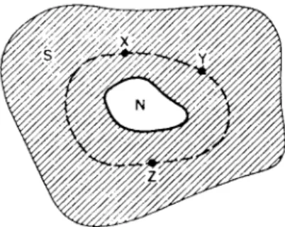
Figure 11.1 shows a superconductor enclosing a non-superconducting region N. Suppose that in Í there is a flux density  due to super- currents flowing around it (see § 2.3.1). Such a situation might arise where Í is a hole through the material or, in the case of a solid piece of superconductor, where the magnetic field generated by the encircling current maintains the region Í in the normal state.
Consider a closed path, such as the dotted curve in Fig. 11.1, which encircles the normal region. T h e r e will be a phase difference of the electron-pair wave between any t w o points on this curve, due b o t h to the presence of the magnetic field and to the circulating current. As w e have seen, the phase difference between the points X and Y is given by (11.4):
÷ ÷
< ^ W - g | l . . « + ^ j A . A ( Ð . 4 )
5 ÷ ÷
W e interpret the first term on the right-hand side as being the phase difference due to the current, and the second term as an additional phase difference due to the magnetic field. W e can therefore write
(Äø)÷ã = [(Äö)÷ãÉ + [(ÄÖ)×Õ]Â>
where [ ( Ä ^ ) ^ ]/ is the phase difference due to any current, and [(ÄÖ)×Õ\Â
is the phase difference due to any magnetic field. W e have, therefore,
[{W)xrl = jj^jh.dl
ã (11.5)S X
and
ã
[ ( Ä0 ) , Ë = ^ Ã / Á . < / 1. (11.6)
÷
T h e phase difference which can be produced b y the presence of a magnetic field plays a very important part in the phenomena which are now to be described.
FIG. 11.1. Superconductor enclosing a non-superconducting region.
N o w consider the phase change occurring around a closed path, say XYZX. T h e total phase change will be
N o w by Stokes* theorem, <f A . dl = jj curl A . J S , where dS is an ele-
s
ment of area, and furthermore curl A = B, so w e can rewrite (j>A . dl as J*J *B . dS, where S is the area enclosed by XYZX, and the phase change
s
round the closed path m a y be rewritten
W h a t follows in this chapter depends on the realization that, if the superelectrons are t o b e represented by a wave, the wave at any point can, at any instant, have only one value of phase and amplitude.
Consequently, the phase change Ä 0 around a closed path must equal 2ðç where ç is any integer. W e shall refer to this as the "phase con- dition" or " q u a n t u m c o n d i t i o n " . ! W e have therefore
^ • " • ô / ß · · " - 2 * » < m )
s
which can be rewritten
s
t T h i s condition is also responsible for the quantized electron orbits in the Bohr atom.
158 INTRODUCTION TO SUPERCONDUCTIVITY
F . and H . L o n d o n n a m e d the quantity on t h e left-hand side of this equa- tion t h e fluxoid enclosed b y t h e curve XYZX. I t is given t h e symbol Ö ' to distinguish it from the flux Ö :
Ö ' = ^ É , . Ë + { [ Â . < * 8 , ( 1 1 . 8 )
5 s
and we have shown that, because of t h e single-valuedness of the wave, the fluxoid can only exist in integral multiples of t h e unit h/2e:
Ö ' = « £ . ( 1 1 . 9 )
Note that it is sometimes convenient to write the fluxoid in the equivalent form
^
=^ j h '
d l +j
A'
d l- (
1L1°)
T h e fluxoid within a closed curve is closely related to, though not identical with, the magnetic flux within the curve. T h e first term on the right-hand side of (11.8) contains the line integral of the current density around the curve XYZX, b u t because the penetration depth is small, nearly all the circulating current will in fact b e concentrated very close to the boundary of t h e normal region N9 and this term will b e negligible un- less we are considering a curve of which a considerable part lies very close to N. T h e second term on the right-hand side of (11.8) is just the magnetic flux contained within Í and the penetration d e p t h around it.
So unless we are considering a closed curve which lies very close to the boundary of N9 the fluxoid which a curve encloses is practically t h e same as the flux it encloses.
W e see, therefore, that any flux (strictly fluxoid) contained within a superconductor should only exist as multiples of a q u a n t u m , the fluxon, Ö0, given b y
<t>Q = h/2e (11.11)
= 2 07 ÷ 1 0 ~1 5 weber.
It can be seen that this predicted value of the fluxon is extremely small.
T h e value of the fluxon h a s been measured experimentally and t h e fact that its value is found to be, as predicted, Planck's constant divided by twice the electronic charge, is strong evidence that the supercurrent is carried b y pairs of electrons.
W h a t is measured in experiments is the flux, not the fluxoid, but as w e have seen, in most cases these are indistinguishable, and the expression
"quantized flux" is often used instead of the strictly accurate "quantized fluxoid". M e a s u r e m e n t s have, for example, been m a d e of the magnetic moment of a long, hollow cylinder of superconductor which w a s repeatedly cooled below its transition temperature in very weak axial magnetic fields, À T h e thickness of the wall w a s small compared to the diameter of the central hole (though large compared to the penetration depth) and consequently the magnetic m o m e n t of the cylinder w a s proportional to the flux trapped in the hole. T h e measurements showed that the cylinder could only trap an amount of flux corresponding to an integral n u m b e r of fluxons.
Suppose a ring or hollow cylinder becomes superconducting while in an applied magnetic field. W e have seen that once the material h a s become superconducting the flux threading the hole can only be an in- tegral number of fluxons ç Ö0. However, in general, the strength of the applied field will not be such that the flux from it which threads the hole is an exact n u m b e r of fluxons, though the difference will be small because the fluxon is small. W h e n the ring becomes superconducting the strength of the circulating current which arises on the inner surface to maintain flux in the hole is just that which, together with the applied field, produces the nearest integral n u m b e r of fluxons. F o r example, if the applied field happened to produce a flux (w + | ) Ö0 in the hole, then in the superconducting state the flux in the hole will become ç Ö0. If, however, the applied field strength had been such as to produce a flux (ç + | ) Ö0 in the hole, the magnitude of the circulating current will be such as to produce a flux of (ç + 1)Ö0 (for an explanation of this see § 11.4).
Flux quantization is a special property of superconductors and does not occur in normal metals for the reason discussed in § 11.1. W e shall see that fluxons play an important role in the properties of type-II super- conductors which are discussed in the second part of this book.
11.2.1. F l u x o i d w i t h i n a s u p e r c o n d u c t i n g m e t a l
In the previous section we have been considering a closed curve which surrounds a non-superconducting region, e.g. a hole. Magnetic flux can thread this hole accompanied by a current flowing round the hole
t For example, Doll and Nabauer, Phys. Rev. Letters 7, 51 (1961). Deaver and Fairbank, ibid.
7, 43 (1961).
160 INTRODUCTION TO SUPERCONDUCTIVITY
(§ 2.3.1). T h e fluxoid enclosed within the curve will b e an integral n u m b e r ç of fluxons, b u t the value of ç will b e zero if no flux t h r e a d s the hole. If, however, w e consider a closed curve which does not encircle a non-superconducting region, so that the area enclosed b y the curve is en- tirely superconducting, then ç is always zero. T h i s will be so even if the curve passes close to a b o u n d a r y of the superconductor where, within the penetration depth, neither the flux density  nor the current density Js need b e zero. T h e m a g n i t u d e s a n d d i r e c t i o n s of  a n d J.. are everywhere such that, w h e n integrated around the curve, the t w o t e r m s contributing to the fluxoid [right-hand of (11.8)] cancel to give zero.
T h e statement t h a t the fluxoid within any closed curve not surround- ing a non-superconducting region is zero is a more precise way of expressing the perfect diamagnetism of a superconducting material, since it is valid everywhere in the metal, including the penetration depth.
11.3. W e a k L i n k s 11.3.1. J o s e p h s o n t u n n e l l i n g
Consider t w o superconductors Ñ and Q completely isolated from each other; the phase of the electron-pair wave in Ñ will be unrelated to the phase of the wave in Q. Suppose now that the gap separating the t w o pieces is gradually reduced to zero. W h e n the separation becomes very small, electron pairs can tunnel across the gap and the electron-pair waves in Ñ and Q tend to become coupled together. As Ñ and Q approach each other there is an increase in the interaction between their electrons due t o the tunnelling, and the phases of the w a v e s in the t w o pieces become progressively m o r e tightly locked together. Eventually when Ñ and Q come into contact, they form one single piece of metal and there must, under a given set of external conditions, be a definite relation between the phases throughout Ñ and Q.
Before contact is made, the interaction occurs as a result of the spread of the electron-pair wave through the gap, i.e. a tunnelling of electron pairs from Ñ and Q and vice versa. Tunnelling of an electron pair m e a n s that the t w o electrons maintain their m o m e n t u m pairing after crossing the gap. W e have already met this type of tunnelling in the previous chapter, where it w a s referred t o as "Josephson tunnelling". If the gap is thin the tunnelling across it of electron pairs is relatively probable and so an appreciable resistanceless current can flow t h r o u g h it. A gap,
however, has a critical current as does an ordinary superconductor.
W h e n resistanceless current flows across such a gap by electron-pair tunnelling there is a phase difference between the electron-pair waves on each side of the gap. It can be shown that if is is the supercurrent crossing the gap from Ñ to Q
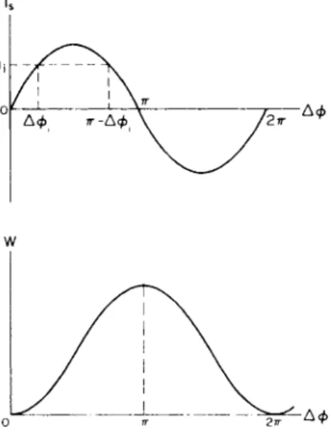
where 0Q and öÑ are the phases on each side of the gap. T h e m a x i m u m value of the supercurrent occurs when there is a phase difference of ð / 2 across the gap, and is then equals the critical current tc of the gap.
It is important to realize that, because the phase difference in (11.12) is not restricted to the range 0 to ð / 2 , the phase difference is not unique- ly determined for a given value of is b u t may take one of t w o alternative values, Ä0 or ð — Ä 0 . |
Equation (11.12) relates the electron-pair current tunnelling across a Josephson junction to the phase difference of the electron-pair wave on the t w o sides. W e saw in §§ 1.4 and 3.1 that if the supercurrent in a superconductor is varying with time, a voltage is developed across the superconductor. T h e same is true of a Josephson tunnelling junction. If the current through the junction is varying with time, the phase difference Ä 0 across it must also be changing with time, and it can be shown that a voltage V is developed across it, related to the rate of change of the phase difference by
It can be seen that this equation is consistent with equation (10.1).
Equations (11.12) and (11.13) show how the current through a Josephson tunnelling junction and any voltage which may be developed across it are related to the phase difference of the electron-pair waves on the t w o sides:
is = ic sin ( 0Q - öÑ) (11.12)
2 Ý ? Ê = Ë ^ Ä 0 . (11.13)
is = ie sin Áö (11.14.i)
2eV=h^-A(p (ll.14.ii)
+ T h e phase difference may also take on values 2ðç + Ä 0 or 2ðç + (ð — Áö) but these are not physically distinguishable from Ä 0 and ð — Ä 0 .
162 INTRODUCTION TO SUPERCONDUCTIVITY
T h e s e t w o equations are the basic equations of a Josephson tunnelling junction, and from them we can derive nearly all its properties. T h e y
follow from the coherent n a t u r e of t h e electron-pair wave in a supercon- ductor. W e do not derive t h e m in this book b u t a fairly simple derivation is given by F e y n m a n . f
11.3.2. P e n d u l u m a n a l o g u e
W e shall now show that there is a close analogy between a Josephson tunnelling junction and a simple pendulum. T h i s analogy is very useful because the m a t h e m a t i c s of Josephson junctions can b e rather c o m - plicated, and the results difficult to interpret, b u t it is often possible to visualize intuitively h o w a simple pendulum will behave and d r a w con- clusions through the analogy about t h e behaviour of a Josephson j u n c - tion. F u r t h e r m o r e , even if one cannot predict h o w a pendulum will behave under a certain set of circumstances, it is relatively easy to per- form experiments on a pendulum and obtain results which can b e transferred to a Josephson junction.
T o establish the analogy, consider the various m e c h a n i s m s by which cur- rent may flow through a Josephson junction. First there is the electron-pair tunnelling current i,. W e consider t h e general case in which this current varies with time producing, as pointed out on p . 161, a voltage F across the junction. Because there is a voltage across the junction, a current of normal (unpaired) electrons will also flow across the junction b y the normal tunnelling process. T h i s process is resistive a n d can be represented by a resistance/? across the junction [Fig. 11.2(a)]. Because the junction consists of t w o metal surfaces very close together, there is also a capacitance C across the junction. T h e three parallel b r a n c h e s in Fig. 11.2(a) therefore form the equivalent circuit of a Josephson tunnelling junction. If we p a s s a current / through the junction from an external source, this current m u s t equal the sum of the currents flowing d o w n each of the three b r a n c h e s of the equivalent circuit:
T ndV V . . A .
T o find how the total current is related to the phase difference Ä 0 across the junction, we use eqn. (ll.14.ii) to replace Vby (Ë/2Ý?×Ý//Ë )Ä0 w i t h the result that
t R. P. Feynman, Lectures on Physics, Vol. I l l , pp. 2 1 - 1 6 (Addison-Wesley).
(a) E q u i v a l e n t c i r c u i t of J o s e p h s o n junctio n is- ic ä ß ç Äö 1|—é R
I
p e n d u l u m FIG . 11.2. Pendulum analogue of a Josephson tunnelling junction.
r CH d2 A , ¹ d A , . . A .
(11.15) which is the equation relating the total current through a Josephson tunnelling junction to the phase difference of the electron-pair waves on each side.
L e t u s now consider the simple rigid pendulum of Fig. 11.2(b) which consists of a light stiff rod of length / with a bob of m a s s m at its lower end. T h e pendulum can rotate freely about the pivot P . If an external torque Ô is applied the pendulum will swing out of the vertical. L e t the angle of deflection at any instant be È. By analogy with N e w t o n ' s second law, torque produces a rate of change of angular m o m e n t u m , so if Ì is the moment of inertia of the pendulum about P ,
N o w the total torque acting on the pendulum consists of several p a r t s : there is the applied torque Ô which deflects the pendulum; this is op- posed by the weight of the bob which exerts a torque — mgl sin è and, if the pendulum is not in a vacuum and rotates with velocity dd/dt> the viscosity of the air will exert an opposing torque —çÜè/dt. So (11.16) can be written
M-rpi = total torque. (11.16)
M - j - ú = T-mglsmd-ç-j-.
Rearrangement t o bring all t e r m s in è together gives
^ .,Ü2è dd . . a
T—M-i-y + ç -j- + mgl sin È. (11.17)
164 I N T R O D U C T I O N T O S U P E R C O N D U C T I V I T Y
T h i s is the equation of rotational motion of a simple pendulum. W e can see that this equation h a s exactly the same form as equation (11.15) which relates the total current through a Josephson junction to the phase difference of the electron-pair wave on each side. A rigid pendulum is therefore an analogue of a Josephson tunnelling junction. C o m p a r i s o n of the t w o equations term by term,
(junction) / = ^ ^ Ä 0 + ^ ^ Ä 0 + ic sin Ä 0, (11.18)
(pendulum) T= Ì^- 2È + ç-^è + mgl sind (11.19) gives the following correspondence between the mechanics of the pend- ulum and the electrical properties of the junction:
Junction
Phase difference, Ä 0
T o t a l current across junction, J Capacitance, C
Normal tunnelling conductance, l/R Electron-pair tunnelling current,
is = ic sin Ä0 Voltage across junction,
Pendulum Deflection, è Applied torque, Ô M o m e n t of inertia, Ì Viscous damping, ç
Horizontal displacement of bob,
÷ = / sin è Angular velocity,
Üè
T h e s e analogues are summarized in Fig. 11.3.
As pointed out earlier, this analogue is very useful because by visualizing or experimenting on the motion of a pendulum w e can deduce the electrical behaviour of a Josephson tunnelling junction. As an exam- ple, we now investigate h o w the voltage across a junction is related t o the current through it. W e represent a gradual increase of current through the junction by a gradual increase of torque applied to the pend- ulum. W e can imagine the torque to be provided by weights hanging from a d r u m attached to the pivot of the pendulum, as in Fig. 11.3.
W h e n a small torque is applied (i.e. a small current passed through the junction) the pendulum finally settles d o w n at a constant angle of deflec-
tion È. T h e r e is then no angular velocity, so this implies that there is no voltage across a junction when a small current is passing through it, i.e.
the junction is superconducting. If the torque is gradually increased, the pendulum deflects to a greater but steady angle, i.e. we can pass more
Applie d torqu e — ^ t o t a l c u r r e n t
FlG. 11.3. Analogy between pendulum and Josephson tunnelling junction.
current through a junction without any voltage appearing. T h e r e is, however, a m a x i m u m torque which can be applied to the pendulum and which still produces a stationary deflection. T h i s is the torque which deflects the pendulum through a right angle so that it is horizontal. If we apply any greater torque the pendulum rises, accelerates upwards, passes through the vertically " u p " position, and thereafter continues to rotate continuously around its axis so long as the torque continues to b e applied. W e see, therefore, that if more than a certain "critical t o r q u e " is applied the pendulum cannot remain at rest but rotates continuously.
Because angular velocity is the analogue of voltage across a junction and the angular velocity is always in the same direction, this unstable behaviour of the pendulum shows that a d.c. voltage will appear across a junction if the current passed through it exceeds a critical value, i.e. a junction h a s a critical current.
11.3.3. a.c . J o s e p h s o n effect
L e t us consider further what can be deduced from the pendulum analogue of a Josephson tunnelling junction. Suppose that a pendulum is rotating continuously because a torque greater than the critical torque is being applied to it. As the pendulum rotates, the horizontal deflection ÷ of the bob (Fig. 11.3) oscillates, changing from right to left and back
166 INTRODUCTION TO SUPERCONDUCTIVITY
again. We have seen that the horizontal deflection of the bob cor- responds to the electron-pair current tunnelling across the junction. So the analogue tells u s that w h e n there is a d.c. voltage across a Josephson tunnelling junction an a.c. electron-pair current tunnels back and forth across it. T h i s is the a.c. Josephson effect mentioned in § 10.6. W h a t is the frequency of the a.c. tunnelling current? T o answer this we return to our pendulum analogue. W h e n a constant torque T, greater t h a n the critical torque, is applied to a pendulum, the pendulum rotates, and its rotation accelerates until the energy lost due to viscous d a m p i n g during each rotation equals the work done on the p e n d u l u m by the constant applied torque. W h e n this state is reached the period of each revolution is the same. T h e angular velocity, however, is not constant b u t varies during each revolution (on the half-cycle during which the bob is rising the rotation decelerates because gravity opposes the applied torque, but on the following half-cycle the b o b is accelerated b y gravity as it falls).
T h e frequency of the rotation is(l/2n)(dd/dt) w h e r e (dd/dt) is the time average of the angular velocity over one cycle. W e deduce, therefore, that the electron-pair tunnelling current, which is the analogue of the horizontal displacement of the p e n d u l u m ' s bob, oscillates back and forth across the junction with frequency í equal ×ï (\/2ð) {(d/ dt)/S>(p). N o w we have seen that w h e n the phase difference across a junction is varying at a rate (d/dt)N(p a voltage V appears across the junction whose instant- aneous value is (h/2e)(d/dt)&(f) [eqn. (11.14.ii)]. By analogy with the pend- ulum (d/dt)A(p always h a s the same sign but is not constant, so that the voltage V contains both d.c. and a.c. components, i.e. it is a d.c. voltage with an a.c. ripple on it. T h e average value {(Ü/Üß)Äö) of the rate of change of phase across the junction is given b y
because the d.c. component is the time average of the voltage.
Consequently the frequency of oscillation is related to the d.c. voltage across the junction by
T h e a . c Josephson effect can b e observed through the a.c. component of the voltage which appears across the junction and which can be detected b y suitable instrumentation. T h i s alternating component of the voltage causes emission of radiation with frequency í given by hv =
2eVdC. T h i s is in agreement with eqn. (10.1) derived from consideration of the energy balance of the tunnelling electron pairs.
W e may sum u p the situation as follows: when a steady direct current, greater than the critical current, is fed through a Josephson junction from a constant current source a d.c. voltage V^c appears across the junction. T h e electron-pair tunnelling current has, however, a large oscillatory component which tunnels back and forth with frequency (2e/h)Vdc across the junction. T h i s a.c. Josephson tunnelling can be observed as a voltage ripple of frequency (2e/h)V^c superimposed on the d.c. voltage.
T h e a.c. Josephson effect forms the basis of a n u m b e r of useful devices. An oscillating Josephson junction can be used as a tunable oscillator whose frequency í is given by í = 2eV/h, where V is the d.c. voltage across the junction. T h e power output is very small but its usefulness lies in the fact that the frequency can be very accurately con- trolled simply by adjusting the voltage across the junction. Josephson junctions are also used as very sensitive detectors of radiation; because an alternating electric field acting on a biased oscillating junction can drive a d.c. current through an external load.
11.3.4. C o u p l i n g e n e r g y
W e have seen that the supercurrent is tunnelling through a Josephson junction is sinusoidally related to the phase difference of the electron-
pair waves on the two sides [eqns. (11.14.i) and (11.14.U)]. If, therefore, a certain current, ix say, is passed through the junction there are t w o possible phase differences across it, Äöé and ð — Äö÷ (Fig. 11.4). W e naturally ask which of these t w o possible phase differences will in fact occur. T h e answer is determined by the fact that, as we shall now show, the energy of a Josephson tunnelling junction depends on the phase difference across it. Consider a junction through which a constant current is is being passed, the current having been raised from zero to this value over a time t. During the time the current is increasing there must be a rate of change of current di/dt, b u t eqn. (ll.14.ii) tells us that if the current through a junction is changing a voltage will appear across it, so during the time t that the current is being established there is a voltage V across the junction, and power iV is being delivered to it. So
t
work, W = j iVdty is performed in setting u p the current and the con- o
sequent phase difference across it, and W must be the increase in energy
168 INTRODUCTION TO SUPERCONDUCTIVITY
is
FIG . 11.4. Josephso n junction ; relationshi p of tunnellin g curren t i, an d energ y W to phas e differenc e Ä0.
of the junction due to the passage of a current t h r o u g h it. E q u a t i o n s (11.14.i) and (ll.14.ii) relate the voltage and current to the phase difference, and substitution of these gives the increase injunction energy as
t
ï
W = ^ [ l - c o s A 0 ] . (11.20) T h i s relationship is shown in Fig. 11.4. W e see that the energy W in-
creases with Äö for phase differences u p to ð and so, if a current ix is passed through the junction it is energetically favourable for the smaller phase difference Äö÷ to establish itself across the junction rather than the larger difference ð — Äö÷. W h e n there is no current through the junction, the phase difference across it will be zero not ð ; in t e r m s of our
pendulum analogue this is equivalent to saying that, for energetic reasons, if no torque is applied the pendulum hangs vertically d o w n w a r d s not vertically u p w a r d s .
11.3.5. W e a k - l i n k s
Josephson junctions are a special case of a more general kind of weak contact between t w o superconductors. T h e s e other forms have proper- ties similar to the Josephson tunnelling junctions we have just described.
A resistanceless current can be passed through a very narrow constric- tion or a point contact between t w o superconductors (Fig. 11.5) while a phase difference is maintained between the superconductors on each side. W e shall include all these configurations under the general name of
"weak-links". A weak-link is a region which has a m u c h lower critical current than the superconductors it joins and into which an applied magnetic field can penetrate.
( a ) Tunnellin g j u n c t i o n
(b ) C o n s t r i c t i o n ( c ) P o i n t c o n t a c t FIG. 11.5. Superconducting weak-links.
F o r all weak-links, including Josephson tunnelling junctions, the resistanceless current flowing through the link increases as the phase difference across the link increases, and the critical current is the current at which the phase difference reaches ð / 2 . However, the current is not in general proportional to the sine of the phase difference; in this respect the Josephson junction is a special case.
T h o u g h the behaviour of weak-links which are not Josephson tunnelling junctions may differ in detail from that of a Josephson tunnelling junction their general behaviour is very similar, and the effects described in this chapter for Josephson tunnelling junctions also occur for the other forms of weak-link.
Weak-links in the form of constrictions or point contacts are usually better than tunnelling junctions as radiation sources or detectors because radiation can more easily be coupled into or out of them.
170 INTRODUCTION TO SUPERCONDUCTIVITY
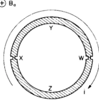
11.4. S u p e r c o n d u c t i n g Q u a n t u m I n t e r f e r e n c e D e v i c e ( S Q U I D ) W e now consider a superconducting device whose properties well illustrate the coherence of the electron-pair wave throughout a supercon- ductor and the effect of weak-links on this coherent wave. T h e device is called a superconducting quantum interference device, usually ab- breviated to " S Q U I D " . S Q U I D s can b e used to detect and measure extremely weak magnetic fields and are the basic elements of a range of very sensitive and useful instruments. T h e basic element of a S Q U I D is a ring of superconducting metal containing one or m o r e weak-links. W e shall consider here the particular form which includes t w o weak-links, as shown in Fig. 11.6. T h e ring of superconducting material h a s t w o similar weak-links X and W whose critical current ic is very m u c h less t h a n the
critical current of the rest of the ring. Because supercurrents flowing round such circuits cannot exceed the critical current of the weak-links, resistanceless currents m u s t b e very m u c h less t h a n the critical currents of the superconductors joined by the weak-links. Because of the low current density in the superconductors, the m o m e n t u m of the Cooper pairs in them is small and the corresponding electron-pair waves have a very long wavelength. T h e r e is, consequently, very little phase difference between different p a r t s of any one superconductor, and w e shall assume that this difference is negligible, so that, if there is n o applied magnetic field, the phase is the same throughout any one piece of superconductor which does not include a weak link. As a result, a phase difference appears across the superconductors only w h e n a magnetic field is applied.
W e now examine the effect of the application of a magnetic field t o a S Q U I D . In studying the behaviour of this circuit, w e shall apply t w o of the results discussed in the previous sections. First, that if a magnetic
® Ba
FIG . 11.6. Superconductin g ring with tw o weak-links .
field is applied perpendicular to the plane of the ring, it produces a difference in phase of the electron-pair wave along the p a t h XYW and along the path WZX (Fig. 11.6); we assume that the weak-links X and W are so short that the phase difference across them produced by the applied magnetic field is negligible. Second, that if a small current flows round the ring, it produces a phase difference across the weak-links, but negligible phase difference across the thick segments XYW and WZX.
Suppose that the ring has been cooled below its transition temperature in the absence of an applied magnetic field so that there is no magnetic flux threading the hole. N o w a magnetic field of gradually increasing flux density Ba is applied perpendicular to the plane of the ring. If the ring had no weak-links the application of the magnetic field would induce a current i (Fig. 11.6) which would circulate to cancel the flux in the hole.
W e shall use the convention that the clockwise direction in Fig. 11.6 h a s a positive sign. F o r the cancellation to be complete the magnitude Ii\ of the circulating current would have to be such that
L I /I = Öá (11.21)
where L is the inductance of the ring and Öá = ?/Ba, sJ being the area of the hole enclosed by the ring.
T h e presence of the weak-links h a s t w o effects:
(i) T h e y have a very small critical current *c, so any circulating current must be less than this value. Consequently, unless Ba is very small, not enough current can circulate to cancel the flux in the hole, and this flux can no longer be maintained at zero.
(ii) Even though any circulating current is limited by the weak-links to a m a x i m u m value of ic, it can nevertheless introduce a signifi- cant phase change across each of them.
T h e particular form of S Q U I D we are about to consider is con- structed so that b o t h the critical current ic of the weak-links and the inductance L of the ring are extremely small, so that
icL < Ö0. (11.22)
N o w iL is the flux generated in the hole by a circulating current, so the presence of the weak-links means that an induced circulating current cannot generate even one fluxon, and the net flux Ö in the hole is scarcely different from the flux Öá of the applied magnetic field;
172 INTRODUCTION TO SUPERCONDUCTIVITY
T h e presence of the weak-links also m e a n s that the flux within the hole is no longer necessarily an integral n u m b e r of fluxons.t However, the q u a n t u m condition that the total phase change around any closed p a t h must equal nln can still be satisfied because the circulating current, though unable to generate even one fluxon, can produce considerable phase differences across each weak-link.
Equation (11.6) tells u s that the application of a magnetic field produces a phase difference Ä 0( â ) around the ring
A 0 ( f i ) = ^ p j > A . r f l .
N o w I A . dl is the flux Öá produced in the ring by the applied magnetic field (we have seen that the flux Li produced by the circulating current is negligible, eqn. (11.22)), and h/2e equals the fluxon Ö0, so
Ä 0( â ) = 2 ô Ã ^.
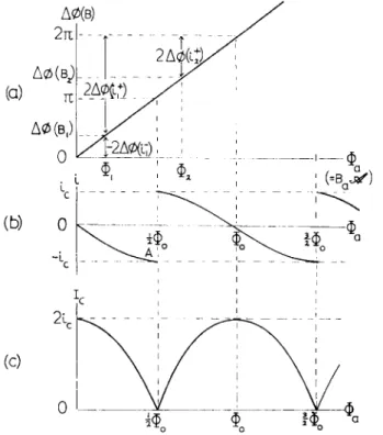
(11.23)So, when a magnetic field is applied to the superconducting ring, its effect on the electron-pair wave is to produce a phase change around the ring which is proportional to the flux of the applied field, as shown in Fig. 11.7(a). If, for example, the flux density Bx of the applied field is such that the flux threading the ring is Ö÷ (Fig. 11.7(a)), the phase change it produces around the ring is Äö(Â÷). In general the strength of the applied magnetic field will not be such as to produce an integral number of fluxons in the hole and the resulting phase change Äö{Â÷) will not equal a multiple of 2ð. However, the phase change round any closed superconducting circuit must equal an integral multiple of 2ð; a current i therefore circulates round the ring of such a strength that the additional phase different 2 Ä 0 ( é) it produces the t w o weak-links brings the total phase change round the circuit to a multiple of 2ð (Fig. 11.6):
Ä 0 ( â ) + 2 Ä 0 ( ß) = ç . 2ð. (11.24) But in an applied magnetic field producing a flux Ö, (Fig. 11.7(a)), there
are t w o possible circulating currents which could make the total phase change round the ring an integral multiple of 2ð. A current of magnitude
t In a different form of S Q U I D , which we shall not discuss, the critical current of the weak- links and the inductance are not so small. In this form of S Q U I D the flux in the hole is quantized and different from the flux of the applied field. T h i s form of S Q U I D operates in a different manner from the one discussed in this book.
FIG . 11.7. Effect of magneti c field on (a) Phas e chang e Äö(Âá) roun d rin g du e
absenc e of measurin g current .
SQUI D wit h tw o weak-link s (Lic < Ö0).
to magneti c field, (b) Circulatin g curren t i in (c) Critica l measurin g curren t Ic.
if could circulate in the clockwise direction so that the phase difference 2Ä0(*Õ) (Fig. 11.7(a)) it produces across the t w o weak-links adds on to the phase difference Äö(Â÷) produced in the two halves of the ring by the magnetic field ( n = l ) , or a smaller anticlockwise current of magnitude i\ could circulate to produce the smaller negative phase different — 2 A 0 ( / f ) which would exactly cancel the phase change due to the magnetic field (n = 0). In fact the current will circulate in the anti- clockwise direction because, as we saw in § 11.3.4, the energy of weak- links depends on the phase difference across them and, for phase differences less than ð , increases as the phase difference increases.
Therefore in our S Q U I D the smaller, anticlockwise, current is energetically favourable (because the circulating current flows through both junctions, the phase differences across them add and the phase difference across each must be less than ð ) .
W e can find how the magnitude of the circulating current depends on
174 INTRODUCTION TO SUPERCONDUCTIVITY
the strength of the applied magnetic field by m e a n s of (11.14.i) which tells us that a current i passing through a Josephson tunnelling j u n c t i o n t produces a phase different Ä 0( é) given by
â ß ç Ä 0( é) = i/ie. (11.25)
For the phase difference across the weak-links to cancel the phase difference due to the magnetic field
2 Ä 0 ( * -) - - Ä 0 ( â ) .
Substituting the values of Äö{Â) and Äö(é~) from (11.23) and (11.25) we obtain the strength of the circulating current
Ö If I = L sin ð -=4.
Öï
If the magnetic field strength is increased so that the flux through the ring approaches | Ö0 the magnitude of the anticlockwise circulating current increases as shown between Ï and A in Fig. 11.7(b). It can b e seen that when the applied field is such that the flux through the ring equals \Ö0 the circulating current reaches the critical current ic of the weak-links, so at this field strength the links go normal and the cir- culating current dies away.
Suppose the strength of the applied magnetic field is still further in- creased so that the flux Öá through the ring now h a s a value Ö2 greater than | Ö0, and the phase change Áö(Â2) it produces across the t w o halves of the ring exceeds ð (Fig. 11.7(a)). Clearly it is now energetically favourable for the total phase change to be brought u p to 2ð by a current f J circulating in the clockwise direction to produce phase changes across the weak-links which add on to those due to the magnetic field. W h e n Öá
is just greater t h a n | Ö0 the circulating current is relatively large but as the strength of the magnetic field is increased the current becomes smaller, until at Ö0 it h a s fallen to zero (Fig. 11.7(b)). It can be seen that the circulating current i varies periodically with the strength of the applied field, switching from —ic to + ic when the flux through the ring is an odd multiple of | Ö0. T h i s periodic dependence of the circulating current on the strength of an applied magnetic field is the basis of all S Q U I D s .
T In this analysis we shall assume the weak-links to be Josephson tunnelling junctions. For other weak-links, such as constrictions or point contacts, where the current is periodic in Ä0 but not sinusoidally related, a similar analysis can be carried out and leads to a qualitatively similar result.
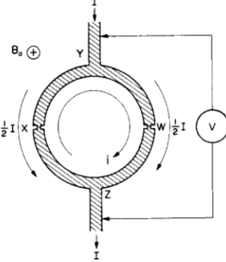
T h e period of variation of the circulating current corresponds to a flux change of one fluxon, Ö0, a very small amount of magnetic flux, so the value of the circulating current is affected by very small changes in applied magnetic field strength. If we could detect changes in the cir- culating current we should, therefore, be able to detect very small changes in the strength of the applied magnetic field, and our S Q U I D could be used as a sensitive magnetometer. W e can, as w e shall now see, detect changes in the circulating current b y passing a current / across the ring between t w o side-arms Y and Z , as shown in Fig. 11.8. W e shall
call / the "measuring current". If the ring is symmetrical, / divides equally, {/flowing through each weak-link; b u t so long as the S Q U I D is everywhere superconducting no voltage will be detected by the voltmeter
V connected across it. However, if we increase the measuring current / enough, a voltage will be developed. T h e value of measuring current / at which the voltage appears is called the critical measuring current Ic of the ring. It can be seen that current i — \l flows across one weak-link and a larger current i + {/ across the other, and it might be thought that the critical measuring current must be that which raises i + {/ to the critical value ic of the weak-link through which it flows, i.e. that the critical measuring current would be 2{tc — t). However, this is not necessarily true; in general it becomes impossible, as we shall now see, for the phase change of the electron-pair wave round the ring to equal an integral multiple of 2ð (a necessary condition for there to be a supercon-
i
I
FIG. 11.8. Superconductin g quantu m interferenc e device (SQUID) .
176 INTRODUCTION TO SUPERCONDUCTIVITY
ducting p a t h right round the ring) even though the current t h r o u g h neither weak-link h a s reached ic. T h a t is to say, a voltage appears across the ring at a measuring current Ic less t h a n 2(zc — i). T h i s is an excellent example of the fundamental importance of the coherence of the electron- pair wave in a superconductor.
W e now find the value of the critical measuring current and how it depends on the strength of the magnetic field. L e t a and â b e the phase changes produced by currents flowing across the t w o weak-links (we m u s t r e m e m b e r our sign convention: the clockwise direction is positive, so a positive phase difference is an increase in phase angle ö in a clockwise direction round the ring), and let Äö(Â) be the total phase change produced by the applied magnetic field around the top and bot- tom halves of the ring. If the ring is superconducting,
a + â + Ä 0( Â) = ç. 2ð .
Equation (11.23) gives Ä 0( Â) in t e r m s of the flux Öá enclosed b y the ring; so
i.e. a + â + 2ð^ = ç.2ð. (11.26) T h i s relation m u s t always be satisfied if there is t o be superconductivity
everywhere round the ring. T h e m a g n i t u d e s of á and â depend on the total current passing through the weak-links so, w h e n the current / is fed through the ring the circulating current i adjusts itself so that the phase condition (11.26) is still satisfied.
In the absence of the measuring current / the phase differences across the t w o weak links are equal because the same current i flows through each. F r o m (11.26) we see that in this case á = â = ð[ç — ( Öá/ Ö0) ] . But when we pass the current / , a and â are n o longer equal, because the current through X is now i — \l and t h a t t h r o u g h W is now i + \l. Since a + â must remain constant, the decrease in a m u s t equal the increase in â. L e t us write t h a t when the measuring current / is passed from Y to Æ
a = ð[ç - ( Öâ/ Ö0) ] - ü,
(11.27) â = ð[ç - ( Öá/ Ö0) ] + ä
where ä depends on the current / . If the weak-links are Josephson tunnelling junctions the phase difference across them due to current through t h e m is given b y (11.14.i), so for the weak-links X and W w e have
i— jl— tc sin
i + \I= ic sin
; ( " - | Ç ·
(11.28)
W e are interested in how the S Q U I D behaves as we increase /, so w e eliminate i b y subtraction,
/ = ic {8ß ç [ð (ç - | ? ) + ü ] - 8ß ç [ ð{ç - ^ - ü ] )
= 2ic cos
4 - ì
sino . (11.29)T h e right-hand side of this equation could have either positive or negative values, depending on whether the cos and sin t e r m s have the same or opposite signs. But we are considering what happens when the measuring current / is fed through from Y to Æ in Fig. 11.8, and we have taken / in this direction to be positive. If / t u r n s out to be negative, this is equivalent to turning the figure upside down. T h i s inversion does not, however, represent a physically different situation, so we may write (11.29) as
I=2L cos
Isin ä
I.E.
I=2L Ö
cos ð - = r ^ · sin ä (11.30) However, sin ä cannot have a magnitude greater than unity, so (11.30) can only be satisfied and all of the ring remain superconducting if
/ < 2 /c cos ð Ö
a
Therefore the critical measuring current is Ö ç Öá
cos ð Ö ç (11.31)
It can be seen from this that, when a magnetic field is applied, the critical measuring current of the S Q U I D depends in a periodic manner on the strength of the field, being a m a x i m u m when the field is such that
178 INTRODUCTION TO SUPERCONDUCTIVITY
the flux Öá through the ring is an integral n u m b e r of fluxons (Fig.
11.7(c)).
A graph such as Fig. 11.7(c), which shows the periodic variation of critical current with applied magnetic field strength, is referred to as the
"interference p a t t e r n " of the superconducting q u a n t u m interferometer.
In order to obtain a pattern such as Fig. 11.7(c) the critical current of the links and the area of the hole m u s t be small, so that Lic < Ö0 and the induced current cannot appreciably screen the hole from the applied field. Often, however, the critical currents of the links and the size of the hole may be large enough so that Lic > ã Ö0, and there is appreciable screening of the hole. It can b e shown that in this case the d e p t h of modulation (Fig. 11.9) of the critical current is reduced to ÄÉ€ = Öï/L.
_L
2<D0
Ì·ï Á HoA
Applie d magheti c fiel d strength , Ha
ìà Á
FIG. 1 1 . 9 . Interference pattern of superconducting q u a n t u m inteferometer (Lic > Ö0).
11.4.1. " D i f f r a c t i o n " e f f e c t s
W e have seen that the critical current of a S Q U I D is modulated by an applied magnetic field. It also happens, however, that the critical current of a single weak-link is modulated by a magnetic field. Although, as w e showed in the last section, a magnetic field produces negligible phase difference across the weak-links in a S Q U I D , it nevertheless h a s a con- siderable effect on their critical current. It can b e shown t h a t the critical current ic of a Josephson junction in a magnetic field parallel to the plane of the junction is itself a periodic function of t h e strength of the magnetic field, being a m i n i m u m w h e n t h e magnetic flux passing through the j u n c - tion equals an integral n u m b e r of fluxons.
Equation (11.31) gives the critical current of a S Q U I D , i.e. t w o weak- links in parallel. T h i s equation has exactly the same form as the Fraunhofer formula for the optical interference pattern from t w o parallel slits (Young's fringes) if we take Ic as equivalent to the resultant amplitude A of the optical oscillation, ic as the amplitude a of each of the two interfering b e a m s and ð Öá/ Ö0 as half the phase difference between the t w o interfering beams. T h e amplitude of Young's fringes is, however, modulated by the diffraction pattern of the individual slits. T h e Fraunhofer formula for optical diffraction from a single slit is
sin â
á = á
0 â
where â is one-half of the phase difference of rays from the t w o opposite edges of the slit. By analogy, therefore, we might expect the critical current ic of a single weak-link to depend on the magnetic field in the following w a y :
ic = ic(0) sin ( ð Ö , / Ö0)
ðÖ,,/Ö ç (11.32)
where Ö , is the flux of the applied magnetic field passing through the area of the link. In fact, a direct calculation, similar to that in the previous section, of the phase of the electron-pair wave in the neighbourhood of a weak-link leads to exactly this result.t
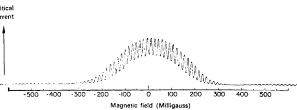
Just as optical interference patterns which are formed by a number of slits are modulated in amplitude by the diffraction which occurs at each individual slit, the interference pattern from a superconducting interferometer is modulated by the "diffraction" occurring at the weak- links. W e neglected this diffraction effect in drawing Figs. 11.7(c) and 11.9. An actual interference pattern obtained from a q u a n t u m interferometer is shown in Fig. 11.10. T h e modulation of the interference
pattern by the diffraction pattern of the weak-links is evident.
It is very difficult to make a superconducting q u a n t u m interferometer in which both weak-links have the same cross-sectional area. Conse- q u e n t l y t h e interference p a t t e r n is usually m o d u l a t e d by t w o periodicities and a complicated multiply-periodic pattern results.
W e have seen that there is a close analogy between q u a n t u m inter- ference effects in superconductors and optical interference. Never- theless, the reader should be warned against drawing false conclusions
t T h e detailed calculation may be found in Jaklevic, Lambe, Mercereau and Silver, Phys. Rev.
140A, 1628 (1965).
180 I N T R O D U C T I O N T O S U P E R C O N D U C T I V I T Y Critica l
curren t
- 5 0 0 - 4 0 0 -300 - 200 -100 0 100 200 300 4 0 0 5 0 0 Magneti c field (Milligauss )
FIG . 11.10. Trac e of interferenc e patter n fro m a quantu m interferometer , showin g modulatio n of interferenc e by diffraction . (Reproduce d b y kin d permissio n of R. C.
Jaklevic , J. Lambe , J. E. Mercereau , an d A. H . Silver , Scientifi c Laboratory , For d Moto r Company. )
from t h i s a n a l o g y a b o u t t h e n a t u r e of s u p e r c o n d u c t i n g q u a n t u m interference. It m u s t be r e m e m b e r e d t h a t the physical situations are quite
different. T h e essential feature of optical interference is t h a t interference between t w o coherent light w a v e s produces at any point a resultant os- cillation whose amplitude d e p e n d s on the relative phase and amplitude of the t w o interfering waves at t h a t point. T h i s leads t o a p a t t e r n in space whose intensity varies from place t o place. I n any uniform piece of superconducting metal, however, the intensity (i.e. square of amplitude) of the coherent electron-pair wave is everywhere the same. T h i s is because the intensity is proportional t o the density of superelectrons which h a s negligible variation from place t o place. E q u a t i o n (11.32), though of the same mathematical form as the equation of optical diffrac- tion, does not contain any position variables and does not describe any variation of intensity in space. T h e S Q U I D described in § 11.4 is not t o be regarded as an analogue of Y o u n g ' s slits in which the weak-links cor- respond to t w o slits whose diffracted waves interfere at Z .
Superconducting q u a n t u m interference can be put to practical use in a n u m b e r of ways. M o s t of the applications make use of the fact that a superconducting interferometer can b e used t o detect very small changes of magnetic field strength. W e have seen t h a t the critical current of the device undergoes a complete cycle for a change of magnetic flux of one fluxon through the enclosed hole, and because the fluxon is only about 2 ÷ 1 0 "1 5 weber (2 ÷ 1 0 "7 gauss c m2) a very small change in the applied magnetic field strength can be observed as a change in critical current.
As well as being used directly as magnetometers, S Q U I D S can b e used as very sensitive galvanometers, because any electric current m u s t generate a magnetic field and this field can b e detected b y a S Q U I D .