The effect of the charge pattern on the applicability of a nanopore as a sensor
Eszter M ´adai
1,2, M ´onika Valisk ´o
1, Dezs ˝o Boda
1*
Abstract
We investigate a model nanopore sensor that is able to detect analyte ions that are present in the electrolyte solution in very small concentrations. The nanopore selectively binds the analyte ions with which the local concentrations of the ions of the background electrolyte (KCl), and, thus, the ionic current flowing through the pore is changed. Analyte concentration can be determined from calibration curves. In our previous study (M ´adai et al. J. Chem. Phys., 147(24):244702, 2017.), we proposed a symmetric model (surface charge is negative all along the pore). The mechanism of sensing was a competition between K+and positive analyte ions, so increasing analyte concentration decreased K+current. Here we allow asymmetric charge patterns on the pore wall (positive/negative/neutral along the pore), thus, gaining an additional device function, rectification, resulting in a dual responsive device. We find that a bipolar nanopore is an efficient geometry with Cl−ions being the main charge carriers. The mechanism of sensing is that more positive analyte ions attract more Cl−ions into the pore thus increasing the current. Also they make the pore less asymmetric and, thus, decrease rectification. We use a hybrid computer simulation method, where a generalization of the grand canonical Monte Carlo method to non-equilibrium (Local Equilibrium Monte Carlo) is coupled to the Nernst-Planck equation with which the flux is computed.
Keywords
nanopore — sensor — Nernst-Planck — Monte Carlo
1Department of Physical Chemistry, University of Pannonia, P. O. Box 158, H-8201 Veszpr ´em, Hungary
2Department of Material- and Geo-Sciences, Technische Universit ¨at Darmstadt, Petersenstr. 23, D-64287 Darmstadt, Germany
*Corresponding author: dezsoboda@gmail.com
1. Introduction
There has been a growing interest in designing and fabricat- ing nanodevices for the purpose of chemical and biochemical sensing on the basis of the peculiar properties of nanopores [1,2,3,4,5,6,7]. One of these properties of nanopores is that their radius is measurable to the characteristic screening (De- bye) length of the electrolyte. This makes them ideal building blocks of nanodevices, because overlap of the double layers inside the pore makes sensitive tuning of ion concentrations inside the pore possible. The device function (also called trans- fer function) is usually based on a mechanism in which the measurable output, the ionic current, depends on controllable parameters such as voltage or electrolyte composition.
Another important feature of nanopores is that their walls can be manipulated via chemical treatment. Various charge patterns can be established along the nanopore [8,9,10,11, 12] with proper functional groups that protonate or deproto- nate at a given pH. Interaction of ions with surface charges is a primary effect driving the conductance properties of the nanopore.
Chemical methods can also be used to tether molecules to the pore wall that bind other molecules (ions) selectively. If these bound ions play the role of an analyte, and their binding events change the ionic current flowing through the pore, the
nanopore can be used as a sensor.
A lot depends on the nature and strength of the binding. If binding is strong, the analyte ions stay bound for a time com- parable to the time of the measurement. In this case, detection of these ions is based on studying transient phenomena. One example is the case when the analyte ion is so large that its binding results in a detectable signal, a measurable change in electrical current (resistive pulse sensing [13,2,5]). Another example is when the concentration of analyte molecules is related to the time necessary to block the current [14].
If binding energy is weaker, the analyte molecules bind and unbind many times during the time of measurement. This results in a reversible binding process and a large number of binding/unbinding events, large enough to form and en- semble and to use statistical methods for quantitative anal- ysis. In these cases, called ensemble methods, individual binding/unbinding events cannot be detected. Their effect, however, can be measured by relating analyte concentration to ionic current.
Because we use Monte Carlo (MC) simulations to model the nanopore sensor and compute probabilities, we are ob- viously in the realm of ensemble methods. In our previous study [15], we proposed a simple sensor model, where the wall of the cylindrical nanopore was negatively charged and selective binding sites (modeled with short-range square-well
(SW) potentials) were placed along the pore. The main charge carrier was a monovalent cation, K+, for example. The basis of sensing was a competition between analyte ions (denoted by X+) and K+ions for space inside the pore. Larger concen- tration (cX), and, thus, larger chemical potential, of X+ions in the bulk resulted in an advantage in this competition. If X+ ions replace K+ions inside the pore, the current carried by the K+ions decreases. ThiscX–sensitive competition, and, thus,cX–sensitive current was the basis of the mechanism of sensing.
The device function was theI/I0ratio, namely, the ratio of the currents in the presence and in the absence of X+ions.
In that symmetric setup,I/I0was the only device function.
In this extended study, we examine various asymmetric nanopore designs thus gaining an additional device function to detect the effect of the X+ions thus gaining a dual respon- sive device. This device function is rectification that appears when the nanopore is asymmetric in its structural features [16,17,18,19,20,21], such as its charge pattern (e.g., bipo- lar nanopores) or geometry (e.g., conical nanopores). Recti- fication is defined as the ratio of current magnitudes in the ON (forward biased) and OFF (reversed biased) states taken at the two opposite signs of a given voltage,|I(U)/I(−U)|, where|I(U)|>|I(−U)|. In general, rectification depends on voltage.
This work was considerably inspired by the studies of Ensinger et al. [22,23,24,25,26] who used conical PET nanopores with inherent rectification properties. Binding metal ions with functionalized surfaces changed the surface charge pattern on the nanopores’ wall thus changing their conduction properties including rectification. In another work [27], a cylindrical nanopore was treated with immobilized DNA aptamer (LyzAp–NH2) and made negatively charged.
The pore has been made asymmetric by exposing it to lysoz- ime (Lyz) protein only on one side. This protein selectively binds to the DNA aptamer thus creating a positive surface charge on one side resulting in a bipolar pore. Using KCl solu- tion of varying concentrations, it was shown that this bipolar pore rectifies with a rectification degree that is sensitive to both Lyz and KCl concentration.
The paper of Vlassiouk et al. [28] was also an inspira- tion. In that work, a geometrically asymmetric rectifying pore functionalized withγDPGA antibodies was considered. A pH-dependent charge asymmetry was superimposed work- ing against the geometrical asymmetry. Inversion of recti- fication as a function of pH was revealed. WhenγDFGA glutamic acids were added, the charge pattern changed and a pH-dependent modulation of charges had the same rectifi- cation effect as the geometrical asymmetry. This is a dual responsive channel that is modulated by both pH and binding of an analyte molecule.
Nanopore-based sensors relying on selective binding of various ions to functionalized pore surfaces are abundant in the literature. The molecule that binds the targeted ion depends on the chemical specificity of that ion. For example, different
active molecules are used for Li+[22], Cs+[23], Ca2+/Mg2+
[24], K+[25,29], Na+[25], F−[30], or Zn2+[31]. Espe- cially sensitive sensors can be fabricated by using the high specificity of enzymatic recognition mechanisms [32,33,34].
The spectrum of molecules that can be detected with such de- vices is wide from inorganic ions [22,23,24,25,29,30,31], through amino acids [27, 28], to sugars [35]. The correct detection of small amounts of such molecules and ions has practical significance in manufacturing engineering of high hy- drogen and energy content alternative fuel components from bio resources [36].
In this modeling study, specificity of the binding potential is taken into account simply by defining the SW potential to act only on the X+ions. In the continuum water framework applied in this study, model parameters include ion charges, ion radii, pore radius, pore length, pore charges, ion concentra- tions, and voltage (here, we change only pore charges, voltage, and X+concentration). This modeling level including contin- uum solvent and hard sphere ions is especially appropriate for the nanopore sensor studied here for the following reasons. (1) Proper description of the competition between ions requires accurate computation of ionic correlations including their fi- nite sizes. Computer simulation of ions with finite diameters in a non-equilibrium system, therefore, is necessary. Simula- tion is also useful if we want to consider complex geometries and interparticle potentials. (2) We need to simulate ions of very low (micromolar) concentrations. This requires implicit solvent. While Brownian dynamics (BD) would be an obvi- ous choice [37], simulation of trace concentrations requires a grand canonical Monte Carlo (GCMC) scheme with ion insertion/deletions.
We have proposed a solution for this challenge [38]: the Local Equilibrium Monte Carlo (LEMC) method coupled to the Nernst-Planck (NP) transport equation with which the ionic flux is computed. This hybrid method, called NP+LEMC, was applied for various problems in the last couple of years.
These problems include particle transport through model mem- branes [38,39], ion channels [40, 41,42], and nanopores [43,44,15,45,46]. With this computational technique, we are able to simulate the effect of even a very low concentration of X+ions on the current through the nanopore [15].
Our systematic study presents different combinations of positive, negative, and zero surface charges in the left and right regions of a nanopore. We present results for uniformly charged, unipolar, and bipolar nanopores. We discuss advan- tages and disadvantages of the various combinations and show that a bipolar pore proves to be the most appropriate design next to our original design (uniformly charged negative pore [15]). We show that fundamentally different mechanisms of sensing work in the two cases.
2. Model and method
2.1 Nanopore model
The nanopore is a cylindrical pore of radiusRpore=1 nm penetrating a membrane of width 6 nm (Fig.1). The walls of
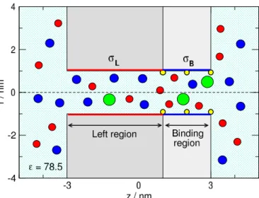
Figure 1.Schematics of the cylindrical pore that is divided into two regions. The left region of lengthHL=4 nm carriesσLsurface charge that determines the main charge carrier of the pore. The right region is the “binding region”, where the binding sites are located (indicated by small yellow spheres on the wall). The length of this region isHB=2 nm and can carryσBsurface charge. The radius of the poreRpore=1 nm in this study. The green sphere is the analyte ion, X+, that is bound to the binding site if it overlaps with the yellow sphere. The blue and red spheres are the cations (K+) and anions (Cl−) of the electrolyte, respectively.
the pore and the membrane are hard, namely, overlap of ions with these walls is forbidden. The pore is divided into two regions along thez-axis (zis the coordinate along the main axis of the pore, perpendicular to the membrane). The left region carryingσLsurface charge has a lengthHL=4 nm.
This is the region whose surface charge determines the main charge–carrier ionic species.
The right region, called binding region, contains the bind- ing sites and carriesσBsurface charge. Its length,HB=2 nm, is half of the left region in this study.
The surface charge is represented by fractional point charges that are situated on a rectangular grid, where a surface element is approximately a square of size 0.2×0.2 nm2. The mag- nitude of the point charges is established so that the surface charge density corresponds to the prescribed values,σLand σB.
We investigated various combinations depending whether the values of surface charges take the value of 1enm−2(de- noted bypand red color in the figures), 0enm−2(denoted by 0and black color in the figures), or -1enm−2(denoted byn and blue color in the figures). The value of theσLcharge is either−1 or 1enm−2, while the value of theσBcharge can take either−1, 0, or 1enm−2. That makes six combinations denoted bynn,n0,np,pp,p0, andpn. In the main text, we will use these notations without colors from now on.
2.2 Interparticle potentials
The electrolyte model is the “primitive” model that represents ions as charged hard spheres of charges,qi, and radii,Ri:
ui j(r) =
∞ for r<Ri+Rj 1
4π ε0ε qiqj
r for r≥Ri+Rj (1) where ε0 is the permittivity of vacuum, ε is the dielectric constant of the electrolyte, andris the distance between two ions. Subscriptican take valuesi= +,−, and X, where these symbols refer to the cation of the electolyte (K+), the anion of the electrolyte (Cl−), and the analyte ion (X+), respectively.
The ionic radii areR+=0.133 nm,R−=0.181 nm (Pauling radii), andRX=0.3 nm, in this study. The concentration of the KCl background electrolyte is fixed at 0.01 M.
The solvent is represented as a continuum background characterized by two response functions. One is the dielec- tric constant, ε=78.5, that describes the screening effect of the water molecules. The other is a diffusion coefficient function,Di(z), that describes the ability of water molecules to affect the diffusion of ions. This function is space de- pendent in our case; it is a piecewise constant function that is different inside the pore (Dporei ) and in the bulk (Dbulki ).
The bulk value is experimental (DK+=1.849×10⁻⁹m2s−1 andDCl− =DX+=2.032×10⁻⁹m2s−1), whileDporei just scales the current without influencing theI/I0ratio. Follow- ing our previous studies [44,15,45,46] here we set the rela- tionDporei =0.1Dbulki . In other studies, where reference was available, we fitted theDporei value to experimental [41,45] or molecular dynamics [43] data.
We placed the binding sites on the pore wall in 3 rings placed atz=1, 2, and 3 nm. Each ring contains 4 binding sites [15]. The binding potential between a site and an analyte ion is the square-well (SW) potential:
uSW(r) =
0 for r−RX>dSW
−εSW for r−RX<dSW, (2) whereris the distance of the site and the ion center. This short-range potential attracts X+with−εSW=−10kTenergy once the closest point of the X+ion’s surface is closer to the site than the distance parameterdSW=0.2 nm. This model takes into account that the active site of the X+ion is usually on its surface while keeping the spherical symmetry of the ion (it neglects the possible orientation dependence of binding).
The SW potential acts only on the X+ions in the simulations.
2.3 NP+LEMC
In the NP+LEMC technique [38] the NP equation is used to compute the ionic flux for ion speciesi
ji(r) =− 1
kTDi(r)ci(r)∇µi(r), (3) whereT=298.15 K is temperature,kis Boltzmann’s constant, ci(r)is the concentration profile,µi(r)is the electrochemical potential profile, andji(r)is the particle flux density.
Solution of the NP equation requires a relation between ci(r)andµi(r). Here we use the Local Equilibrium Monte Carlo (LEMC) simulation method that is an adaptation of the GCMC technique to a non-equilibrium situation. Due to its grand canonical nature, LEMC can handle small concentra- tions easily.
We divide the computation domain of the NP system into volume elements,Dα, and use different µiα values in each volume element. Insertions/deletions of ions are attempted into/from these volume elements with equal probability. These trials are accepted or refused on the basis of the Metropolis algorithm [47]. The acceptance probability contains the local electrochemical potential,µiα, and the energy change. The energy includes every interaction from the whole simulation cell, not only from subvolumeDα. The result of the LEMC simulation in an iteration is the concentration in every volume element,cαi .
The whole system is solved in an iterative way by adjust- ing the electrochemical potential profile (µiα) in each iteration until conservation of mass (∇·ji(r) =0) is satisfied. Transport described by the NP and the continuity equations and statis- tical mechanics handled with LEMC form a self-consistent system. The advantage over the widely used Poisson-Nernst- Planck theory is that the statistical mechanical component is an accurate particle simulation method instead of an ap- proximate mean–field theory (Poisson-Boltzmann) [44,46].
Details are found in earlier papers [38,40].
The computational domain is a closed system (no periodic boundary conditions are applied). We apply boundary con- ditions for concentration (chemical potential) and electrical potential on the boundary of our cell that is a cylinder in this study. Different constant values are applied on the two sides of the membrane at the boundaries of the two half-cylinders as described in our previous studies [38,40]. Since the bound- ary conditions are fixed, the driving force of the transport is maintained, so the transport is steady state.
3. Results
In our previous study [15], we had a negatively charged pore (nn) with the binding sites placed in the middle of the pore, therefore, the pore was symmetric in structure. Consequently, we had only one device functionI/I0, whereIandI0are the currents in the presence and absence of X+ions, respectively.
Here, the pore is asymmetric because of the asymmetric placement of the binding sites in only the right region. This choice reflects the experimental setup where binding sites are placed at the tip of conical nanopores [28,27]. Asymmetric charge patterns can superimpose on this asymmetry. There- fore, rectification as an additional device function appears.
Rectification is defined as|ION|/|IOFF|, whereION andIOFF
are the currents in the open and closed states of the pore, re- spectively. The ON and OFF states are defined by the relation
|ION|>|IOFF|.
We provide a systematic study for various combinations of theσLandσBsurface charges and the effects of these surface
charge patterns on the efficiency of a nanopore-based sensor, where binding sites that selectively bind the analyte ions (X+) are placed in the right (σB) region. The left region is either norp, while the binding region can ben,0, orp. These six combinations denoted bynn,n0,np,pp,p0, andpnhave been studied by performing simulations for varying voltages andX+concentrations.
Figure2shows the current vs. voltage (I−U) curves for all charge patterns and X+concentrations from 0 to 10−3M.
These are the raw data obtained from the simulations and also the primary results produced by experiments. The diverse behavior of theI−U curves as a function of the various charge patterns is apparent. Also, the effect of the varying concentration of the X+ions can be deduced from these plots.
The color code described in subsection2.1is shown by the sketches of the various geometries in Fig.2.
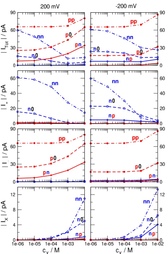
Although the shape of theI−Ucurve can also be con- sidered as a device function, we are interested in a more quantitative analysis. Therefore, we choose two representa- tive voltages (±200 mV) and show detailed results for these cases. Figure3shows the magnitudes of currents as functions ofcX for voltages ±200 mV. Total currents (top row) and currents carried by the individual ionic species (K+, Cl−, and X+from top to bottom) are shown. Figure4shows the device functions plotted against analyte concentration (cX). TheI/I0 ratios are shown for the ON states, because currents are larger in those cases. The voltage -200 mV is the ON state for charge patternsnn,n0, andnp, while 200 mV is the ON state for charge patternspp,p0, andpn. In Fig.4, one of our interest is the sensitivity of the device that we define as the response (eitherI/I0or rectification) given to a given certain degree of input signal (cX). We can also define sensitivity as the slope of the device function vs.cXplot.
Thenncase practically corresponds to the geometry of our previous work [15] except for the fact that the binding sites are placed asymmetrically here (Fig.2A). Accordingly, current decreases with increasingcXas in our previous work (Itot and I+ in Fig. 3). This type of the sensor works on the basis of a competition between the two cationic species, K+and X+. Therefore, while the current of K+decreases with increasing cX, an increase of the X+ current can be observed especially whencXis large enough. The increase of X+current counteracts the decrease of the total (measurable) current (Fig.3), therefore, leaking X+ current makes this setup a less efficient sensor on the basis of theI/I0ratio. Note that the total current shows a better sensitivity tocX in the OFF state (200 mV). As expected, rectification is small, so no additional device function appears in this case (Fig.4B).
The sign of the charge of the X+ion makes the difference between the charge patterns regarding the sign of eitherσL
orσB. As a test, we performed simulations for theppcase (Fig.2B), where the pore is positively charged. Since the X+ ions are repulsed by the surface charges, they do not enter the pore, so they do not influence theI−Ucurves (Fig.2B).
Consequently, this nanopore cannot be used as a sensor (Figs.
Figure 2.Current-voltage curves (Ivs.U) for the different charge patterns. Left panels (A, C, and E) refer to charge patterns, where the left region is negative,σL=−1e/m2, while right panels (B, D, and F) refer to charge pattern, where the left region is positive,σL=1e/m2. Top panels (A and B) refer to uniformly charged pores,nnandpp. Middle panels (C and D) refer to unipolar pores,n0andp0. Bottom panels (E and F) refer to bipolar pores,npandpn. For explanation of notations, see the main text. The values ofσBandσLtake the values -1, 0, or 1 e/nm2. Every panel shows results for different X+concentrations from 0 to 10−3M.
4B and C).
When the surface charges on the right hand side are re- moved (e.g.,σB=0), we obtain unipolar nanopores,n0and p0. These are rectifying pores, but their rectifications are so
small that they do not provide rectification as an additional device function (Fig.4B), at least, for the geometry studied here.. As far as theI/I0ratio is concerned, the n0andp0 geometries behave differently.
Figure 3.Absolute values of currents for two selected voltages (200 mV and -200 mV in left and right panels, respectively) as functions of the X+concentration. The top panels show the total currents, while panels below it from top to bottom show currents carried by the cations, anions, and X+. Thennandppcharge patterns are shown by dot-dashed lines, then0andp0charge patterns by dashed lines, whilenpand pncharge patterns by solid lines. Thenn,n0, andnpcharge patterns are shown in blue with open symbols, while thepp,p0, andpncharge patterns in red with filled symbols. The figure indicates that for then0andnpcharge patterns -200 mV is the ON state, while for thep0and pncharge patterns 200 mV is the ON state.
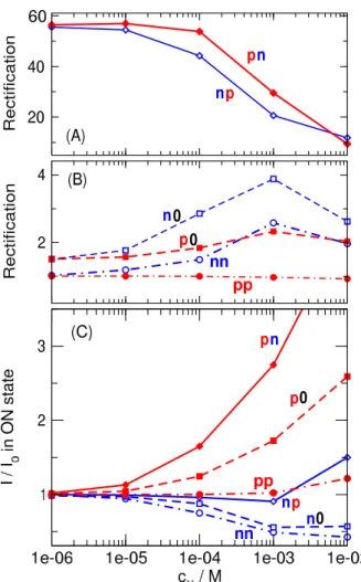
Figure 4.The dependence of the device functions on cXfor the various charge patterns. Panels A and B show the rectification defined as|ION/IOFF|(for then0andnpcharge patterns -200 mV is the ON state, while for thep0andpncharge patterns 200 mV is the ON state). Panel A shows the large rectifications characteristic of the bipolar pores (np andpn). Panel B shows the rectification for the other geometries. Panel C shows the ON-stateI/I0ratio withI0
being the current atcX=0 M.
In then0geometry (Fig.2C), the X+ions are not attracted by theσB =0 surface charge, so they are more reluctant to enter the pore and bind to the binding sites. Therefore, this sensor is less sensitive than thennsensor, especially at small X+concentrations that are our main interest (Fig.4C).
Because rectification is too small to be usable as a device function, this geometry is not an advance compared to thenn geometry.
In thep0geometry (Fig.2D), rectification does not de- pend on the analyte concentration (Fig.4B), but theI/I0ratio increases ascXincreases (Fig.4C). The explanation is that this pore is better in accepting and binding the X+ions compared to thepppore, because the neutralσBregion now does not repel the X+ions. As X+ions bind to the binding sites, they attract more Cl−ions that are the main charge carriers. This geometry has the advantage of excluding the X+ions from the
σLregion and preventing their leakage–current (Fig.3). The increase ofcX, therefore, influences the total current only via influencing the current of Cl−ions. This geometry, therefore, makes a good sensor regarding theI/I0ratio but without the additional benefit from pore asymmetry and rectification (Fig.
4B-C).
As expected, rectification appears as an additional device function when we create bipolar pores: nporpn. Thenp geometry (Fig.2E), as expected, is not a help, because X+ ions are repulsed by the positiveσB charge, so the pore is not sensitive to the presence of X+ions. Although the rec- tification shows a reasonablecXdependence (Fig.4A), the magnitudes of currents are small (much smaller than in thenn case, Fig.2E vs. A) and there is considerable X+leakage (Fig.
3). Small currents are not advantageous for actual devices due to possible problems regarding signal/noise relation.
Thepngeometry (Fig.2F), on the other hand exhibits all the useful behavior that we expect from our device. First, the negativeσBsurface charge attracts the X+ions into theσB region increasing the probability of their presence and binding to the binding sites (Fig.3). This increases the sensitivity of the device to the concentration of X+ions. Second, there is a large rectification that is strongly dependent oncX. Rectifi- cation decreases ascXincreases because the accumulation of the positive X+ions in the right region impairs thepncharge asymmetry of the nanopore (Fig.4A). Third, the total current (and, consequently, theI/I0ratio) has a steady increase as a function ofcXin the ON state (Fig.3and4C).
In the absence of X+, this is mainly anion current, be- cause theσLregion is longer than theσBregion. The ratio of the anion vs. cation currents can be adjusted with the lengths of the two regions,HLandHB. As the concentration of X+ is increased, cation currents decrease because the X+ ions outcompete the K+ions in the right region. In the meantime, the presence of X+ions in the right regions increase the con- centration of the Cl−ions in the right region thus increasing anion current.
All these effects are well visible in Fig.5where the ON- state concentration profiles are plotted for two analyte concen- trations (cX=0 and 10−4M). The top panels show the results for the cases, when the cations are the main charge carriers (σL=−1e/nm2). As discussed above, only thenngeometry behaves as a decent sensor for this case (considered in our pre- vious work [15]). The X+ions accumulate on the right hand side atcX=10−4M while decreasing the K+concentrations there. This results in a decrease of the total current.
The bottom panels show the results for the cases, when the anions are the main charge carriers (σL=1e/nm2). In this case, thepngeometry shows considerable binding of X+ions forcX=10−4M. They squeeze the cations out and attract anions in.
This latter effect is the basis of sensor function. While in thenncase acX-dependent competition between K+and X+ ions was the basis of sensing the X+ions, here an attraction between X+ions and the charge–carrier Cl−ions is the basis
Figure 5.Concentration profiles forcX=0 M (left panels) andcX=10−4M (right panels) for the ON states. Profiles for X+are shown with dashed lines. Solid lines show the profiles for the main charge carriers, while the dot-dashed lines show the profiles for the other ion.
Top panels show the results for thenn,n0, andnpgeometries with solid lines being the cation profiles. Bottom panels show the results for thepp,p0, andpngeometries with solid lines being the anion profiles. The colors are determined by theσBcharge (blue for n, black for 0, and red for p).
of thecX–sensitive effect. This is primarily an electrostatic effect. The X+ions are attracted by the negativeσBsurface charge, but only to the right region. The X+ions tune both the Cl−concentration in the right region and the asymmetry of the pore. This way, both theI/I0ratio and rectification can be used as a device function.
4. Summary
Inspired by experimental works in the field of nanosensing [22,23,24,25,26,27,28], we continued our line of investiga- tion [15] and constructed asymmetric nanopores with various charge patterns. Working with asymmetric nanopores gives rise to an additional device function, rectification, that makes it possible to determine analyte concentration on the basis of two variables instead of just one.
We found that thepngeometry (making a bipolar nanopore) is an appropriate setup for several reasons. The analyte ions are attracted electrostatically (in addition to the square-well short-range attraction), so the pore is sensitive to the pres- ence of the X+ions. The X+ions exert their effect on the main charge carriers (anions) by attracting them. Rectification
is also a proper device function, because the pore becomes less asymmetric as more X+ions are bound. Rectification, therefore, decreases with increasing X+concentration.
In this study we focused on the effect of charge pattern and fixed most of the parameters of our model sensor. In a subsequent study, we present results of extensive simulations for thepngeometry by changing experimentally controllable parameters (pore radius, KCl concentration, charge of ana- lyte ion, and pH) in order to explore the capabilities of this seemingly promising geometry as a sensor.
Acknowledgments
We gratefully acknowledge the financial support of the Na- tional Research, Development and Innovation Office – NKFIH K124353. Present article was published in the frame of the project GINOP-2.3.2-15-2016-00053.
References
[1] L. T. Sexton, L. P. Horne, and C. R. Martin. Developing synthetic conical nanopores for biosensing applications.
Mol. BioSyst., 3(10):667–685, 2007.
[2] R. E. Gyurcs´anyi. Chemically-modified nanopores for sensing.TrAC-Trend. Anal. Chem., 27(7):627–639, 2008.
[3] S. Howorka and Z. Siwy. Nanopore analytics: sensing of single molecules.Chem. Soc. Rev., 38(8):2360–2384, 2009.
[4] A. Piruska, M. Gong, and J. V. Sweedler. Nanofluidics in chemical analysis. Chem. Soc. Rev., 39:1060–1072, 2010.
[5] I. Makra and R. E. Gyurcs´anyi. Electrochemical sensing with nanopores: A mini review. Electrochem. Commun., 43:55–59, 2014.
[6] W. Shi, A. K. Friedman, and L. A. Baker. Nanopore sensing.Anal. Chem., 89(1):157–188, 2016.
[7] M. Lepoitevin, T. Ma, M. Bechelany, J.-M. Janot, and S. Balme. Functionalization of single solid state nanopores to mimic biological ion channels: A review.
Adv. Coll. Interf., 250:195–213, 2017.
[8] D. Stein, M. Kruithof, and C. Dekker. Surface-charge- governed ion transport in nanofluidic channels.Phys. Rev.
Lett., 93(3):035901, 2004.
[9] Z. Siwy, E. Heins, C. C. Harrell, P. Kohli, and C. R.
Martin. Conical-nanotube ion-current rectifiers: the role of surface charge. J. Am. Chem. Soc., 126(35):10850–
10851, 2004.
[10] K. P. Singh and M. Kumar. Effect of surface charge den- sity and electro-osmotic flow on ionic current in a bipolar nanopore fluidic diode. J. Appl. Phys., 110(8):084322, 2011.
[11] S. Nasir, M. Ali, P. Ramirez, V. G´omez, B. Oschmann, F. Muench, M. N. Tahir, R. Zentel, S. Mafe, and W. En- singer. Fabrication of single cylindrical Au-coated nanopores with non-homogeneous fixed charge distri- bution exhibiting high current rectifications. ACS Appl.
Mater. Inter., 6(15):12486–12494, 2014.
[12] H. Zhang, Y. Tian, J. Hou, X. Hou, G. Hou, R. Ou, H. Wang, and L. Jiang. Bioinspired smart gate-location- controllable single nanochannels: Experiment and theo- retical simulation.ACS Nano, 9(12):12264–12273, 2015.
[13] H. Bayley and C. R. Martin. Resistive-pulse sensing from microbes to molecules.Chem. Rev., 100(7):2575–2594, 2000.
[14] Z. Siwy, L. Trofin, P. Kohli, L. A. Baker, C. Trautmann, and C. R. Martin. Protein biosensors based on biofunc- tionalized conical gold nanotubes. J. Am. Chem. Soc., 127(14):5000–5001, 2005.
[15] E. M´adai, M. Valisk´o, A. Dallos, and D. Boda. Simulation of a model nanopore sensor: Ion competition underlines device behavior.J. Chem. Phys., 147(24):244702, 2017.
[16] Z. Siwy, P. Apel, D. Dobrev, R. Neumann, R. Spohr, C. Trautmann, and K. Voss. Ion transport through asym- metric nanopores prepared by ion track etching. Nucl.
Instrum. Meth. B, 208:143–148, 2003.
[17] X. Hou, Y. Liu, H. Dong, F. Yang, L. Li, and L. Jiang. A pH-gating ionic transport nanodevice: Asymmetric chem- ical modification of single nanochannels. Adv. Mater., 22(22):2440–2443, 2010.
[18] J. Cervera, P. Ram´ırez, S. Mafe, and P. Stroeve. Asym- metric nanopore rectification for ion pumping, electrical power generation, and information processing applica- tions. Electrochim. Acta, 56(12):4504–4511, 2011.
[19] H. Zhang, Y. Tian, and L. Jiang. From symmetric to asym- metric design of bio-inspired smart single nanochannels.
Chem. Commun., 49:10048–10063, 2013.
[20] M. Ali, I. Ahmed, S. Nasir, P. Ramirez, C. M. Niemeyer, S. Mafe, and W. Ensinger. Ionic transport through chemi- cally functionalized hydrogen peroxide-sensitive asym- metric nanopores. ACS Appl. Mater. Inter., 7(35):19541–
19545, 2015.
[21] Z. Zhang, L. Wen, and L. Jiang. Bioinspired smart asymmetric nanochannel membranes. Chem. Soc. Rev., 47(2):322–356, 2018.
[22] M. Ali, I. Ahmed, P. Ramirez, S. Nasir, S. Mafe, C. M.
Niemeyer, and W. Ensinger. Lithium ion recognition with nanofluidic diodes through host–guest complexation in confined geometries. Anal. Chem., 90(11):6820–6826, 2018.
[23] M. Ali, I. Ahmed, P. Ramirez, S. Nasir, J. Cervera, S. Mafe, C. M. Niemeyer, and W. Ensinger. Cesium- induced ionic conduction through a single nanofluidic pore modified with calixcrown moieties. Langmuir, 33(36):9170–9177, 2017.
[24] M. Ali, S. Nasir, P. Ramirez, J. Cervera, S. Mafe, and W. Ensinger. Calcium binding and ionic conduction in single conical nanopores with polyacid chains: Model and experiments. ACS Nano, 6(10):9247–9257, 2012.
[25] Q. Liu, K. Xiao, L. Wen, H. Lu, Y. Liu, X-Y. Kong, G. Xie, Z. Zhang, Z. Bo, and L. Jiang. Engineered ionic gates for ion conduction based on sodium and potassium activated nanochannels. J. Am.Chem. Soc., 137(37):11976–11983, 2015.
[26] W. Ensinger, M. Ali, S. Nasir, I. Duznovic, C. Traut- mann, M. E. Toimil-Molares, G. R. Distefano, B. Laube, M. Bernhard, M. Mikosch-Wersching, H. F. Schlaak, and M. El Khoury. The iNAPO project: Biomimetic nanopores for a new generation of lab-on-chip micro sensors.Int. J. Theor. Appl. Nanotech., 6:21–28, 2018.
[27] M. Ali, S. Nasir, and W. Ensinger. Bioconjugation- induced ionic current rectification in aptamer-modified single cylindrical nanopores.Chem. Comm., 51(16):3454–
3457, 2015.
[28] I. Vlassiouk, T. R. Kozel, and Z. S. Siwy. Biosensing with Nanofluidic diodes. J. Am. Chem. Soc., 131(23):8211–
8220, 2009.
[29] K. Wu, K. Xiao, L. Chen, R. Zhou, B. Niu, Y. Zhang, and L. Wen. Biomimetic voltage-gated ultrasensitive potassium-activated nanofluidic based on a solid-state nanochannel.Langmuir, 33(34):8463–8467, 2017.
[30] G. Nie, Y. Sun, F. Zhang, M. Song, D. Tian, L. Jiang, and H. Li. Fluoride responsive single nanochannel: click fab- rication and highly selective sensing in aqueous solution.
Chem. Sci., 6(10):5859–5865, 2015.
[31] Y. Tian, X. Hou, L. Wen, W. Guo, Y. Song, H. Sun, Y. Wang, L. Jiang, and D. Zhu. A biomimetic zinc acti- vated ion channel.Chem. Comm., 46(10):1682, 2010.
[32] M. Ali, M. N. Tahir, Z. Siwy, R. Neumann, W. Tremel, and W. Ensinger. Hydrogen peroxide sensing with horseradish peroxidase-modified polymer single conical nanochannels.Anal. Chem., 83(5):1673–1680, 2011.
[33] G. Hou, H. Zhang, G. Xie, K. Xiao, L. Wen, S. Li, Y. Tian, and L. Jiang. Ultratrace detection of glucose with enzyme- functionalized single nanochannels. J. Mater. Chem. A, 2(45):19131–19135, 2014.
[34] G. P´erez-Mitta, A. S. Peinetti, M. L. Cortez, M. E. Toimil- Molares, C. Trautmann, and O. Azzaroni. Highly sensi- tive biosensing with solid-state nanopores displaying en- zymatically reconfigurable rectification properties.Nano Lett., 18(5):3303–3310, 2018.
[35] Z. Sun, C. Han, L. Wen, D. Tian, H. Li, and L. Jiang. pH gated glucose responsive biomimetic single nanochannels.
Chem. Comm., 48(27):3282, 2012.
[36] J. Hancs´ok, S. Kov´acs, Gy. P¨olczmann, and T. Kasza. In- vestigation the effect of oxygenic compounds on the iso- merization of bioparaffins over Pt/SAPO-11.Top. Catal., 54(16–18):1094–1101, 2011.
[37] C. Berti, S. Furini, D. Gillespie, D. Boda, R. S. Eisenberg, E. Sangiorgi, and C. Fiegna. A 3-D Brownian Dynamics simulator for the study of ion permeation through mem- brane pores.J. Chem. Theor. Comput., 10(8):2911–2926, 2014.
[38] D. Boda and D. Gillespie. Steady state electrodiffusion from the Nernst-Planck equation coupled to Local Equi- librium Monte Carlo simulations.J. Chem. Theor. Com- put., 8(3):824–829, 2012.
[39] Z. Hat´o, D. Boda, and T. Krist´of. Simulation of steady- state diffusion: Driving force ensured by Dual Control Volumes or Local Equilibrium Monte Carlo. J. Chem.
Phys., 137(5):054109, 2012.
[40] D. Boda, R. Kov´acs, D. Gillespie, and T. Krist´of. Selec- tive transport through a model calcium channel studied by Local Equilibrium Monte Carlo simulations coupled to the Nernst-Planck equation.J. Mol. Liq., 189:100–112, 2014.
[41] D. Boda. In R. A. Wheeler, editor, Ann. Rep. Comp.
Chem., volume 10, chapter 5 Monte Carlo Simulation of Electrolyte Solutions in Biology: In and Out of Equilib- rium, pages 127–163. Elsevier, 2014.
[42] Z. Hat´o, D. Boda, D. Gillepie, J. Vrabec, G. Rutkai, and T. Krist´of. Simulation study of a rectifying bipolar ion channel: detailed model versus reduced model. Cond.
Matt. Phys., 19(1):13802, 2016.
[43] Z. Hat´o, M. Valisk´o, T. Krist´of, D. Gillespie, and D. Boda.
Multiscale modeling of a rectifying bipolar nanopore:
explicit-water versus implicit-water simulations. Phys.
Chem. Chem. Phys., 19(27):17816–17826, 2017.
[44] B. Matejczyk, M. Valisk´o, M.-T. Wolfram, J.-F.
Pietschmann, and D. Boda. Multiscale modeling of a rectifying bipolar nanopore: Comparing Poisson-Nernst- Planck to Monte Carlo. J. Chem. Phys., 146(12):124125, 2017.
[45] D. Fertig, M. Valisk´o, and D. Boda. Controlling ionic current through a nanopore by tuning pH: a Local Equi- librium Monte Carlo study.Mol. Phys., in press, 2018.
[46] E. M´adai, B. Matejczyk, A. Dallos, M. Valisk´o, , and D. Boda. Controlling ion transport through nanopores:
modeling transistor behavior. Phys. Chem. Chem. Phys., 20(37):24156–24167, 2018.
[47] N. Metropolis, A. W. Rosenbluth, M. N. Rosenbluth, A. H. Teller, and E. Teller. Equations of state calculations by fast computing machines.J. Chem. Phys., 21(6):1087–
1092, 1953.