Chapter 1. Introduction
Chapter 1
Introduction
1.1 Basic Characterization of Oil-in-Water Emulsion
The food processing industry seeks effective technologies to remove fats, oils and greases from food processing wastewater at acceptable costs. The baking, dairy, oil extraction (e.g., olive, soybean, cotton seed oil), fish processing, meat and poultry industries, as well as manufacturers of oil-containing foods (e.g., margarine and salad dressing) face the problem of reducing the oil contaminant load to downstream wastewater systems. Recovering valuable byproducts, such as proteins and milk fat in the dairy industry, while reducing the biochemical oxygen demand (BOD) and total suspended solids charges from the publicly owned treatment works makes systems that can remove fats, oils and greases increasingly economical [PATTERSON 1985].
Oil and grease is a common pollutant in a wide range of industries. Stable oil-water emulsions are generated in diverse industrial technologies, as shown in Table 1.1.
Industries such as steel, aluminum, food, textile, leather, petrochemical and metal finishing are some that report high levels of oil and grease in their effluents. For instance, in metal working industry oil-water emulsion is often used as coolant and lubricant to increase the useful life of tool and die. In the past time the used emulsion was often discharged to either sanitary sewers or public waterways without previous treatment, causing environmental pollution and loss of oil.
Oil and grease in wastewater can exist in several forms: free, dispersed or emulsified.
The differences are based primarily on size. In an oil-water mixture, free oil is characterized with droplet sizes greater than 150 µm in size, dispersed oil has a size range of 20-150 µm and emulsified oil has droplets typically less than 20 µm. As one of oil-water mixtures, stable oily emulsion is a dispersed system in which the phases are immiscible or partially miscible liquids. The globules of the dispersed liquid are generally between 0.1 µm and 10 µm in diameter, and so are larger than the particles found in sols. If an emulsion is prepared by homogenizing two pure liquid components, phase separation will be rapid, especially if the concentration of the dispersed phase is at all high. To prepare reasonably stable emulsions a third component − an emulsifying agent (or emulsifier) − must be present. The materials which are most effective as emulsifying (and foaming) agents can be broadly
1
Chapter 1. Introduction
classified as: (1) surface-active materials; (2) naturally occurring materials; (3) finely divided solids. The functions of the emulsifying agent are to facilitate emulsification and promote emulsion stability. The emulsifying agent forms an adsorbed film around the dispersed droplets which helps to prevent flocculation and coalescence.
Table 1.1 Oil and grease concentrations in effluents of selected industries [CHERYAN 1998]
Industrial source Oil and grease concentration (mg/l)
Food processing 3 800
Food processing (fish) 13 700
Can production (forming) 200 000
Wool scouring 12 200
Tanning waste, hide curing 40 200
Metal finishing 6 000
Petroleum refinery 3 200
Steel-rolling coolant 48 700
Aluminum rolling 50 000
In nearly all emulsions one of the phases is aqueous and the other is (in the widest sense of the term) oil. If the oil is the dispersed phase, the emulsion is termed an oil-in-water (O/W) emulsion; if the aqueous medium is the dispersed phase, the emulsion is termed a water-in-oil (W/O) emulsion. The type of emulsion which tends to form depends on the balance between the hydrophilic and lipophilic properties of the emulsifier-alkali-metal soaps favour the formation of O/W emulsions because they are more hydrophilic than lipophilic, whereas the reverse holds for heavy-metal soaps.
The amphiphilic nature of many emulsifying agents (particularly non-ionic surfactants) can be expressed in terms of an empirical scale of so-called HLB (hydrophile-lipophile balance) numbers. The latest hydrophilic surfactants are assigned the lowest HLB values. A number of different formulae have been established for calculating HLB numbers from composition data and they can also be determined experimentally, e.g. from cloud-point measurements [SHAW 1991]. For mixed emulsifiers, approximate algebraic additivity holds. Figure 1.1 shows the structure of a stable oil-in-water emulsion.
2
Chapter 1. Introduction
Water Oil
Figure 1.1 Schematic diagram of stable oil-in-water emulsion
The application of oil-in-water emulsion is numerous. Among the industries where oil-in-water emulsion is encountered are petroleum, cosmetic, pharmaceutical, agriculture, food, polymer, textile, paper, prints, polish and leather [MARK 1990, HAGG 1998, NABI and MEIRELES 2000]. The used emulsion was often discharged to either sanitary sewers or public waterways without treatment in the past time. It resulted in environmental pollution and loss of oil [LAHIERE and GOODBOY 1993, NAZZAL and WIESNER 1996, BENNETT 1973, 1983, HILL 1983]. Therefore, it is of great significance to study the separation behavior of oil-in-water emulsion to environmental protection.
1.2 Separation Methods for Oil-in-Water Emulsion
1.2.1 Conventional treatment methods
Conventional approaches to treating oily wastewaters have included gravity and skimming, dissolved air flotation, de-emulsification, coagulation and flocculation [NOEMAN 1982]. Gravity separation followed by skimming is effective in removing free oil from wastewater. Oil-water separators such as the API separator and its variations have found widespread acceptance as an effective, low cost, primary treatment step. These, however, are not effective in removing smaller oil droplets and emulsions. Oil that adheres to the surface of solid particles can be effectively removed by sedimentation in a primary clarifier.
Dissolved air flotation (DAF) uses air to increase the buoyancy of smaller oil droplets and enhance separation. Emulsified oil in the DAF influent is removed by de-emulsification with chemicals, thermal energy or both, DAF units typically employ chemicals to promote coagulation and increase floc size to facilitate separation.
3
Chapter 1. Introduction
Emulsified oil in wastewater is usually pretreated chemically to destabilize the emulsion followed by gravity separation [DICK 1982]. The wastewater is heated to reduce viscosity, accentuate density differences and weaken the interfacial films stabilizing the oil phase. This is followed by acidification and addition of cationic polymer/alum to neutralize negative charge on oil droplets, followed by raising the pH to the alkaline region to induce floc formation of the inorganic salt. The resulting floc with the adsorbed oil is then separated, followed by sludge thickening and sludge dewatering. In some cases, the sludge may be further processed. Frequently, a high molecular weight flocculant such as acrylate-acrylamide copolymers may be used to enhance oil removal and reduce floc carry over. Improvements in chemical treatment are frequently centered on selection of the appropriate blend of chemicals, and process optimization to lower costs of operation.
Physical methods for breaking emulsions include heating, centrifugation, precoat filtration, fiber beds, ultrafiltration and reverse osmosis, and electrochemical methods.
Centrifugation is normally applied to oily sludges though it might be employed for small volumes of dilute oil waste in special cases. Precoat filtration and coalescers have also been successfully employed for breaking oil emulsions. Typically, precoat filtration and coalescers are used for separating particles in the 20 − 100 µm size range. Electrocoagulation and electroflotation are some of the other technologies that utilize both chemical and physical emulsion separation mechanisms in the presence of an electric field.
Gravity separation is the most common primary treatment of oily wastewater. If the resulting effluent does not meet required discharged limits, secondary treatment steps are used to lower the levels of dissolved, emulsified and dispersed oils. Breaking of emulsions with chemicals, followed by DAF or sedimentation, is then used to remove additional oil.
Chemical emulsion breaking is effective if properly applied, but it suffers from several shortcomings [CHERYAN and RAJAGOPALAN 1998]:
1. The process is highly susceptible to changes in influent quality.
2. It requires customization at every site to determine the type and quantity of chemicals required.
3. It requires close control and skilled operators to achieve optimal operation.
4. It produces large volumes of sludge.
5. The equipment has a large footprint.
4
Chapter 1. Introduction
6. The operating costs can be high, depending on the application.
7. There could be corrosion problems due to acidification of the influent.
8. Mechanical problems may arise due to clogging of chemical feeding lines.
9. Dissolved solids content in the effluent increases.
10. It is more suitable for large volumes, e. g. > 1.0 × 10⁶ liters per day; it is difficult to operate and maintain in smaller facilities with fewer resources.
Thermal treatment (evaporation and incineration) is more universal and perhaps more suitable for many types of oily emulsions. Its drawbacks are high-energy costs and loss of entrained oils in the vapors from the evaporators, making it necessary to treat the condensate.
Coalescers and precoat filtration are more effective in reducing high levels of oil and grease in the appropriate particle size range. Problems can be encountered in coalescers due to gradual adsorption of material on the coalescing media. This leads to its poisoning and loss of effectiveness. The extra volume of sludge produced is a problem with precoat filtration and electrocoagulation.
1.2.2 Membrane technology
Membrane processes such as microfiltration (MF), ultrafiltration (UF), nanofiltration (NF) and reverse osmosis (RO) are increasingly being applied for treating oily wastewater [BHAVE and FLEMING 1988, CHEN et al. 1991, DAIMINGER et al.
1995]. Of the three broad categories of oily wastes −− free-floating oil, unstable oil/water emulsions, and highly stable oil/water emulsion -- membranes are most useful with stable emulsions, particularly water-soluble oily wastes. Free oil, on the other hand, can be readily removed by mechanical separation devices which use gravitational force as the driving force. Unstable oil/water emulsion can be mechanically or chemically broken and then separated by gravity. Pretreatment to remove large particles and free oil is needed, especially if thin-channel membrane equipment is used. The membrane unit is usually operated in a semibatch recycle. The wastewater feed is added to the process tank at the same rate as clean permeate is withdrawn, thus keeping a constant level in the tank. The retentate containing the oil and grease is recycled to the process tank. When the oils and grease and other suspended matter reach a certain predetermined concentration in the tank, the feed is stopped and the retentate allowed to concentrate. Usually, this results in a final concentrate volume that is only 3-5% of the initial volume of oily wastewater fed to the process tank. The system is then usually cleaned.
5
Chapter 1. Introduction
Membranes have several advantages, among them:
1. The technology is more widely applicable across a wide range of industries.
2. The membrane is a positive barrier to rejected components. Thus, the quality of the treated water (the permeate) is more uniform regardless of influent variations.
These variations may decrease flux, but generally does not affect quality of its output.
3. No extraneous chemicals are needed, making subsequent oil recovery easier.
4. Membranes can be used in-process to allow recycling of selected waste streams within a plant.
5. Concentrates up to 40-70% oil and solids can be obtained by UF or MF. Since most oily wastes contain 0.1-1% oil, this means the volume of waste that has to be subsequently hauled away or treated is reduced to 1/40-1/200 the initial feed volume.
6. Membrane equipment has a smaller foot print.
7. Energy costs are lower compared to thermal treatments.
8. The plant can be highly automated and does not require highly skilled operators.
For example, flux that can be obtained with Koch’s tubular modules is about 50 l/m2h at 25 oC and 3.5 bar, with emulsified oil at 1-2% feed concentration and 60% retentate concentration [CHERYAN and RAJAGOPALAN 1998]. Synthetic oils tend to foul the membrane less and have high flux. Natural fats and oils exhibit low flux and foul the membrane more. The chemical nature of the membrane can have a major effect on the flux. For instance, free oils can coat hydrophobic membranes resulting in poor flux (emulsified oil is usually not as much of a problem, unless it is concentrated to such a high level that the emulsion breaks, releasing free oils). Hydrophilic membranes preferentially attract water rather than the oil, resulting in much higher water flux. Hydrophobic membrane can be used, but usually in a tubular configuration that allows a high degree of turbulence (cross-flow velocity) to be maintained to minimize oil wetting of the membrane.
Membranes with pore sizes equivalent to 50 000-200 000 molecular weight cut off (MWCO) should result in permeates with less than 10-100 ppm of oil, unless high concentrations of a soluble surfactant or polar solvent are present. MF membranes with pore sizes of 0.1 µm have also been used, especially if it is necessary to recover surfactants in the permeate. If the salt content of the oily wastewater is too high for direct reuse of the permeate in the plant, it can be treated by RO or NF.
Membrane processes have some limitations:
6
Chapter 1. Introduction
1. Scale-up is almost linear above a certain size. Thus capital costs for very large effluent volumes can be high.
2. Polymeric membranes suffer from fouling and degradation during use. Thus they may have to be replaced frequently (generally every two years[CHERYAN and RAJAGOPALAN 1998], which can increase operating costs significantly).
In spite of the above disadvantages, membrane processing of oily wastewaters, sometimes in conjunction with other methods for treating the residuals, is a commercial success with more than 3 000 polymeric UF/MF installations and over 75 inorganic/ceramic units worldwide. Membranes are gaining wider acceptance for two reasons: it consistently produces effluents of acceptable discharge quality and it is perceived to be a simple process from an operational viewpoint.
1.3 Objectives of This Thesis
Industrial wastewater treatment, pollution prevention, and resource recovery applications frequently require separation of emulsified oils. Membrane filtration technologies are playing a more prominent role in accomplishing these separations.
Ultrafiltration is an effective and economical method to treat emulsified oily wastewater from the industry. Ultrafiltration is also a physical treatment process to remove contaminants from an oily wastewater and permit sewer discharge, and can be used to comply with strict environmental laws as well as provide a first step towards water recycling and oil recovery.
The basis for selecting membranes and membrane operating conditions for removing water from oily water supplies and wastewater streams remains largely empirical, which includes molecular weight cut off (MWCO), pore size and distribution, transmembrane pressure, temperature, flow velocity, cleaning of membrane and others to achieve adequate rejection of emulsified oil and chemical oxygen demand (COD) in the permeated water while maintaining permeate flux.
Therefore, the objectives of this investigation are the establishment of operation conditions and selection of membrane parameters to minimize concentration polarization and membrane fouling, the achievement of adequate rejections of COD and oil, and the development of a suitable pilot scale-up procedure involving membrane module arrangements, operation parameters and membrane nature to obtain the high water recovery essential in oil-in-water emulsion treatment.
7
Chapter 1. Introduction
The concentration polarization and membrane fouling is a serious problem in membrane filtration. It is well known that many models for cross-flow membrane filtration have been reported in the literatures. These models, especially film theory and the resistance-in-series model, have been modified for ultrafiltration of oil-in-water emulsion by many authors, as stated in the following section of literature survey. However, there is no generally accepted, simple and practical comprehensive model. The reasons may be ascribed to the membrane variety and composition complexity of oil-in-water emulsion etc. In actual ultrafiltration process, the theoretical results were not in good agreement with the experimental values.
The second goal of this research is to introduce a calculation method of gel concentration at the membrane surface and to develop a new numerical model which can describe the flux decline behavior due to membrane fouling during cross-flow UF of oil-in-water emulsions. The theoretical analysis and calculation have to be verified by many experimental results.
1.4 Outline
A review of the literature available will be presented in Chapter 2. Current technology and novel developments of ultrafiltration characteristics and membrane technology, especially in the application of separation of oil-in-water emulsion, will be explained more extensively in this chapter.
Chapter 3 will be devoted to the description of experimental procedures, including experimental apparatus, membranes and methods either in laboratory or pilot field.
In Chapter 4 the influence of membrane type and operation condition on the flux were investigated in laboratory and pilot scales. The recovery of permeability of ultrafiltration membrane was subsequently studied. Then the next section is dedicated to the characterization of gel concentration at the membrane surface.
In the last section of Chapter 4 the theoretical results of the membrane fouling model will be compared with experimental results under various operation conditions.
Conclusions and research potentials will be given in Chapter 5.
8
Chapter 2. Literature Survey
Chapter 2
Literature Survey
The ultrafiltration membrane process is quite recent and presents undeniable advantages: it needs no chemical reagent, the ultrafiltered water shows no oil content, the ultrafiltration plants are quite compact and are fully automated [LOEB and SOURIRAJAN 1964]. Therefore the research and development on the ultrafiltration behavior of oil-in-water emulsion have been investigated worldwide. Many studies have reported the application of ultrafiltration to the treatment of oil-in-water emulsions [ANDERSON and SAW 1987, DAL-CIN et al. 1998, VIADERO et al.
2000, LIN and LAN 1998].
However, two kinds of limitations are commonly encountered in this process: (1) Concentration polarization due to the accumulation of oil droplets on the membrane surface. This over-concentration leads to the formation of a viscous oily gel layer containing 30 to 40% of oil and which causes a strong decrease in the flux [LEE et al.
1984]; (2) Membrane fouling due to an inlet of oil drops into some pores or to the adsorption of either oil or surfactants or co-surfactants or of some other organic matter on the membrane surface. This long term phenomenon causes a progressive decrease of the flux over time and can induce a loss of separation efficiency in the fouled areas.
Therefore, the major hurdles to be overcome in the development of a practical industry unit are concentration polarization and membrane fouling. Almost the current researches of ultrafiltration in oil-in-water emulsion have been focused on the problems mentioned above, in order to improve the permeate flux. They contain: (1) the mechanisms of concentration polarization and membrane fouling [LEE et al. 1984, VAN DEN BERG and SMOLDERS 1989, NAKAO et al. 1986, FERNANDEZ-SEMPERE and RUIZ-BEVIA 1996, GEKAS and HALLSTROM 1987]. (2) preventing or reducing methods of concentration polarization and membrane fouling [AGASHICHEV 1999, KARODE 2000, HAMZA et al. 1997, LIPP 1988, MA et al. 2000]. (3) membrane material (including novel membrane material and its surface modification etc) [HYUN and KIN 1997, GANCARZ 2000, HOWELL et al. 1994, CASTRO et al. 1996, PEINEMANN and NUNES 1994, LINDAU and JONSSON 1999]. (4) optimizing the basic operation parameters (transmembrane pressure, cross-flow velocity, feed concentration, temperature) [CROZES et al. 1997, LOPEZ et al. 1995, LINDAU 1998, MORES and DAVIS
9
Chapter 2. Literature Survey
2000]. (5) pretreatment of chemical adjunction salt in the feed solution [TECKENTRUP 1995] and additional force fields (using an external DC electric field) [CORNELISSEN 1997, HUOTARI et al. 1999] or ultrasonic treatment [CHAI et al. 1998, 1999]. (6) membrane cleaning procedure and novel hybrid process combining with biotechnology, gravity, air-flotation and other treatment methods [TROUVE 1994, CANNING and TONELLI 1995, LINDAU and JONSSON 1992].
2.1 Mechanism of Concentration Polarization and Membrane Fouling
Ultrafiltration (UF) has a great potential for removing particles, microorganisms, and colloidal material from potable water supplies and wastewater streams. A major obstacle to these applications is that the permeate flux decline due to concentration polarization and fouling. During ultrafiltration of colloidal suspensions, particles within the feed and recycled flow stream are convectively driven to the membrane surface where they accumulate and tend to form a cake or gel layer. This particle build-up near the membrane surface is known as concentration polarization, and results in increasing hydraulic resistance to permeate flow; therefore the permeate flux declines in function of time.
It is believed that there are two essential mechanisms for membrane fouling in cross-flow UF, namely, pore blocking which is responsible for the initial sharp drop from the flux of pure water filtration, and cake formation which is the reason of long-term gradual flux decline [SONG 1998]. Both pore blocking and cake formation may be affected by many factors. The necessary condition for pore blocking and cake formation (or the fundamental cause of membrane fouling) is the non-equilibrium operation of UF, where the applied pressure is much higher than the critical pressure that can be absorbed by the concentration polarization layer. In such operation, the membrane pores will be quickly blocked and a cake layer will form to absorb the excessive pressure.
It was investigated that the transition from concentration polarization to cake formation for the membrane filtration of colloidal silica by imposing flux and observing the system response [CHEN et al. 1997]. It appears that once Jcrit is exceeded, the colloids in the polarized layer form a consolidated cake structure that is slow to depolarize and which reduces the flux. These results are ascribed to formation of a stagnant, highly concentrated layer near the membrane surface due to consolidation and aggregation of solute resulting from very rapid flux increases.
10
Chapter 2. Literature Survey
NIKOLOVA et al. [1998] explained the mechanism of flux decline: in absence of flow through the membrane, some macromolecules are adsorbed on the membrane surface. Thus the initial total resistance is higher than that the membrane exerts during the filtration of pure water. The higher the feed concentration, the higher the initial adsorbed layer resistance. During the ultrafiltration process, gradually a concentration polarization layer is developed, causing increased osmotic pressure and increased adsorption resistance. The later plays the decisive role in the flux decline.
Some results on the fouling mechanism have been reported for UF membranes used for the removal of lubricating and cutting oils used in the metal industry.
BHATTACHARYYA et al. [1979] observed internal and external fouling during UF of a lubricating oil-nonionic detergent-water solution through noncellulosic, tubular membranes. They noted that membrane fouling and cleaning requirements depend on the type of oily water systems and membranes. LEE et al. [1984] studied concentration polarization and fouling during UF of a soluble oil-surfactant-water emulsion through a polymeric membrane in a stirred filtration cell. They found that fouling was due to adsorption of oil on the membrane structure, which modified the critical surface tension and the wettability, as well as the effective pore diameter, resulting in reduced membrane permeability. LIPP et al. [1988] studied the UF behaviour of soluble oil-in-water emulsions through a batch cell containing various polymeric and cellulosic membranes. They stated that fouling followed a gel-polarized, film-model behavior, with the oil droplets coalescing into the surface-fouling oil film. In addition, MUELLER et al. [1997] reported that the UF performance of cutting oil with polysulfone membranes was studied. It is presented that the results of changing various operating variables, including the increase in flux observed at higher cross-flow velocities due to washing away of the polarized layer.
They also proposed a model for the prediction of the permeate flux which incorporates droplet coalescence and shear rate.
POPE et al. [1996] reported measurements of the thickness of the concentration polarization layers formed during cross-flow membrane filtration of an oil-water emulsion. The formation and development of the oil polarization layers was visualized non-invasively using NMR (nuclear magnetic resonance) chemical shift selective micro-imaging. A series of images was acquired during the transient state of the filtration, (i.e. while the polarization layer was forming and the flux of filtrate was changing), prior to the establishment of steady state conditions. An estimate of the specific resistance of the concentration polarization layers was then obtained by determining the average oil layer thickness and concentration at a given time from the resulting images and measuring the corresponding (length averaged) flux of filtrate
11
Chapter 2. Literature Survey
gravimetrically. After the establishment of steady state conditions, the dependence of the steady state filtrate flux on cross-flow Reynolds number was found to be consistent with Brownian diffusion being the main mechanism controlling the build-up of the oil polarization layers, at least under a special range of operating conditions.
2.2 Mathematical Models of Permeate Flux
The capital and operational costs of membrane systems are directly dependent on membrane permeate flux. Therefore, the permeate flux and the factors affecting it are central considerations in determining membrane process performance and cost.
Many different models have been proposed to predict flux decline during UF and MF [LEE et al. 1984, VAN DEN BERG and SMOLDERS 1989, CHEN et al. 1997, KOLTUNIEWICZ et al. 1995, ARNOT et al. 2000, CAKL et al. 2000]. Among them there are two basic models: one is the gel layer model [TANSEL et al. 2000, LEE and CLARK 1998, BLATT et al. 1970] in which the extra hydraulic resistance of a gel layer in addition to the membrane resistance reduces the flux, and the other is the osmotic pressure model [FANE 1986, SOURIRAJAN and MATSUURA 1988] in which the applied pressure is reduced by the osmotic pressure and the decreased driving force causes the flux decline. When a suspension or emulsion contains molecules which are too large to enter the membrane pores, then a sieving mechanism is dominant and a cake layer of rejected molecules forms on the membrane surface.
The cake layer provides an additional resistance to filtration, so the permeate flux declines in function of time. The cake layer and membrane may be considered as two kinds of resistance in series, and the permeate flux is then described by Darcy’s law provided neglecting the effect of diffusion:
) (Rm Rc J P
+
= ∆
η (1.1) where J = permeate flux, ∆P = transmembrane pressure, η = viscosity of the permeate, Rm = membrane resistance, and Rc = cake resistance. The cake filtration theory has been successful in describing flux decline during dead-end MF/UF of particulate suspensions. Many experimental results demonstrate the well-known relationship drawn from cake filtration theory, V ∝ t1/2 (V = total volume of permeate, t = filtration time). The theory for the transient cake build-up and the associated flux decline for conventional dead-end filtration may also apply for the initial cake build-up in cross-flow filtration, prior to the action of the tangential flow which
12
Chapter 2. Literature Survey
causes the cake growth to be restrained [DAVIS 1992]. Macromolecules and/or colloidal molecules experience diffusion is not considered in this model.
The concentration polarization model based on the film theory was developed to describe the back diffusion phenomenon during filtration of macromolecules. In this model, the rejection of molecules gives rise to a thin fouling layer on the membrane surface, overlaid by a concentration polarization layer in which molecules diffuse away from the membrane surface. At steady state, convection of molecules towards the membrane surface is balanced by diffusion away from the membrane [PORTER 1972]. If the solute retention is assumed to be equal to one, i. e. all molecules are assumed to be rejected by the membrane, then the steady-state permeate flux can be obtained by integrating the one-dimensional convective-diffusion equation across the concentration polarization layer:
b w b
w
C K C C C
J = Dln = ln
δ (1.2) where D = diffusion coefficient, δ = thickness of concentration boundary layer, Cw = rejected molecules volume fraction at the wall, Cb = rejected molecules volume fraction in the bulk solution, and K = mass transfer coefficient = D/δ. This model introduces two important parameters – the mass transfer coefficient (K) and the rejected molecules volume fraction at the wall (Cw) – which should be determined either theoretically or experimentally.
Two distinctive models have been developed: one is the lateral migration model and the other is the shear-induced hydrodynamic diffusion model. According to the lateral migration model proposed by GREE and BELFORT [1980], the permeate flux declines until the permeation velocity equals the lift velocity evaluated at the surface of cake layer. However, during membrane filtration the diffusion is another important mass transport mechanism, and this was not considered in GREEN and BELFORT’s model. It was proposed to modify the concentration polarization model by replacing the Brownian diffusion coefficient with the shear–induced hydrodynamic diffusion coefficient [ZYDNEY and COLTON 1985]. In addition, it was developed a more comprehensive model based on the shear–induced hydrodynamic diffusion phenomenon [DAVIS and LEIGHTON 1987, ROMERO and DAVIS 1988]. They deliberately incorporated two-dimensional characteristics of cross-flow filtration into the one-dimensional convective-diffusion equation by defining the shear-induced hydrodynamic diffusion coefficient.
13
Chapter 2. Literature Survey
As an alternative to back-transport of molecules away from the membrane by mechanisms such as shear-induced diffusion and inertial lift, it is possible that the molecules are carried to the membrane surface by permeate flow and then roll or slide along the membrane surface due to the tangential flow. The rejected molecules are assumed to form a flowing cake layer. Convective-flow mathematical models describe the simultaneous deposition of molecules into the cake layer and the flow of this layer towards the filter exit [LEONARD and VASSILIEFF 1984, DAVIS and BIRDSELL 1987]. The fully developed laminar flow equations were solved for the velocity profiles in the bulk suspension and in the cake layer, and the thickness and the permeate flux at a steady state cake can be determined. In general, the cake layer thickness increases and the permeate flux decreases with increasing distance from the filter entrance. This surface transport model predicts that the steady state permeate flux increases with shear rate and radius of rejected molecules.
Recently, many attempts have been made to fully describe two-dimensional mass transport mechanisms involved in cross-flow filtration [LEE and CLARK 1998]. The most popular one is the continuum approach. The particle movement during cross-flow filtration is governed by the two-dimensional convective-diffusion equation. Many different authors have tried to solve the differential equation numerically in order to obtain the concentration profiles inside the membrane channel;
most of these efforts were limited to the steady-state case. Although the concentration profiles can explain the trends in flux decline, they can not be directly used to predict the flux decline. Therefore, it is necessary to develop a comprehensive model which can predict the flux decline during cross-flow filtration.
2.3 Flux Enhancement Methods
Flux decline in membrane filtration is a result of the increase of the membrane resistance because of the development of those additional resistances, such as concentration polarization and fouling resistances. The successful operation of membrane plant requires careful management of polarization and fouling of the membrane. Their avoidances are probably not possible, but their impacts can be limited by a variety of techniques. The choice of membrane, module, process configuration and pretreatment are all important to varying extents, if a high degree of separation is to be achieved without productivity being lessened unacceptably by fouling and polarization. In addition to improve filtration rates, avoidance of fouling makes easier to clean the membranes. This may limit the need for a severe cleaning regime and can prolong the service lifetime of polymeric membranes.
14
Chapter 2. Literature Survey
2.3.1 Pretreatment
Permeate flux can be enhanced by pretreating the feed. This technique is commonly used either to remove particles that may cause clogging in the module or to prevent particles or macromolecules from reaching and depositing on the membrane surface, or to reduce the total contaminant load in downstream membrane modules. The use of innovative pretreatment can significantly extend the UF volumes that can be economically treated.
Pretreatment can involve either physical or chemical processes. Physical processes usually include prefiltration or centrifugation to remove suspended solids which may plug the module or blind the membrane. Chemical processes include feed pH adjustment so that molecular or colloidal foulants will be far from their isoelectric point, thereby reduce the tendency to form a gel layer. It may involve precipitation, coagulation or flocculation or the use of proprietary chemicals such as anti-scalants or disinfectants.
BELKACEM et al. [1995] reported their dedication on the application of membrane technology for wastewater treatment of metal working fluids and more precisely of oily emulsion stabilized by anionic surfactants. The permeate fluxes have been considerably increased by the adjunction of a reactive salt (CaCl2) at a very low concentration in the feed solution. After this treatment, the ultrafiltration membrane behaves as efficient surface coalescer. This treatment and procedure reduces the polarization layer resistance giving an increased permeate flux which is nearly constant and independent of the concentration ratio.
WEHLE et al. [1988] used a method to break emulsion in pretreatment of feed. They invented an apparatus for treating an oil/water emulsion having a reaction vessel and an emulsion-breaker vessel, from which emulsion breaker can be delivered into the reaction vessel. A sensor device being provided for the determination of transmitted light and scattered light as a measure of turbidity of the oil-in-water emulsion in the reaction vessel. The addition of emulsion breaker can be controlled according to measurement results obtained by the sensor apparatus. Furthermore, the invention also relates to a process for treating an oil/water emulsion, in which the water emulsion is first divided, with addition of an emulsion breaker and vortexing, into flocks which can be separated off on the one hand residual dispersion, on the other hand the flocks are separated off from the residual dispersion, contaminated residual water arising in the process being subjected to a membrane filtration.
15
Chapter 2. Literature Survey
2.3.2 Operation conditions
Optimizing the operation conditions may involve maintaining a high cross-flow velocity, limiting transmembrane pressure, temperature, periodical hydraulic and/or mechanical cleaning, choice of cleaning chemicals and frequency of cleaning etc.
Concentration polarization and cake formation in commercial membrane module is controlled either by increased shear at the membrane surface or the use of turbulence inducers. Increased shear is obtained by pumping the feed at higher flow-rates or by using thin flow channels above the membrane surface. The performance of membrane processes can be improved when unsteady fluid instabilities are superimposed on cross-flow. Whereas steady flows often require high cross-flow velocities in the turbulent regime, unsteady flows can be effective in both the laminar and the turbulent regimes. These fluid instabilities have been used to disturb foulants, and rough channels have been used to induce fluid mixing at the membrane-solution interface [CHUNG et al. 1993].
The high feed/retentate velocities used in UF modules require a high pressure, but a low transmembrane pressure is needed to prevent compaction of deposits on the membrane. In addition, high pressure may cause other problem in UF of oil-in-water emulsion, because there are some surfactants in emulsion. Sweet reported that the surfactants present in water/oil/surfactant emulsions can be selectively separated from the emulsions by practicing an ultrafiltration process under specific conditions of pressure and ultrafiltration membrane pore size [SWEET 1990]. It has been discovered that increasing the applied pressure results in an increase in the permeability of the surfactant without a commensurate increase in the permeability of the water or oil.
MISRA et al. [1999] studied model metalworking fluids, characterized by phase separation of functional components at elevated temperatures. Results of membrane filtration experiments with three oils of different chemical nature confirm the feasibility of specific removal of finely dispersed contaminant oils without the simultaneous loss of active components from adequately formulated fluids.
Prerequisites are that membrane materials and pore sizes be suitably chosen and that operating temperatures be kept below the cloud point of the least soluble component.
The most suitable filter was a hydrophilic regenerated cellulose membrane with a MWCO of 100 000 Dalton. It was also found that intrinsically water-soluble boundary lubricants of the polyglycol ether type are retained by membranes. This is of considerable practical importance since it offers the possibility of designing
16
Chapter 2. Literature Survey
water-soluble boundary lubrication and extreme pressure additives which are activated by the presence of an inversely soluble component above its cloud point.
LOPEZ et al. [1995] emphasized the importance of the temperature in cross-flow UF of hydrocarbon emulsions. The flux performance depends on the droplet size distribution which depends strongly on the temperature. The flux has a maximum at 25oC but the internal clogging limits the membrane regeneration by counter-washing.
At 18oC, the fouling results essentially from the accumulation of oil against the wall of the membrane.
The high feed/retentate velocities reduce cake formation and polarization in ultrafiltration. The pressure drop on the feed side is therefore fairly high, while the permeate channel is often at, or near to, atmospheric pressure. The transmembrane pressure at the feed end of the filter is therefore greater than at the retentate discharge end, causing more cake formation (the extent of compaction depends on the properties of the feed) at the feed end. This leads to a rapid drop in flux and high rejection of solutes. It is common practice to pump filtrate back through the membrane into the feed channel to give a periodic backwash to lift deposited material off the membrane surface. SRIJAROONRAT et al. [1999] studied the backflushing effect in UF treatment of unstable secondary oil/water emulsion. It was found that the ceramic membrane (α-alumina or zirconium) could be used successfully to treat oily wastewater. The concentration polarization and fouling can be controlled by periodic backflushing with ceramic membrane, and the flux was found to increase. Rapid backwashing (also known as back-pulsing or back-shocking) is sometimes more effective. Back-pulses are of short duration (about 0.1 second or shorter) and can be particularly useful with colloidal suspensions and with streams requiring protein transmissions through the membrane [CHERYAN 1998].
Besides the periodic hydraulic cleaning and mechanical cleaning, chemical cleaning is also used to enhance flux and reduce fouling. Cleaning solutions are usually circulated with a pressure somewhat lower than that used during filtration to prevent deeper penetration of the foulants into the membrane. There is no a priori rule which can be applied to predict which cleaning technique might be most successful in any particular application. KIM et al. [1993] investigated the relationships between membrane fouling and cleaning in terms of flow conditions, transmembrane pressure, pH, membrane properties and cleaning agents using a stirred batch-cell and aqueous albumin solution. In addition, BELKACEM et al. [1995] introduced also the application of specific micellar cleaning solutions to fouled membranes to renew their initial water permeability and their initial hydrophilic properties.
17
Chapter 2. Literature Survey
2.3.3 Process design
The process design may include additional force fields (for example electric and/or ultrasonic), choice of membrane material and modification of membrane surface, use of turbulence promoters, pulsed/reversed flow and rotating/vibrating membranes etc.
The application of an electric field to improve the efficiency of pressure driven filtration processes has been practiced for a long time. [HUOTARI et al. 1999a, 1999b] reported the effect of an electric field in the filtration of an oil emulsion.
Limiting fluxes for low flow rate increased significantly under the conditions studied, from 75 l/m2h without an electric field to more than 350 l/m2h using an electric field.
The limiting flux increase was affected by the electrophoretic mobility of the oil droplets and the applied electric field strength. The critical electric field strength was determined, and experimentally obtained values were corresponded with calculated values. Permeate quality was also improved to some extent and a membrane with a large pore size could be used when using the electric field.
The passage of ultrasound waves through a suspension can cause many phenomena, including particle dispersion, viscosity reduction, changes in particle surface properties and cavitation [KOST and LANGER 1988]. CHAI et al. [1998] reported that an ultrasound cleaning technique was applied to remove fouling of ultrafiltration and microfiltration membranes, as peptone solution was permeated by cross-flow filtration. The ultrasound employed had a frequency of 45 kHz and an output power of 2.73 W cm-2. For each polymeric membrane made of polysulfone, polyacrylonitrile and polyvinylidene fluoride, cleaning experiments were carried out with three kinds of methods using sonication, water cleaning and water cleaning under sonication. It was found that water cleaning under sonication was an effective method for the recovery of permeate flux. The ultrasound effect on the cleaning of fouled membranes was also examined at different filtration temperatures using various peptone concentrations. It is suggested that the cleaning of fouled membranes by ultrasound association with water cleaning is an effective new method.
The membrane material influences the separation behaviour to a greater degree in case of ultrafiltration, largely through the tendency of some materials to adsorb solutes more readily than others do. Appropriate choice of membrane material and modification of membrane surface can lead to looser binding of the solutes to the membrane surfaces, which can have the effect of lessening and membrane-solute interaction (such as molecule or particle penetration into the surface pores). This leads to a reduction in membrane permeability, and it may also make the solute easier to
18
Chapter 2. Literature Survey
remove during cleaning. In addition, modification of membrane surfaces to increase hydrophilicity is also selectable in UF of oil-in-water emulsion. HAMZA et al. [1997]
has developed a membrane with low surface energy to reduce fouling in UF-applications, and reports successful results from experiments with a surface modified polyethersulfone (PES) ultrafiltration membrane. The surface was modified with various amounts of macromolecules as additives, and it was found that a modified PES-membrane had higher flux when treating oil-in-water emulsion, than the control membrane (unmodified).
It is also noticed the difference in permeate flux by Nakatsuka and Miyano where a hydrophilic cellulose acetate (CA) membrane was compared with a hydrophobic PES membrane [NAKATSUKA et al. 1996]. The flux through the CA membrane was found to be much higher than that of the PES-membrane, a phenomenon which was explained by the difference in membrane fouling due to adsorption of substances in raw water on and in the pores of the membranes. In order to maintain the high and stable flux on the CA-membrane the operating back-washing pressure would be more than twice higher than the filtration pressure. Efficient removal of organic compounds from raw water was accomplished by the CA-membranes.
It was invented a kind of membrane which had a non-porous hydrophilic separation layer which made of a polymer (I) with at least one polyether segment. In the swollen state the membrane contains at least 10 wt.% water, and the polyether segment contains 2-4 C divalent ether units [PEINEMANN and NUNES 1994]. Polymer (I) is a polyamide-polyether block copolymer with units of formula HO−(CO−PA−CO−PE−O)m−H (with PA = polyamide segment; PE = polyether segment; m = positive integer), or an epichlorohydrin-ethylene oxide copolymer of formula. This UF membrane has a very low tendency to fouling; absorption of hydrophobic materials (fats, oils, proteins) is also very low. Its applications include water treatment, recovery of electrophoretic paint form effluent, purification of oil/water emulsions, milk processing etc.
HOWELL et al. [1994] discovered that the hydrophilicity of hydrophilic polymers in the form of heat-cross linked coatings on porous membranes, is increased by exposure to an oxygen plasma, preferably for about 60 seconds. The plasma is generated at an oxygen gas pressure of about 1.5 Torrs in a chamber subjected to radio frequency electromagnetic radiation with a power of 25-100 Watts. Such highly hydrophilic membranes have increased efficiency and durability when used as ultrafiltration membranes for separating hydrophobic and hydrophilic materials, such as smoke-air and oil-water mixtures.
19
Chapter 2. Literature Survey
BELLHOUSE [1994] has described designs of tubular membranes in which are placed concentric screw thread inserts. The inserts have a clearance with the tubular membranes to permit substantial leakage flow in the resulting annular gap. The helical screw thread is semi-circular in shape to pass along the helical path. A corkscrew vortex is superimposed on the helical flow. This causes radial mixing in the flow field. The screw thread vortex generators in a tubular membrane reduce hold-up in the feed channel, increase feed velocities and wall shear rates, and produce secondary flows or instabilities. In spite of reported fluxes being 50% to 300% higher than in a conventional cross-flow filter, the use of inserts in the feed channel is not commonly practiced commercially.
Oscillations and unsteady flows can be obtained by introducing pulsations into the feed or filtrate channels. It can enhance shear at the membrane surface to decrease concentration polarization. It was found flux improvements of up to 300% when using periodically spaced, doughnut-shaped baffles in ultrafiltration tubes together with pulsed flows, with an oscillation frequency up to 2.5 Hz [FINNIGAN and HOWELL 1989].
A high shear stress can be developed at the membrane surface by rotating the surface at high speed, rather than pumping feed across the surface at a high cross-flow velocity [WRONSKI 1989]. This rotating membrane − high-shear (dynamic) filtration is achieved in dynamic membrane filters, which have a rotating disc or cylinder element. The magnitude of the shear stress can be varied independently of the over-pressure of the slurry in the filter by varying the rotational speed of the rotating elements.
A "hybrid" process, actually a dual membrane process, may be the solution for water treatment rather than one single type of membrane process. A process of this type is presently in the early stage of commercialization by a US company [SCOTT 1995].
Their hybrid process is claimed to have significant advantages for the treatment of wastewater streams containing oily substances, halogenated organics or organic solvent. The first stage uses a cellulosic hollow fiber membrane and the permeate then passes to a separate NF or RO system. In some applications, the second stage permeate is further treated by activated carbon to remove trace organic elements. For the most difficult waste streams containing appreciable quantities of soluble hydrocarbons a four-stage process is advised comprising pretreatment prior to hollow fiber membrane separation, a further nanofiltration or reverse osmosis membrane stage, and final treatment with activated carbon to remove any remaining low molecular weight dissolved organics.
20
Chapter 3. Materials and Methods
Chapter 3
Materials and Methods
3.1 Laboratory and Pilot-scale Apparatuses
The experiments were carried out on a laboratory scale ultrafiltration apparatus using cross-flow flat-sheet modules. The experiments were performed with two kinds of experimental set-up: the first one (ND-2) was used to evaluate the effects of operation conditions and the other one (TZA 944 Test Rig) the membrane nature and feed concentration.
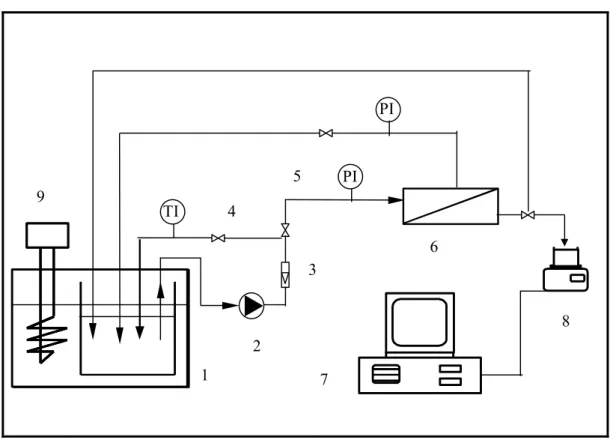
The flow diagram of the first experimental set-up is shown in Figure 3.1, this is a ND-2 membrane apparatus designed and built in Nanjing University of Chemical Technology, China. The membrane area of the laboratory cross-flow module was 35 cm2. The TZA 944 Test Rig with two units ready for operation was manufactured in Amafilter Membrantechnik GmbH, Germany. Its working principle was similar with that of ND-2, only the membrane surface of each unit was 44 cm2.
In the ND-2 set-up, the oil-in-water emulsion was stored in the tank (1) and pumped to the ultrafiltration cell (6) using a pump (2). This volumetric pump ensured a constant flow rate and thus constant velocity at the inlet of the ultrafiltration cell. The flow rate was monitored by the electromagnetic flowermeter (3). The concentrate was recycled in the tank. The pressure at the outlet of the module could be adjusted with a discharge valve (4). Two pressure transducers (5) measured the pressure at the inlet and outlet of the module in the concentrate compartment. To maintain a constant temperature, a thermostat (9) was placed in the tank. The evaluation of permeate mass versus time was measured by a balance (8). The voltage output of the balance was sent to a personal computer (7) that converted the signal into a flow rate and stored in disk files.
21
Chapter 3. Materials and Methods
feed tank
2
6
1
5 4
3
8
7 9
PI
TI
PI
1: Feed tank; 2: Pump; 3: Flowmeter; 4: Discharge valve; 5: Manometer; 6:
Membrane module; 7: Computer; 8: Balance; 9: Thermostat
Figure 3.1 ND-2 UF experimental set-up
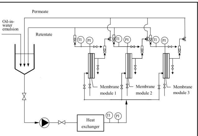
A schematic diagram of the batch pilot-scale MA-CO ultrafiltration unit operated in this study is shown in Figure 3.2. The unit equipped with industrial size spiral-wound ultrafiltration membrane modules placed in a stainless steel housing, feed and permeate tanks, feed sanitary centrifugal pump, recycle and permeate flow-meters etc.
Three modules of industrial size spiral-wound ultrafiltration membrane can be used simultaneously, or individually. Pressure data were from pressure transducers located at the membrane inlet and outlet. The recycled retentate and the permeate flow rates were measured by variable section flowmeters.
22
Chapter 3. Materials and Methods
Retentate
Heat exchanger Permeate
Oil-in- water emulsion
Membrane module 1
Membrane module 2
Membrane module 3
TI PI
TI PI
TI PI TI PI
Figure 3.2 Schematic diagram of pilot-scale unit
3.2 Investigated Membranes
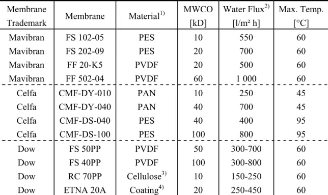
The experimental UF membranes in laboratory scale were produced in different companies included Mavibran FS and FF from Magyar Viscosa Corporation, Hungary; Celfa CMF DY and DS from Celfa Company, Switzerland; Filmtec FS, RC and ETNA from Dow Chemicals Membrane Group, Denmark and TS 6V 205 from Hoechst Company, Germany. Tables 3.1 and 3.2 show the physical and filtration properties of the membranes used. The membranes were chosen so that they would have different materials and cut-off values.
23
Chapter 3. Materials and Methods
Table 3.1 Properties of UF membranes in ND-2 set-up Membrane Material1) MWCO
[kD]
Water Flux2) [l/m² h]
Max. Temp.
[°C]
TS 6V-205 PES 100 800 60
FP 055 A PVDF 60-80 1 000 60
FS 202-09 PES 20 700 60
1: PES: polyethersulfone; PVDF: polyvinylidene fluoride.
2: Feed pressure 3 bar and temperature at 20°C.
Table 3.2 Properties of UF membranes applied in UTZ 944 membrane unit Membrane
Trademark Membrane Material1) MWCO [kD]
Water Flux2) [l/m² h]
Max. Temp.
[°C]
Mavibran FS 102-05 PES 10 550 60
Mavibran FS 202-09 PES 20 700 60
Mavibran FF 20-K5 PVDF 20 500 60
Mavibran FF 502-04 PVDF 60 1 000 60
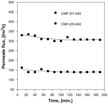
Celfa CMF-DY-010 PAN 10 250 45
Celfa CMF-DY-040 PAN 40 700 45
Celfa CMF-DS-040 PES 40 400 95
Celfa CMF-DS-100 PES 100 800 95
Dow FS 50PP PVDF 50 300-700 60
Dow FS 40PP PVDF 100 300-800 60
Dow RC 70PP Cellulose3) 10 150-250 60
Dow ETNA 20A Coating4) 20 250-450 60
1: PES: polyethersulfone; PVDF: polyvinylidene fluoride; PAN: polyacrylonitrile.
2: Feed pressure 3 bar and temperature at 20°C.
3: Regenerated cellulose.
4: Coated, hydrophilic.
Generally, fresh pieces of membrane were used with TZA 944 Test Rig test. For the experiments with ND-2 set-up, membranes were reused after each experiment, following an elaborate cleaning procedure. After each experiment, the emulsified oil/water solution was removed from the feed tank and pipelines. Then fresh tap water was placed into the feed tank and circulated through the membrane in 30 minutes.
After water circulation detergent solution, micellar solution with sodium dodecyl
24
Chapter 3. Materials and Methods
sulfate, n-pentanol and water were prepared in the feed tank and recycled through the membrane for 30 min. At the end of cleaning, tap water was fed into the feed tank, and the residual cleaning agent of the membrane was purged into the tank. Finally, distilled water was circulated through the membrane for 60 min, and permeate flux of pure water was determined. The cleaning procedure was repeated until the permeate flux of the cleaned membrane was similar to that of the virgin membrane (96-99%).
The pilot-scale unit was operated with three industrial spiral-wound membrane modules, denoted as TS-102, TS-202 and TS 502 manufactured by Zoltek Magyar Viscosa Corporation. TS-102, TS-202 and TS 502 membranes had a MWCO of 6-8, 15-20 and 55-65 kD, respectively. Both TS-102 and TS-202 membranes were constructed of PES (polyethersulfone). TS 502 membrane was made of PVDF (polyvinylidene fluoride) material. Each membranes had a transfer area of 5 m2, and their characteristics are given in Table 3.3.
Table 3.3 Properties of industrial spiral wound modules used in the pilot scale Membrane
type
Membrane area [m2]
MWCO [kD]
Min. PWF*
[l/m2h]
Max.
Pressure [bar]
Temperature [oC]
pH-ran ge
FS 10
(PES,TS-102) 5 6-8 1 000 8 60 1-13
FS 20
(PES,TS-202) 5 15-20 1 200 6 60 1-13
FF50
(PVDF,TS-502) 5 55-65 1 300 6 60 1-13
* pure water flux.
Before each experiments the standardization was measured with pure distilled water to give a reference (recycle flow rate: 3 000 l/h; feed pressure: 4 bar; temperature:
20oC; time: 1 hour). The permeate volume was measured in function of time.
3.3 Characteristics of the Applied Emulsions
For the laboratory experiments, the stable oil-in-water emulsion, HW-1, was obtained from Anhui Petrochemical Company, and was used without further purification. It contains engine oil, surfactants and deionized water. Two different concentrations of
25
Chapter 3. Materials and Methods
the oil-in-water emulsion were prepared in batches of 10 liters. Oil-in-water emulsions with oil concentration of 0.5 and 5 vol. % were used as feed solutions to the cross-flow filtration cell to foul the membranes. The flow rate of the feed oil-in-water emulsion, operating pressure and temperature were fixed at 200 l/h, 3 bar and 40 oC, respectively, for the duration of the experiments unless stated otherwise.
The permeate flux (l/m2h) of the membrane was measured by voluming the permeate conversed from the weight by the computer automatically. The emulsions produced were quite stable with respect to coalescence. Viscosity (η) of feed oil-in-water emulsion at 20oC was: η =1.381×10⁻³ N s/m2 at 5% feed concentration; η =1.139× 10⁻³ N s/m2 at 0.5% feed concentration. The viscosity of deionized water was 1.005× 10⁻³ N s/m2 at 20oC.
For the pilot-scale operation, the stable oil-in-water emulsion (c.a. 300 liters) was provided by Zoltek Magyar Viscosa Corporation and prepared by dispersing the engine oil with emulsifier in deionized water. The oil concentration in the feed emulsion was 0.5 vol. %. The emulsion produced was quite stable with respect to coalescence. The viscosity of feed emulsion at 20°C was η = 1.147×10⁻³ N s/m2. Tests were carried out at fixed temperature and transmembrane pressure. The experimental conditions were as follows: feed flow rate was 5 000 l/h, feed pressure 3 bar, temperature 40oC unless stated otherwise. The experimental selection criteria were established to facilitate performance of the pilot study in a number of different ways.
The transmembrane pressure and temperature operation criterion was set to reduce the risk of membrane integrity problems or irreversible fouling.
3.4 Methods of Measurements, Analysis and Elaboration
Transmembrane pressure was measured by manometer in the apparatus. The temperature of feed emulsion was monitored by thermocouple meter and controlled by heat exchanger automatically. The permeate flux was determined by volume from the permeate output.
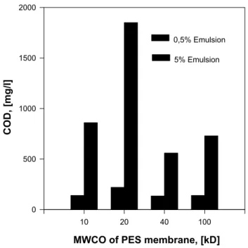
The methods of COD and oil concentration measurements were carried out according to Standard Method for the Examination of Water and Wastewater. The COD values (mg/l) were measured using the Hungarian National Standard MSZ 260/16-82 and National Standard of China GB 11914-89 in the individual experiments respectively.
The title of both measurement methods was Potassium Dichromate Method. Its principle is based on the amount of standard potassium dichromate solution consumed to oxidized the reduction matter in the sample water in the presence of strong acid.
26
Chapter 3. Materials and Methods
The excessive potassium dichromate was measured with the help of titration of standard ammonium ferrous sulphate solution. The calculation equation was shown as follows:
(
1 0)
32 8 10
) / ,
( = × − ×
Cr W
V V V l c
mg O COD
where c -- concentration of standard ammonium ferrous sulphate solution, mol/l;
V1 -- volume of standard ammonium ferrous sulphate solution used to titer sample water, ml;
V0 -- volume of standard ammonium ferrous sulphate solution used to titer pure water, ml;
VW -- volume of sample water, ml
8 -- molar weight of half oxygen (g/mol)
The oil concentrations (mg/l) were determined according to the Hungarian National Standard MSZ 260/22-74 and National Standard of China GB 12153-89 using Determination of Mineral Oil − Ultraviolet Spectrophotometry respectively. Its measurement principle is based on spectrophotometric analysis, because hydrocarbon has its specific absorption peaks in the ultraviolet range. Different concentrations of oily solution have various transmitting light performances. Thus a standard spectrophotometric calibrations curve can be plotted according to the transmitting light ability under different concentration of standard oily solution. The oil concentrations in the feed and permeate solutions were analyzed using UV spectrophotometer type SPECTROMOM 195 in Viscosa and UV spectrophotometer type SHIMADZU UV260 in China respectively. The calculation equation can be seen as follows:
VW
l m mg ion concentrat
Oil 1000
) /
( = ×
where m -- oil concentration based on the standard spectrophotometric calibrations curve, mg;
VW -- volume of sample water, ml.
The oil rejection coefficient (R) is defined as [TANSEL et al. 2001]:
27
Chapter 3. Materials and Methods
% 100 1 ×
−
=
R P
C
R C (3.1)
where R -- oil rejection coefficient, %;
CP -- the observed oil component concentration in permeate, mg/l;
CR -- the observed oil component concentration in retentate, mg/l.
The topography of membrane surface and compositions of fouling substances were analyzed with the help of Hitachi S-570 SEM and MAGNA-750 FT-IR with OMNIC data analysis system, respectively. The details can be seen in Chapter 4.2.
3.5 Methods of Mathematical Modelling and Data Acquisition
All of the pressures (inlet, outlet and permeate) were measured using pressure gauges.
The permeate and retentate flows were measured using the flowmeters equipped with conversion modules. The temperature was also recorded, using an electronic temperature probe connected to a thermistor. The flow and pressure transducers generated voltage signals that could be read and recorded by a computerized data acquisition system.
The pressure, temperature and permeate flux were continuously logged onto a Legend computer by an instrumentation and analysis program called LEASQ-Memb. These operation parameters were recorded in time. This program was configured in such a way as to control the operation of the ultrafiltration system as designed originally.
During the filtration runs, the computer calibrated and stored its input in a specified file. The stored data was later analyzed using Microsoft Excel 97 and then graphed using Origin 4.0 and Sigmaplot 5.0.
28
Chapter 4.1. Influences of Membrane and Process
Chapter 4
Results and Discussion
According to the experiments the processing of oil-in-water emulsions with conventional ultrafiltration membranes leads to concentration polarization, rapid membrane fouling and flux decline, and is generally uneconomic because of those problems. Therefore, the major hurdles to overcome in the development of practical industrial units are concentration polarization and membrane fouling. The factors which affect the concentration polarization and membrane fouling include the following three broad categories [THOMAS et al. 2000]:
Membrane type: the membrane material, pore size and distribution, and module configuration;
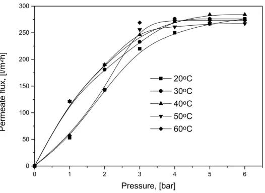
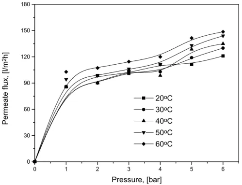
Operating conditions: factors such as pressure, temperature, cross-flow velocity and turbulence;
Solution characteristics: the nature of both solvent and solute, concentration and nature of the bulk fluid.
Although there have been many models to predict the effects of concentration polarization and membrane fouling presented by lots of researchers, among these results some are too complicated to have their values in practical application, and some introduce many boundary conditions.
This chapter discusses firstly the effects of different types of membrane (material, pore size and distribution, molecular weight cut off), feed oil concentration, transmembrane pressure, temperature in feed and other factors which influence the permeate flux, oil rejection and chemical oxygen demand (COD) in permeate. Then pilot-scale ultrafiltration experimental results are studied and compared with previous ones in a laboratory scale. The recovery performance of ultrafiltration membrane using different cleaning procedures is also compared and discussed. Finally, according to the above experimental results a model for estimating the gel concentration at the membrane surface and a mathematical model for membrane fouling were presented and identified. In case of our published results the sources are systematically mentioned in this chapter.
29
Chapter 4.1. Influences of Membrane and Process
4.1 Influence of Membrane Nature and Operation Parameters on Filtration Characteristics
4.1.1 Effect of membrane nature
4.1.1.1 Effect of membrane material
The interfacial property of membrane material and porous structure on the asymmetrical membrane surfaces are two important factors that influence the membrane separation [HU et al. 1996a]. The difficulty with emulsion is that after longer working the oil is accumulated at the membrane surface and may form a continuous layer which is usually named concentration polarization. The controlling mechanism for oil-in-water emulsion separation by UF is gel polarization [HU et al.
1996b].
The UF membrane studies have been focusing on the selection of membrane proper material and the preparation of membrane. The different membrane materials have different critical surface tensions and wettabilities. The preparation of membrane determines the MWCO, pore size and its distribution and so on.
Permeate flux is an important parameter to characterize membrane separation efficiency [WU et al. 1999]. With the development of polymer material science and technology, many kinds of polymer membranes have been invented or improved in order to increase permeate flux [ZAIDI et al. 1992]. In the present study, the effects of different membrane materials on the average permeate flux are shown in Table 4.1.1.
It can be found that the permeate flux of hydrophilic membrane (Celfa PAN) with the same nominal MWCO is much higher than that of hydrophobic membrane (Celfa PES) either at feed concentration of 0.5% or at 5%.
For an actual rejection and feed oil concentrations the decline in membrane permeate flux over a time period (minutes to days) is often accompanied by an increase in oil rejection, is attributable to a variety of mechanisms known as fouling. Fouling can be expressed in terms of the resistance to permeate flux observed at each stage of operation relative to the resistance of the clean membrane. PAN with hydrophilic group (−CN) has high permeate flux and high mechanical strength, as it was published [HU et al. 1996b]. With the same nominal MWCO, 40 KD, the permeate
30
![Table 3.3 Properties of industrial spiral wound modules used in the pilot scale Membrane type Membrane area [m 2 ] MWCO [kD] Min](https://thumb-eu.123doks.com/thumbv2/9dokorg/838029.43442/25.892.125.773.567.825/table-properties-industrial-spiral-wound-modules-membrane-membrane.webp)