** PhD, National University of Kharkiv, Ukraine. PhD, Harkovi Nemzeti Egyetem, Ukrajna. ORCID: 0000–0002–6285–3135 ÖSSZEFOGLALÁS: A gázturbinalapátok gyártásában a hőálló egykristályok
igen fontos szerepet töltenek be. Az egykristály ötvözetből készült lapátokat széles körben alkalmazzák repülőgépeknél, hajóknál és erőműveknél. Ezeknek a hőálló ötvözeteknek a modern alkalmazásokban szokásos alkalmazási hőmérsékletnél magasabb hőmérsékletet kell elviselniük, amelyet csak egy hatékony hűtési rendszerrel támogatva lehet megvalósítani. A gázturbinalapá- tok gyártása során széles körben az irányított kristályosítást alkalmazzák.
ABSTRACT: In gas turbine construction, heat-resistant single-crystal materi- als have taken a strong place. Single-crystal alloy blades are used in aircraft, ships, power plants, etc. Today, the temperature of the blades exceeds the temperature of heat-resistant alloys in normal operating conditions, and they can withstand such high temperatures only with the help of an effective cool- ing system. In the production of single-crystal blades of a gas turbine engine, the directional crystallization method has been widely used.
KEY WORDS: Gas turbine engine, single-crystal blade, azimuthal and axial orientation, crystallographic axis
KULCSSZAVAK: Gázturbina, egykristály lapát, azimuthális és axiális irány, kristálytani tengely
Berlizova Tetiana*
Modelling and numerical analysis
of structures made of single-crystal materials
i
ntroductionSingle-crystal blades are made of heat-resistant materials by directional crystallization. In real conditions it is quite difficult to achieve a complete coincidence of the crystal- lographic axes of the material with the axes of the blade itself. Therefore, the influence of the deviation of the crys- tallographic axes from the axes of the blade should be in- vestigated.
The use of directional crystallization makes it possible to form a structure in a crystal during casting that consists of columnar grains, the boundaries of which are mainly paral- lel to the directions of the main tensile stresses. When casting, the grain boundaries always have horizontal sec- tions arising due to the joining of the branches of second- order dendrites belonging to neighbouring grains. Figure 1.1 shows the growth structure of single crystals with crystallographic orientation <001> and <111> [2].
Single-crystal alloys can work at temperatures above 600 °C. A distinctive feature of single-crystal blades is that the destruction occurs in the direction of grain growth. The blades of gas turbines work not only at high temperatures, but at high flow rates as well. Therefore, the breakaway pieces of the blades with the gas flow can hit the engine elements, which can lead to reduced per- formance [7].
Figure 1. Dendritic structure of a single crystal: a) - <001>, b) - <111> [7]
a) b)
The structure of a single-crystal material with <001> ori- entation consists of first-order dendritic branches that are parallel to the crystallographic direction <001>. The
branches of dendrites are oriented along the heat flux and they are constructed in rows along the <010> and <100>
planes. They are developed along almost the entire length, in contrast to the second-order branches, which are lo- cated transversely from the heat flux. A single-crystal ma- terial with <111> orientation does not have dendritic branches and it is mainly developed in one direction, as in a single-crystal structure with the crystallographic direction
<001>. This is due to the fact that this sample was grown under conditions of a flat microscopic front. When such a single crystal grows in the same direction <001>, there is a continuous alternation of the axes or a transition of the first order axes in the second order axis and vice versa [7]. As a result, a material with a dendritic structure of this type gets a structure like a three-dimensional grid. That allows one to get the size of the element corresponding to the interdendritic distance.
The stationary heat conduction problem also has to be considered, which can be accomplished by solving the variational equation dJ = 0 for the functional [6]
J Tx
Ty
Tz dxdydz h T T dS
21 12
( ) V
k k
k S k
2 2 2
2
k
2 2
2 2
2 m 2
= + + +
+ -
b c
^ b
l m
h
; lE
/
###
##
, (1)where V is the volume of the body;
Sk - surface of blade portions and cooling channels;
hk - heat transfer coefficient in areas of the blades;
k - number of sections of the surface of the blade and its cooling channels.
The heat conduction process is described by a nonlinear partial differential equation. In a general case, the determi- nation of the temperature state of a cooled blade is a boundary-value problem of mathematical physics in three- dimensional space. The heat conduction process is de- scribed by a nonlinear partial differential equation [2]
dtd]tcTg=div grad^m Th+Q, (2) where T – temperature;
m - coefficient of thermal conductivity;
c - specific heat;
Q - characteristic of an internal source or runoff;
t - blade material density;
t - time.
This blade has a temperature difference both in the lon- gitudinal direction and in cross sections. Therefore, the task should be solved as three-dimensional. The varia- tional equation dJ = 0 for the functional (1) reflects the heat equation and boundary conditions of the third kind. These conditions are of the form [5]
S K
s s s
s s s
s s s
s s
s
1 11 12 13
12 22 12
13 12 33
44 55
66
= - = R
T SS SS SS SS
V
X WW WW WW WW
, (3)
where K - stiffness matrix
Sij - compliance matrix coefficients, which can be repre- sented as technical elastic constants [5]
S K
E E E
E E E
E E E
G G
G 1
1 1
1 1
1
x
y yx
z zx
x xy
y
z zy
x xz
y yz
z
xy
yz
xz 1
o o
o
o o o
= =
- -
-
- - -
-
R
T SS SS SS SS SS SS SS SS
V
X WW WW WW WW WW WW WW WW
(4)
with corresponding equations
Ex E
xy y
o oyx
= ;
Ez E
zx x
o oxz
= ;
Ez E
zy y
o oyz
= , (5)
where Ex, Ey, Ez are the modulus of elasticity under tension or compression in the direction of the axis indicated in the index;
Gxy, Gyz, Gxz - shear modulus (double indices correspond to the axes between which during the shift there is a change in the right angle);
oxy, oyz, oxz are the lateral strain coefficients in the direction of the second axes indicated in the index under normal stresses in the direction of the first axis.
The dependence of the coefficients of the compliance matrix (3) on temperature T for a single-crystal blade can be represented as
s h h h T
s h h h T
s h h h T
11 11 12 13 2
12 21 22 23
2
44 31 32 33 2
= + +
= + +
= + +
, (6)
where hij - coefficients determined for a particular material [5].
The polar graph shows the technical constants of the material (E1,E2 and G12), rotated in an angle from 0 - 360 degrees. This graph describes the anisotropy of the mate- rial and the influence of the orientation of the crystallo- graphic axes [1, 8].
g
eometricfeAturesofAsingle-
crystAlcooledblAde In the present paper, the cooled single-crystal blade with an efficient but complex vortex cooling system is studied (Figure 3). There are channels for the exit of cooling air, which are located near the exit edge to provide the exter- nal membrane cooling for the rather thin exit edge. The resulting temperature field with high temperature gradient causes the thermal expansion of the blade and high ther- moelastic stresses. Therefore, it is necessary to solve the interrelated task of determining the temperature and ther- moelastic state of cooled single-crystal blades [4].A
nAlysisofthestress-
strAinstAteofAsingle-
crystAl blAdeofAgAsturbineengineFor the steady thermal analysis of a cooled single-crystal blade, it is necessary to adapt the initial input data and the physical model of the object, taking into account that the Figure 2. Change in the technical constants of anisotropic material in the polar coordinate system [1, 8]
Figure 3. Cooling blade; labelled the single-crystal axes (a) and its cooling system in the form of a vortex matrix (b) [9, 10]
a) b)
characteristics are set continuously depending on the tem- perature of each area and have a discrete character. This was confirmed in the analysis of the free vibrations of the blade [8, 9]. In this case, knowledge of only elastic con- stants and density over regions was required. Given that the elastic constant changes were relatively small (Table 1), and density was practically unchanged, such model was quite satisfactory. When solving the
problem of thermoelasticity, it is neces- sary to take into account the fact that the temperature field undergoes dis- continuities; therefore, setting the tem- perature equal in each region is unac- ceptable. In an area where the temper- ature is the same, temperature stresses do not occur. At the same time, large bursts of temperature stresses will ap- pear at the boundaries of regions with different temperatures. However, nei- ther of the two cases reflect the actual thermally stressed state of the blade. In this regard, it is necessary to adapt the temperature field so that the tempera- ture change occurs continuously. The structure of a single-crystal alloy is a face centered cubic lattice. A distinctive
feature of such a structure is that when it is rotated 90°
around any of the axes, the elastic properties of the mate- rial are preserved, and when rotated to a different angle which is not a multiple of 90°, they change. With an arbi- trary orientation of the single crystal, the compliance matrix is completely filled. However, if the axes of blade x, y, z coincide with the crystallographic axes of material <100>,
<010> and <001>, it has a simplified form and contains only three independent elastic constants. In the most gen- eral case, a blade made of a single-crystal alloy with an arbitrary orientation of the crystallographic axes is consid- ered an anisotropic body. In this work, the elastic charac- teristics of the material have been used, taking into ac- count the temperature state of the blade.
For a preliminary analysis of the blade, the stress-strain state was calculated under the action of centrifugal forces (at a temperature of 20 °C) and a rotational speed of 7790 rpm (or 815 rad/s). Figure 4 shows the results of the calcu- lations.
Also, at the preliminary calculation stage, an analysis of the influence of the temperature field was carried out (Fig- ure 5). During the calculations, convection heat exchange was taken into account. As mentioned earlier, the working gas temperature was 800 Celsius, while the temperature of the cooling air that entered the cooling channel was 600 degrees. The cooling air rising from the root of the scapula gradually heated up. The data on the distribution of the temperature field is presented below.
The greatest temperature gradients were observed on the surface of the cooling channels. As a result of this tem- perature difference, stress concentrations occurred on the surface of the cooling channels.
Next, calculation was carried out taking into account the temperature field. The task of thermoelasticity was solved together with the task of static deformation under the influ- ence of centrifugal forces. The data on the distribution of the intensities of static deformations over the volume of the blade and in different sections under the influence of op- erational loads is shown below.
Below is a graph (Figure 7) comparing the stress-strain state of a single-crystal blade with the effects of work loads and without them. Curve 1 describes the maximum values of equivalent stresses and strains without taking into ac- count the influence of the temperature field (at t = 20 °C).
Curve 2 shows the dependence of strain and equivalent stresses on operating temperatures (600 - 800 °C).
A comparison of the stress-strain state of a single- crystal cooling blade at a temperature of 20 °C and an Figure 5. Distribution of the temperature field over the surface of the blade and in the longitudinal and transverse sections
Figure 4. The distribution of stress over the blade Table 1. The value of elastic constants for different temperature areas
T, °С
The value of elastic constants at different temperatures
E, MPa o G, MPa
20 °С 139607 0,3833 129524
600 °С 115057 0,421 107061
650 °С 112561 0,423 105223
700 °С 110032 0,425 103366
750 °С 107483 0,427 101496
800 °С 104922 0,428 99618
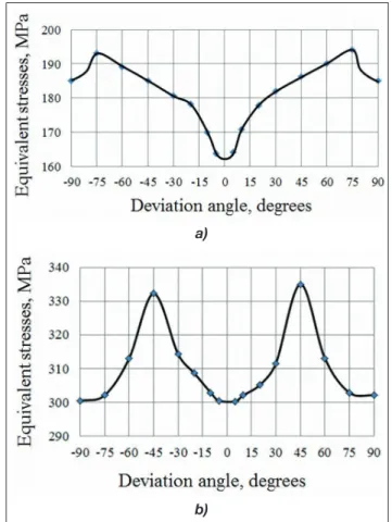
operating temperature of 600 - 800 °C shows that the temperature field has the main effect on the stress-strain state. The influence of the deviation of the crystallograph- ic axes of a single-crystal material from the blade’s axes on the stress-strain state of the blade was also analysed in the work. The location of the inlet and outlet edges is shown in Figure 8. The data obtained is presented in graphs (Figure 9).
When the orientation of the crystallographic axes chang- es, all stresses are redistributed and the whole picture of the stress-strain state of the blade changes. Since the larg- est equivalent stresses can be present in a new area of the blade, they will also depend on the geometric features of this area and its temperature.
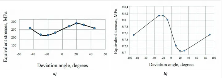
The change in the maximum and minimum stresses over the volume of the blade is shown in the graphs below (Fig- ure 10).
The distribution of maximum stresses at the inlet and outlet edges does not exceed the maximum stresses over the volume of the blade. It can be seen in Fig. 8 and Fig. 9 that the distribution of the stresses is cyclical.
The effect of the rotation of the crystallographic axes on the distribution of equivalent stresses on the surface of the blade (in the xy plane around the z axis, which corresponds to the crystallographic axis <001>) is illustrated by Figure 11. The orientation of the crystallographic axes signifi- cantly affects the distribution of stress fields. The crystal- lographic axes <100>, <010>, <001> in this case coincide with the axes of the blade x, y, z. Figure 11 shows the re- striction on the rotation of the crystallographic axes by angles { ≤ 15° and } ≤15° [3].
Figure 7. Dependence of strains and equivalent stresses on the temperature field
Figure 8. Location of the inlet and outlet edges
Figure 6. Distribution of equivalent stresses over the volume of the blade in longitudinal and transverse sections
Figure 9. Change in equivalent stresses at the input (a) and outlet (b) edges of the blade during rotation of the crystallo- graphic axes of the material relative to axis <001>
a)
b)
c
onclusionsThe necessity of using three-dimensional mathematical models for analysing the thermoelastic state of a single- crystal blade with the orientation of the crystallographic axes has been confirmed.
It is necessary to take into account the continuous varia- tion of the temperature field, which makes it possible to detect bursts of temperature stresses at the boundaries of regions with different temperatures.
A comparison of the stressed - deformed state of the blade without taking into account the temperature field and under the influence of the operating temperature has been performed.
In an inhomogeneous temperature field temperature stresses arise, which are distributed unevenly over the volume of the blades. In a number of cases, a concentra- tion and localization of stresses on the surface of the chan- nels for the exit of cooling air occurs.
Deviations of the crystallographic axes of the material in the xy-plane should not exceed 12° - 15°.
r
eferences[1] C. E. Anderson, P. A. Cox et. al. Constitutive Formulation for Anisotropic Materials Suitable for Wave Propagation Computer programme-II, Comp.
Mech, 15, (1994), 201 – 223.
[2] K. Bate, E. Vilsan, Numerical analysis methods and the finite method elements, Moscow: Stroyizdat, 1982, 448 p.
[3] T. Yu. Berlizova, Yu. S. Vorobiev, N. Yu. Ovcharova, R. Rzadkowski, The Influence of Azimuth Orientation of Crystallographic Axes on Thermoelastic State of a GTE Blade with a Vortex Cooling System // Strength of Materials. 2016. Vol. 48. P. 349–356.
[4] T. Yu. Berlizova, Thermal stress state of a cooled single-crystal blade of a gas turbine engine, with the azimuthal orientation of the crystallographic axes, Improving turbine installations using methods mathematical and physical modeling: International Scientific and Technical Conference, Kharkov:
IPMash NAS of Ukraine, 2015, 1–7.
[5] I. A. Birger, B. F. Shorr, G. B. Iosilevich, Strength calculation machine parts, Moscow, 1979, 702 p.
[6] Yu. S. Vorobev, B. F. Shorr, The theory of twisted rods, 1983, 186 pp.
[7] E. N. Kablov, V. N. Tolorayya, I. M. Demonis, N. G.
Orekhov, Directional crystallization of heat resistant nickel alloys, Light alloy technology, 2, (2007), 246 – 264.
[8] M. Palantera, Theoretical Background of ESAComp Analyses, 1998.
[9] R. P. Pridorozhnyy, The influence of crystallographic orientation single-crystal materials for the stress state of the working blades turbines, Dissertation, Zaporozhye, 2008, 223 p.
[10] R. P. Pridorozhnyy A. V. Sheremetyev, Influence crystallographic orientation to volumetric stress- strain state of a single-crystal uncooled turbine blade, Bulletin engine building, 1, (2003), 47–51.
(Illusztrációk a szerző gyűjteményéből)
Figure 11. Scheme of limitations on the deflection of the crystallographic axes of the material from the blade axes
Figure 10. Change in maximum (a) and minimum (b) equivalent stresses
a) b)
A
dAtpontosításA Haditechnika 2020/5. számában jelent meg Farkas Zoltán: Új típusú nehézgépszállító szerelvények című tanulmánya. A cikkben bemutatott kétsebességű Sepdurance H200 típusú csörlőmű fel- és lecsévélési sebessége – a beállítástól függően – az alsó, illetve felső kötélágon az 5 m/min, illetve a 21 m/min sebességet teszik lehetővé – Szerk.
![Figure 1. Dendritic structure of a single crystal: a) - <001>, b) - <111> [7]](https://thumb-eu.123doks.com/thumbv2/9dokorg/772338.34638/1.854.80.438.693.820/figure-dendritic-structure-single-crystal-lt-gt-lt.webp)
![Figure 3. Cooling blade; labelled the single-crystal axes (a) and its cooling system in the form of a vortex matrix (b) [9, 10]](https://thumb-eu.123doks.com/thumbv2/9dokorg/772338.34638/2.854.422.774.96.467/figure-cooling-labelled-single-crystal-cooling-vortex-matrix.webp)