Reduction of the effect of actuator saturation with periodic servo-constraints
L´aszl´o Bencsik, L´aszl´o L. Kov´acs
MTA-BME Research Group on Dynamics of Machines and Vehicles Budapest, Hungary
{bencsik, kovacs}@mm.bme.hu
This manuscript is identical with published version.
ABSTRACT
Saturation is an undesired event in trajectory tracking control of mechanical systems. When the actuators of a robotic device saturate the solution of the inverse dynamics problem cannot fully be
realized, which results in deviations from the desired trajectory and loss of performance. It is generally hard to consider the limited actuator torques and the corresponding nonlinear effects in the
control design. The most common way to handle the problem is recalculating the control forces and trying to adjust the desired trajectory such that saturation will not happen. In contrast we propose a switched control approach, where, upon saturation, a periodically switched input is applied to keep the
reference point of the robot on the desired trajectory. For this, the desired motion is formulated by means of servo-constraints, and the periodic switching of these constraints is adjusted according to the variation of a new, manipulability type performance measure. It will be demonstrated that the proposed adaptive controller can reduce the undesired effects of actuator saturation effectively. An example is provided to show the application of the method and to compare the results with those of
other methods taken from the literature.
keywords: Computed torque control, actuator saturation, periodic servo-constraints, manipulability measure, multibody dynamics
1 INTRODUCTION
Actuator saturation occurs when the controller’s output exceeds the physical limit of the actuators of a system. In this case the controller can no longer properly realize the desired motion, and as a result, large overshoots and sustained oscillation may develop. These increase the settling time and
potentially can lead to an unstable motion.
In structured, industrial environments saturation can be prevented by careful trajectory planning based on the well defined task and operational conditions. The use of large, powerful actuators is often also an option. When these are not possible, e.g., in field and service robotics [1] where the environmental conditions and the task are a priory unknown, saturation can result in poor dynamic
performance.
Performance deterioration resulting form saturation is often called actuator windup [2], and the control methods trying to minimize the undesired effects of saturation are commonly referred to as
anti-windup techniques [3, 4, 5]. These techniques were originally developed for linear single-input single-output systems [6]. A possible generalization to non-linear multi-input multi-output systems is
shown in [7] by using partial feedback linearization. A method that is directly applicable to non-linear mechanical systems is presented in [8].
For trajectory tracking of robots, feedback linearization essentially gives the same control forces/torques as the classical computed-torque control method. Therefore, it is clear that when saturation happens, feedback linearization cannot cancel all the nonlinear dynamic terms [7] and the robot will deviate from the desired trajectory. A common element of the anti-windup control schemes
is that the saturating control force is compared to the ideal control force, and based on this, the input of the controller is modified to reduce trajectory following error.
Instead, in our approach we aim to redistribute the load of the saturating actuator(s) among those which are still functioning in their nominal operating range. This is feasible in robotic systems where
typically only a few, but different actuators saturate as the robot follows the commanded end-point
trajectory. Often there are also more actuators available than what the task would require. For example, when cooperating robots are moving an object [9]. Still, depending on the number of
saturated actuators, these robots can loose their ability to realize the desired task without redistributing the load on the actuators. In case of a single robot with as many actuators as the task
requires, saturation will limit the control capabilities similar to those of the trivially underactuated system with fewer actuators than degrees-of-freedom.
In reference [10], upon saturation the controlled robotic system is considered temporarily underactuated, and a servo-constraint based controller [11, 12, 13] is implemented to distribute the
load on the actuators differently with and without actuator saturation. In the saturating phase, a reduced, linearly combined set of servo-constraints is used to minimize the trajectory following error.
This is somewhat similar to the method proposed in [7], where the control force is recalculated by preserving the direction of the control action without saturation.
The present paper introduces a periodically switched controller which not only reduces the number of servo-constraints, but also adapts to the dynamics of the system during saturation. The periodic switching makes it possible to regulate all the original servo constraint over time, one after the other,
and it also helps to stabilize the internal dynamics of the temporarily underactuated system [14]. It will also be demonstrated that a new performances measure, similar to dynamic manipulability, can
effectively be used to algorithmically choose and update the periodic control input.
2 DYNAMIC FORMULATION
2.1 Equation of motion
In modelling the dynamics of complex multibody systems the use of a non-minimum set, descriptor type coordinates is quite common [15]. In this case, the general form of the equation of motion is
M¨q+ΦTλ+c=Q+Hu, (1)
φ(q, t) =0, (2)
whereqis the array ofndependent coordinates, andφcollects themgeometric constraints associated with the coordinates selected. MatrixMis the mass matrix,Φ(q, t) =∂φ/∂qis them×n
Jacobian of the constraints, andλis the array of Lagrangian multipliers corresponding to the constraints. Arrayc(q,q, t) contains the Coriolis and centrifugal terms and˙ Q(q) denotes external
forces other than the control inputs, such as gravity. The forces/torques of the actuators are represented by thel×1 arrayuandH(q) is then×l control input matrix.
Equations (1) and (2) form a differential algebraic system of equations (DAE) with differentiation index 3. There are direct methods for solving these equations, but very often the method of Lagrange
multipliers is used [15]. This method reduces the differentiation index to 1 by expressing the constraints at the acceleration level as
φ¨ =Φ¨q+ ˙Φq˙ + ˙ϕ, (3)
whereϕ=∂φ/∂t, and makes it possible to express the equation of motion in the form
M ΦT Φ 0
q¨ λ
=
Q−c+Hu
−Φ˙q˙−ϕ˙
. (4)
From Eq. (4) the accelerations ¨qand the Lagrange multipliersλcan be computed, and the integration forqcan be carried out by a suitable method (e.g., trapezoidal rule).
2.2 Motion specification and inverse dynamics
One can define the desired trajectory of a robot, by adding a second set of constraint equations, the so-called servo - or actuator constraints, to equations (1) and (2) [11, 16]. These are mathematically
equivalent to the geometric constraints, however, the fact that these do not belong to physical interconnections of bodies makes an important difference. The servo-constraints, for example can describe the tool-center-point (TCP) trajectory of the robot, and the violation of these constraints is
proportional to the tracking error. The violation of the geometric constraints is a measure of the accuracy of the numerical simulation only.
Servo-constraints represent also a useful tool for solving the inverse dynamics. This can be done similarly to the solution of Eq. (4) for the Lagrangian multipliers. In order to show this, let us
consider the servo-constraints in the general form
γ(q, t) =p(q)−h(t) =0, (5)
wherep(q) describes the output, e.g., position and orientation of the TCP of a robot, as function of the generalized coordinates, andh(t) is the desired output with explicit time dependence. The servo
constraints can also be expressed at the acceleration level as
¨
γ=Γ¨q+ ˙Γq˙ −g˙ , (6)
whereΓ=∂p/∂qis the Jacobian associated with the servo-constraints andg=∂h/∂t. Also, the control inputuplays a similar role as the Lagrangian multipliers associated with the geometric constraints. It enforces the servo-constraints just like the physical structure of a system enforces the
geometric constraints through the development of constraint forces described by Lagrangian multipliers. Therefore Eqs. (1), (3) and (6) can be combined in the compact form
M ΦT −H Φ 0 0 Γ 0 0
¨ q λ u
=
Q−c
−Φ˙q˙−ϕ˙
−Γ˙q˙ −g˙ −η
, (7)
where η(q) is a feedback control term. Whenη=0, then the solution of the system in (7) gives the control forceufor the desired motion defined by the acceleration level servo-constraints. When the
calculated control force is used in a feed-forward loop, this is called the computed torque control (CTC) method. To compensate for disturbances and modelling errors the feedback term may be chosen asη=KDγ˙ +KPγ, whereKP andKD are the proportional and derivative control gains,
respectively. This control action is similar to the Baumgarte stabilization [17] widely used in dynamic simulation of multibody systems.
Given a motion specification, Eq. (7) can be solved for the required control efforts as long as there are enough non-saturating actuators to realize the desired motion. This is true for most of the fully
actuated mechanical systems, but underactuated systems and systems with higher relative degree may require a special treatment [11, 18]. When one or more actuators saturate, the solution of Eq.
(7) does not provide a feasible control force. Then only a subset of the original servo-constraints can be enforced by the remaining non-saturating actuators, and the system becomes temporarily
underactuated with respect to the original task.
3 PERIODIC SERVO CONSTRAINTS
The basic problem in implementing a computed torque controller for systems with input torque saturation is that some states of the system will evolve uncontrollably during saturation. The dynamics associated with these uncontrolled states is referred to as the internal dynamics of the
q,q˙ ud yes
u
no
usat,Qsat
γ
γsat(t) =γsat(t+T)
Mechanical system
Computed torque control
Saturation detection
Periodically switched control Trajectory
planning
Servo- constraints
Periodic Constraint
Selection
γ
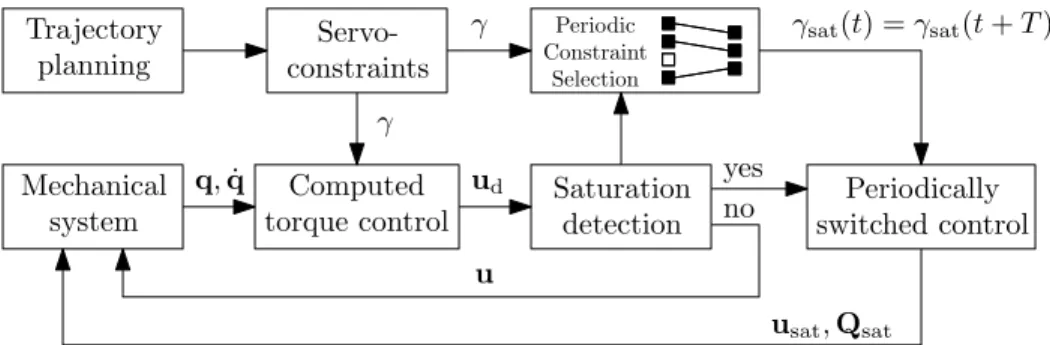
Figure 1: Block diagram of the proposed controller
system. It depends not only on the physical properties and the load of a system, but also on the selection of the controlled variables. Also, it can be unstable in which case the utmost control objective is to find a stabilizing controller. This may be achieved by slightly changing the controlled
reference point by modifying the servo-constraints, or altering the structural properties of a robotic device [12, 11, 13].
Considering sufficiently strong dynamic coupling, a different approach is to implement a switching controller that switches between two or more sets of servo constraints such that the internal dynamics remains stable and the desired trajectory is realized within tolerances. The switching can
be tied to certain events or done periodically with time. In the followings, we will use periodic feedback, the stabilization effect of which is well known in case of time delay system [19]. These
systems has infinitely many poles, but only a few actuators.
A periodically switched controller was successfully applied for the trajectory tracking of an underactuated service robot in our previous work [14]. It that paper the switching pattern and period were determined based on numerical stability analysis and simulations which makes the online
implementation difficult. Instead, here we propose a method which rely only on the actual state of the system, and adjusts the parameters of the periodically switched controller continuously on the
course of operation.
The general idea is outlined in Fig. 1. It shows that until saturation occurs the classical computed
torque controller is applied. Then, the number of servo-constraints is appropriately reduced, different sets of servo constraints are formed, and these are combined into a new periodic servo-constraint signalγsat(t) =γsat(t+T) with periodT. One possibility to do this is to take the linear combination
γsat =
N
X
i=1
αibγi with αi(t) =αi(t+T) (8)
where arrayγbi contains a reduced set of servo-constraints withr < lelements, coefficientsαi control the switching between the different sets of servo constraints, andN < lr
is the number of the considered different sets. Figure 1 also shows that during saturation a reduced size,r×1, control
inputusat is considered and the effect of the saturated actuators is represented by the constant external force termQsat. With these, and using the subscriptsat to denote the terms affected by
saturation, equation (7) can be rewritten as
M ΦT −Hsat
Φ 0 0
Γsat 0 0
¨q λ usat
=
Q+Qsat−c
−Φ˙q˙ −ϕ˙
−Γ˙satq˙ −g˙sat−KDγ˙sat−KPγsat
. (9)
For a given reduced set of servo-constraintsγsat, the required control inputsusat can be calculated based on this equation. For the selection and switching between different, reduced sets of servo-constraints, a manipulability type performance index is proposed. The performance index is
evaluated at certain time instants and a periodic control signal is formed such that more time is allocated for the sets with the higher indices. This way, those servo-constraint sets are prioritized
where there is a stronger coupling between the control inputs and the desired accelerations.
The proposed performance index can be introduced by considering the minimum coordinate parametrization of the equation of motion in (9) as
BTMB¨p+MB˙p˙ +BT(c−Q−Qsat) =BTHsatusat, (10)
where transformation ˙q=Bp˙ defines the new parametrization. Note, thatpis conveniently selected as the array of operational space coordinates, the evolution of which are directly prescribed by the
servo-constraints. Then, neglecting external forces other than the control input, the linearised equations become
M
¨
p−M−1BTQsat
=BTHsatusat, (11)
whereM=BTMBis the operational space mass matrix [20], and ¨p−M−1BTQsat is the acceleration due to the non-saturated actuators. By denoting this acceleration with¯a and introducingG=BTHsat, the uniformity of thecontrol input to acceleration gain is given by the
manipulability ellipsoid
¯
aTM¯a≤1 with M= G†MT G†M
, (12)
whereG† is the Moore-Penrose pseudo-inverse ofG. Also, letei be anl dimensional unit vector, containingrnon-zero elements associated with a certain reduced set of servo-constraints. With this,
the effect of the control input in a specificdirection can be characterized by the performance index
zi= 1 q
eTiMei
, (13)
and the time to be devoted to the realization of the considered set of servo-constraints within one control period may be obtained as
∆ti= ziT PN
j=1zj
(14)
Equations (13) and (14) help to find aphysically motivated periodic control signal. This needs to be updated in the course of the motion by considering the current state of the system, or, in off-line
l1 l2
θ1
θ2
x y
m1
m2
O
A
TCP
τ1
τ2
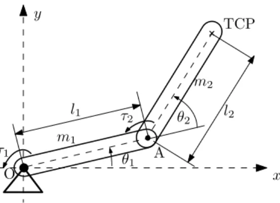
Figure 2: Two-link planar manipulator
calculations, the desired values of the servo-constraints.
4 EXAMPLE
In the following, as the simplest non-trivial example, we consider the trajectory tracking control of a two-link manipulator. This is similar to the anti-windup control problem of a SCARA robot
analyised in [8].
The system shown in Fig. 2 has two identical links withl1=l2= 0.4 m and m1=m2= 0.2 kg . A homogeneous mass distribution is considered, and the configuration is described by the independent
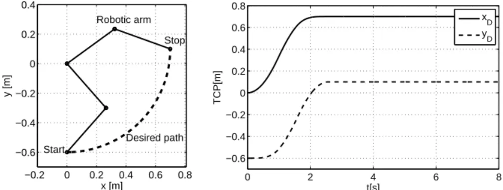
generalized coordinatesq= [θ1, θ2]T. The manipulator is in the horizontal plane, and its TCP (tool-center-point) is required to follow a circular trajectory with a trapezoidal velocity profile. This
is shown in Fig. 3 where the base joint of the manipulator is located in the origin, and the circular trajectory is centered atx= 0 andy= 0. The maximum values of the acceleration and velocity for
the trapezoidal velocity profile areamax= 0.7 m/s2 andvmax= 0.7 m/s. The corresponding operational space trajectories,xD(t) andyD(t), are shown in Fig. 3. The saturation limit of the shoulder motor isτ1 max= 0.6 Nm, and it is assumed that the second actuator,τ2, will not saturate.
In addition, parametersKP andKDin (9) are set to 40 N/m and 30 Ns/m, respectively.
For the considered simple manipulator it is straightforward to derive the equation of motion in operational space coordinatesp= [x, y]T. Because of the initially chosen independent set of relative coordinatesq= [θ1, θ2]T, there is no need for geometric constraints, and the transformation matrixB
in (10) is simply the inverse of the manipulator Jacobian. Also, for inputu= [τ1, τ2]T, the control input matrix His the identity matrix. Taking these into consideration, and assuming that only the
shoulder motor with the higher loads will saturate, the components of the linearized equation of motion (11) are
M=
m11 m12
m21 m22
, B=
b11 b12
b21 b22
, p¨ =
¨ x
¨ y
, Qsat=
τ1max
0
, Hsat=
0 1
and usat =τ2, (15) where, for the sake of brevity, the elements ofMand Bare only indicated by single symbols. In
addition, the circular trajectory shown in Fig. 3 is defined by the servo-constraints
γ(p(q),t) =
l1cos(θ1) +l2cos(θ1+θ2) l1sin(θ1) +l2sin(θ1+θ2)
−
xD
yD
, (16)
wherexD(t) andyD(t) define the desired motion of the TCP of the manipulator. Note, that in the acceleration level equation (6) matrixΓ=∂p/∂qis precisely the manipulator Jacobian. It can be also seen that, during saturation, only the remaining single actuator,τ2, can be used to realize both
servo-constraints.
By having a planar motions specification, one can either considerγ1 orγ2 as single elements of two differentreduced setsof servo-constraints. According to (8), these different sets can be combined
in a single expression as
γsat=αbγ1+ (1−α)bγ2 (17)
−0.2 0 0.2 0.4 0.6 0.8
−0.6
−0.4
−0.2 0 0.2 0.4
x [m]
y [m]
Start
Stop Robotic arm
Desired path
0 2 4 6 8
−0.6
−0.4
−0.2 0 0.2 0.4 0.6 0.8
t[s]
TCP[m]
xD
yD
Figure 3: Desired path (left) and corresponding TCP trajectories (right) α
t
∆t1 ∆t2
4T
update switching
1
0
∆t01 ∆t02 (duty cycle)
Figure 4: Switching function for periodic servo-constraint realization
where now bγi≡γi, i= 1,2 , and the periodic functionα(t) =α(t+T) controls the switching between these servo-constraints. In the current example, this is realized such that each period include 20 integration time steps (h= 0.01 s), and the duty cycle of the switching functionα(t) is updated after every 4th period as it is illustrated in Fig. 4. Note, that the update frequency is a free
control parameter which needs to be tuned by simulation or can be selected empirically. The switching between the control objectives represented by each reduced set of servo constraints is
however algorithmically defined by equation (14). For the two-link manipulator example, this
equation gives the duty cycle parameters, ∆t1 and ∆t2=T−∆t1, as follows
∆ti= ziT z1+z2
, i= 1,2 with z1= b221+b222
|b21m11+b22m21| and z2= b221+b222
|b21m12+b22m22| , (18) wherezi= eTiMei
−1/2
, and unit vectorse1= [1,0]Tande2= [0,1]T represent the different servo-constraint directions.
When there is no actuator saturation, the required control input can be determined based on equations (7) and (16) by disregarding the unnecessary geometric constraints. During saturation, equations (9) has to be considered with the terms defined in equations (15) and (16), and using the
periodic servo-constraints given by equations (17) and (18). Simulation results obtained with this proposed control scheme are compared to those of the classical computed torque control in Fig. 5. It
can be seen that both methods have simultaneous, but different magnitude, peaks in the constraint violations. The periodic controller seems to outperform the other in the second half of the
simulation, and the system recovers from the saturation slightly faster when periodic servo-constraints are applied (seeτ1 in Fig. 5). When the norm of the servo-constraint violation is
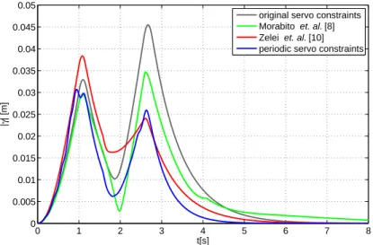
considered, the better performance of the periodic controller is obvious. This is shown in Fig. 6 where the results obtained with two other methods available in the literature are also presented.
The method proposed in [10] is similar to ours in the sense that when saturation happens a reduced set of servo-constraint is constructed, which is then used until the system recovers from saturation.
The main difference between this and our approach is the periodic variation of different reduced sets of servo-constraint as opposed to using only one. Also, in the present paper we propose an algorithmic approach to select to which extent the different sets of servo-constraints, representing different control objectives, are considered in the periodic control signal. In Fig. 6 it is shown that the
two methods perform similarly in the beginning and at the end of the simulated motion, but the use of periodic servo-constraints could considerably reduce the trajectory tracking error in the middle.
This is the part of the trajectory which changes the most (see Fig. 3). We also note that the results
are directly comparable as [10] does not require any additional control parameters to be defined.
As a second method to compare with, let us consider the anti-windup control scheme presented in [8].
Among the many general purpose anti-windup schemes, this one is specifically developed for Euler-Lagrange systems. It is well suited for robotic mechanical systems, which makes the comparison clearer. For the implementation of the method, in the present example, three additional
control parameters had to be chosen. By keeping the notations of the referenced paper, these anti-windup design parameters areKg= 0.99,Kq = 10 andK0= 1. ParameterKg is selected to the
same value used in [8] in a similar example, while the PD type control gainsKq andK0 were tuned empirically to achieve a nearly optimal performance. This method and the use of periodic servo-constraints results in similar results almost in the entire course of the motion, but the periodic
controller shows a much better convergence to the desired zero steady state error.
When the tracking error of the four different methods are compared, Fig. 6 suggest that the best results can be achieved with the method of periodic servo-constraints. This is confirmed by the RMS
(root-mean-square) values presented in Tab. 1. It is clearly shown that the methods in [10] and [8]
has a very similar performance, while the method of periodic-servo constraints gives both the lowest peak - and average tracking errors. With respect to the use of the original servo-constraints, and the
other two methods, the average tracking performance is improved by 19% and 21%, respectively.
CONCLUSIONS
There are three main contributions in this work. The first is the systematic introduction of periodic servo-constraints for the control of temporarily underactuated, saturated robotic systems. The proposed method successfully combine the stabilizing effect of periodic controllers with the need of
satisfying, and prioritizing between, different control objectives.
The second contribution is the introduction of a new, manipulability type performance measure for the algorithmic selection of a suitable periodic control signal. The proposed method is generally
0 2 4 6 8
−0.1
−0.05 0 0.05 0.1
t[s]
τ1 [Nm]
original servo constraints periodic servo constraints
0 2 4 6 8
−0.1
−0.05 0 0.05 0.1
t[s]
τ2 [Nm]
original servo constraints periodic servo constraints
0 2 4 6 8
−0.06
−0.04
−0.02 0
t[s]
γ 1 [m]
original servo constraints periodic servo constraints
0 2 4 6 8
−0.04
−0.02 0 0.02 0.04
t[s]
γ 2 [m]
original servo constraints periodic servo constraints
Figure 5: Actuator efforts (left) and servo-constraint violations
0 1 2 3 4 5 6 7 8
0 0.005 0.01 0.015 0.02 0.025 0.03 0.035 0.04 0.045 0.05
t[s]
|γ| [m]
original servo constraints Morabito et. al. [8]
Zelei et. al. [10]
periodic servo constraints
Figure 6: Comparison of different methods using the norm of servo-constraint violations
Table 1: Peak and RMS trajectory tracking errors
Control method maxγ[m] q
1 n
Pn
i=1γ(ti)2[m]
Original servo-constraints 0.046 0.0164
Morabitoet. al. [8] 0.034 0.0130
Zeleiet. al. [10] 0.038 0.0134
Periodic servo-constraints 0.031 0.0119
applicable to wide class of robotic systems, but it is still easy to implement, and it was proved to be effective in achieving better tracking performance and faster convergence to the steady state error
than other methods taken from the literature.
The detailed comparison with the other methods can be considered as the third contribution. The peak - and average tracking errors were contrasted in a benchmark example. The results are promising, as even a relatively simple periodic switching strategy could considerably decrease the negative effects of actuator saturation. Future work include the investigation of the effect of using different dynamic performance measures, e.g., effective inertia, and optimizing the currently free
control parameters such as the time and update periods of the periodic servo-constraints.
Acknowledgement
This research has been supported by the MTA-BME Research Group on Dynamics of Machines and Vehicles. This support is gratefully acknowledged.
Conflicts of Interest Statement
The authors have NO affiliations with or involvement in any organization or entity with any financial interest (such as honoraria; educational grants; participation in speakers’ bureaus; membership,
employment, consultancies, stock ownership, or other equity interest; and expert testimony or
patent-licensing arrangements), or non-financial interest (such as personal or professional relationships, affiliations, knowledge or beliefs) in the subject matter or materials discussed in this
manuscript.
References
[1] Zelinsky A.,Field and Service Robotics, Springer-Verlag, London, 1998.
[2] Galeani S., Tarbouriech S., Turner M. et al., A tutorial on modern anti-windup design, in Pro- ceedings of the European Control Conference, 306–323, Budapest, Hungary, August 23–26, 2009.
[3] Doyle J., Smith R. and Enns D., Control of plants with input saturation nonlinearities, in Pro- ceedings of Americal Control Conference, 1034–1039, 1987.
[4] B. Bequette W., Process Control: Modeling, Design, and Simulation, Prentice Hall Professional, New Jersey, 2003.
[5] Sung-Uk L. and Hun C.P., The Development of Anti-Windup Scheme for Time Delay Control With Switching Action Using Integral Sliding Surface,Journal of Dynamic Systems, Measurement, and Control, 125(4):630–638, 2004.
[6] Kapoor A., Teel A.R. and Daoutidis P., An Anti-Windup Design for Linear Systems with Input Saturation,Automatica, 34(5):559–574, 1998.
[7] A. Kendi T. and Doyle F.J., An anti-windup scheme for multivariable nonlinear systems,Journal of Process Control, 7(5):329–343, 1997.
[8] Morabito F., Teel A.R. and Zaccarian L., Nonlinear Antiwindup Applied to Euler–Lagrange Sys- tems,IEEE Transactions on Robotics and Automation, 20(3):526–537, 2004.
[9] Naghshineh M. and M. K., Actuator Saturation Avoidance in Overactuated Systems, inProceed- ings of 2004 IEEE/RSJ International Conference on Intelligent Robots and Systems, 3613–3618, Sendai, Japan, September 28 - October 2, 2004.
[10] Zelei A. and St´ep´an G., Computed torque control of a constrained manipulator considering the actuator saturation, inProceedings of 11th Conference on Dynamical Systems - Theory and Ap- plications, 184–194, Lodz, Poland, December 5-8, 2011.
[11] Blajer W., Seifried R. and Ko lodziejczyk K., Diversity of Servo-Constraint Problems for Under- actuated Mechanical Systems: A Case Study Illustration, Solid State Phenomen, 198:473–482, 2013.
[12] Seifried R., Dynamics of underactuated multibody systems: Modeling, Control and Optimal Design,Solid Mechanics and Its Applications, 205, 2014.
[13] Kov´acs L.L. and Bencsik L., Stability case study of the ACROBOTER underactuated service robot, Theoretical and Applied Mechanics Letters, 2(4), 2012.
[14] Bencsik L., Kov´acs L.L. and Zelei A., Periodic Servo-Constraints for Stabilizing Underactuated Multibody Systems, inBook of Absrtacts of The 2nd Joint International Conference on Multibody System Dynamics-IMSD2014, Busan, Korea, June 30-July 3, 2014.
[15] de Jal´on J. and Bayo E.,Kinematic and dynamic simulation of multibody systems: the real-time challenge, Springer-Verlag, New York, 1994.
[16] Kirgetov V.I., The Motion of Controlled Mechanical Systems with Prescribed Constraints (Servo Constraints), Prikl. Mat. Mekh., 31(3):433–447, 1967.
[17] Baumgarte J., Stabilization of constraints and integrals of motion in dyanamical systems,Com- puter methods in applied mechanics and engineering, 1(1):1–16, 1972.
[18] Isidori A.,Nonlinear Control Systems, 3rd edition, Springer-Verlag, London, 1995.
[19] Insperger T. and St´ep´an G., Act-and-wait control concept for discrete-time systems with feedback delay,IET Control Theory & Applications, 1(3):553–557, 2007.
[20] Khatib O., Inertial Properties in Robotic Manipulation, The International Journal of Robotics Research, 13(1):19–36, 1995.