Ahmad Alhosban
1Assessment of the GIS-Aided Precise Approach Using the GNSS-GBAS Landing Systems
The radio navigational Instrument Landing Systems (ILSs) are currently intended to guide the aircrafts in lateral and vertical dimensions to the runway surface safely and precisely. Therefore, they are strongly related to the geographic location of an airport and its runway(s). The ILS systems use the aids of the radio frequency radiation to achieve this purpose, depending on the ground emitting stations, and providing the guidance to the runway centreline location along with the glide slope guidance during the Final Approach Segment (FAS). Furthermore, the new ILS systems are fully aided by the coordinates of the Global Positioning System (GPS) instead of the ground radiations, they use the waypoint fixes during the landing phase of flight by means of transmitting their corrections to the on-board receivers. Those new invented Ground Based Augmentation Systems (GBAS) are more precise and trustable, they also increase the capacity of the huge air traffic demands nowadays by multiple and non-straight approaches. As a result, the Geographic Information System (GIS) of any airport supported by the GBAS system is intended to be fully used and implemented in both instrumental and procedural aids. Many previous studies had indicated that the old procedural approaches should be changed to the new GIS aided ones, but without pointing out when and how to implement such important transfer. The purpose of this study is to assess the performance of the GIS aided precision procedures using the GBAS stations, and to identify to what extent they can enhance the navigational aviation in the air traffic management domain. A special focus will be put on the Hungarian Budapest international airport in terms of both capability motivating factors and the current GIS infrastructure aiding. Results showed a promising chance for more investment in installing the GBAS stations in the airport. That will enable more capacity and easier approaches in all weather conditions.
Keywords: Instrument Landing System (ILS), Final Approach Segment (FAS), Ground Based Augmentation System (GBAS), Global Positioning System (GPS), Geographic Information System (GIS).
1 University of Public Service Doctoral School of Military Engineering, Eng., PhD Candidate, e-mail: Ahmad_
alhosban@yahoo.com, ORCID: http://orcid.org/0000-0001-7494-6067
A térinformatika által támogatott pontos megközelítés értékelése a GNSS-GBAS leszállórendszerek
használatával
A rádiónavigációs műszeres leszállórendszerek (ILS) célja jelenleg a repülőgépek oldalirányú és függőleges méretben történő biztonságos és pontos irányítása a kifutópálya felszínéhez.
Ezért szorosan kapcsolódnak a repülőtér és a kifutópálya(k) földrajzi elhelyezkedéséhez. Az ILS- rendszerek a rádiófrekvenciás sugárzás segédeszközeit használják e cél elérésére, a földet sugárzó állomásoktól függően és a végső megközelítési szakasz (FAS) során a kifutópálya középvonalának irányításához, valamint a csúszási lejtés vezetéséhez nyújtanak útmutatást. Ezenkívül az új ILS- rendszereket a földi sugárzások helyett teljes mértékben a globális helymeghatározó rendszer (GPS) koordinátái segítik, a repülés leszállási szakaszában az útpontpont-javításokat használják a korrekcióik továbbításával a fedélzeti vevőkészülékeken. Ezek az új feltalált földi alapú kiterjesztési rendszerek (GBAS) pontosabbak és megbízhatóbbak, és több és nem egyenes megközelítéssel növelik a manapság rendkívüli légiforgalmi igények kapacitását is. Ennek eredményeként a GBAS- rendszer által támogatott bármely repülőtér földrajzi információs rendszerét (GIS) teljes mértékben használni és megvalósítani kívánják mind az instrumentális, mind az eljárási segédletek terén.
Számos korábbi tanulmány jelezte, hogy a régi eljárási megközelítéseket át kell változtatni az új térinformatikai eszközökkel támogatottakra, anélkül azonban, hogy rámutatnának arra, hogy mikor és hogyan kell végrehajtani egy ilyen fontos transzfert. A tanulmány célja a térinformatikai eszközökkel támogatott precíziós eljárások teljesítményének felmérése a GBAS-állomások segítségével, valamint annak meghatározása, hogy ezek mennyiben javíthatják a navigációs repülést a légiforgalom-irányítási területen. Különös hangsúlyt kap a magyar budapesti nemzetközi repülőtér mind a képességeket motiváló tényezők, mind a jelenlegi térinformatikai infrastruktúra-támogatás szempontjából. Az eredmények ígéretes esélyt mutattak a beruházásokra a GBAS-állomások repülőtéren történő telepítése érdekében. Ez nagyobb kapacitást és könnyebb megközelítést tesz lehetővé minden időjárási körülmények között.
Kulcsszavak: műszeres leszálló rendszerek (ILS), végső megközelítési szegmens (FAS), földi alapú augmentációs rendszer (GBAS), globális helymeghatározó rendszer (GPS), földrajzi információs rendszer (GIS)
1. Introduction and Background
Historically, the navigational landing systems era has passed through a long way of developments and enhancements since the early 1970s; the major milestones in this development roadmap are the Instrument Landing System (ILS), the Microwave Landing System (MLS) and the GBAS Landing System (GLS). In the following paragraphs, light will be shed on their advantages and drawbacks.
The ILS has been safely guiding aircraft on the final approach for about 70 years; it was chosen by the International Civil Aviation Organisation (ICAO) as the international standard for navigation aids, and has been operated in most airports since the 1950s. Basically, it consists of two VHF transmitters, of which one provides the lateral guidance and the other the vertical guidance; The first VHF transmitter supports the precision approach and landing
of flights by providing information on the lateral deviation (flight landing around the centre of the runway) using the difference in the depth of modulation (DDM) of the directional radio wave radiated from the ground, while the second transmitter supports the vertical deviation (flight landing above and below the Glide Path Angle (GPA), and provides also the distance between the runway threshold and the location of the approaching flight.2 However, the most noticeable shortages in the ILS systems are: (1) both transmitters are necessary for each runway end to which the precision approach is provided, and this makes the system expensive, because multiple installations are necessary at one airport, depending on how many runways it operates; (2) since the air traffic is continuously increasing, the existing ILS is shortened to fulfil the capacity needs; (3) the ILS design only allows the definition of straight-in approach trajectories to a fixed point, which makes operations inflexible. Therefore, there was a need for research on a new technology to overcome those shortages within the limited airspace.
Then the MLS was developed in the 1980s. It allowed more flexibility, mainly by allowing the definition of multiple approach tracks to one runway threshold. The only installed system was in London Heathrow airport, although it was certified by ICAO as Category CAT III performance during all kinds of bad weather, especially fog.3 Unfortunately, the development of the MLSs was ceased when the GNSS/GBAS systems had been started to be developed since 1990s in the USA and Europe,4 the MLS system was the victim of the GNSS system in its early stages. Nonetheless, when MLS was about to be widely used, many of the on-board fleets’ equipment had to be modified, if not been changed accordingly; this change was because of the difference of frequencies used in MLSs over the ILSs. Therefore, London MLS System was decommissioned in May 2017 and replaced by a GNSS/GBAS system.
On the contrary, the newly developed GNSS/GBAS systems are more capable of providing safe and reliable guidance than the MLS systems, with a greatly improved flexibility in the definition of approach tracks. For example, the GBAS system supports flights (within a 23 NM radius from an airport location) with a precision approach service like ILS by using the concept of Differential GPS (DGPS). A curved approach and the control of glide path angle are possible for the GBAS, unlike for the ILS. Therefore, the efficient and flexible handling of landings is possible. Also, unlike the ILS that needs to be installed at each runway along the entering direction of flights, the GBAS system can offer information of approach guidance for several runways, using just one piece of equipment. Hence, it has economic benefits compared to the ILS. Moreover, within the past two decades, the aviation navigation has been gradually transitioning from the ground-based infrastructure to rely increasingly on the global navigation satellite systems (GNSSs). This has led the ICAO to standardise a navigation performance concept called the Performance-Based Navigation (PBN) (ICAO, Annex 10, 2012). Within the PBN, the system performance requirements for navigation equipment are specified as Required Navigation Performance (RNP) with a high level of accuracy, integrity and availability.
However, in order to provide precision instrument approaches that utilise three-dimensional angular guidance to a dedicated runway, two possibilities exist: (1) On the one hand, the so
2 M. Jeong, J. Bae1, H. Jun and Y. Lee, ‘Flight test evaluation of ILS and GBAS performance at Gimpo International Airport,’ GPS Solution 20 (2016), 473–483.
3 T. Dautermann, M. Felux and A. Grosch, ‘Approach service type D evaluation of the DLR GBAS testbed,’ GPS Solution 16 2012, 375–387.
4 Ibid.
called the satellite-based augmentation system (SBAS), in which the GNSS reference stations are distributed over a wide area at precisely known locations. They measure the GNSS signals and send the data to a master control station. The master control station computes correction and integrity information, which is broadcasted to the flights via a geostationary satellite.
(2) On the other hand, in the so called ground-based augmentation system (GBAS), which is used to achieve GNSS augmentation at an airport only, it is sufficient to place two to four reference stations at the airport and have a local processing facility. The correction and integrity information are transmitted to the flights via a (VHF) radio data link. In both cases, the user applies those corrections to its own GNSS measurements and computes a more precise position. Furthermore, by using the Final Approach Segment (FAS) data block which is supported by the Geographical Information System (GIS) of a specific airport terrain and space, the aircraft’s computer can then calculate the angular deviations with respect to the GIS aided reference trajectory, and the final result will be a guidance signal looking like the conventional one (ILS).5
In this article, the GIS aided precise approach trajectory, which uses the signals of the GBAS Landing System (GLS), is examined through a comparison with the Non-GIS aided approach trajectories used in the current conventional ILSs. Furthermore, the available GIS infrastructure of the Budapest Airport (BUD) is detailed, showing the future investment in GBAS landing system to optimise the accuracy, integrity, availability performance, as well as to increase the capacity of the air traffic and the airport handling. Special technical focus will be on the differences between the GLS and ILS systems in terms of precise approach.
2. Geographic Information System (GIS) implementation in the Aviation domain
From a software perspective, a GIS consists of a special type of computer program capable of storing, editing, processing, and presenting geographic data and information as maps.
There are several GIS software providers, such as Environmental Systems Research Institute Inc.,6 which distributes ArcGIS, and Pitney Bowes,7 which distributes MapInfo GIS. Though online mapping services and interfaces are provided by companies like Google, Yahoo, and Microsoft, such services are not (yet) considered fully fledged GIS platforms.8 There are also open-source GIS options, such as GRASS,9 which is freely distributed and maintained by the open source community.10
All GIS software, regardless of vendor, consists of a database management system that is capable of handling and integrating two types of data: spatial data and attribute data. Spatial data refer to the real-world geographic objects of interest, such as streets, buildings, lakes and countries, and their respective locations. In addition to location, each of these objects also
5 T. Dautermann, T. Ludwig, R. Geister and L. Ehmke, ‘Extending access to localizer performance with vertical guidance approaches by means of an SBAS to GBAS converter,’ GPS Solution 24 (2020), Article No.37.
6 www.esri.com
7 www.pbinsight.com
8 J. Campbell and M. Shin, Essentials of Geographic Information System (Saylor Foundation, 2011).
9 http://grass.itc.it
10 Campbell and Shin, Essentials.
possesses certain traits of interest, or attributes, such as a name, number of stories, depth, or population. GIS software keeps track of both the spatial and attribute data and permits us to link the two types of data together to create information and facilitate analysis. One popular way to describe and visualise a GIS is picturing it as a cake with many layers. Each layer of the cake represents a different geographic theme, such as water features, buildings, and roads, and each layer is stacked one on top of another.11
‘As hardware, a GIS consists of a computer, memory, storage devices, scanners, printers, GPS units, and other physical components. If the computer is situated on a network, the network can also be considered an integral component of the GIS because it enables users to share data and information that the GIS uses as inputs and creates as outputs. As a tool, a GIS permits users to maintain, analyse, and share a wealth of data and information. From the relatively simple task of mapping the path of a hurricane to the more complex task of determining the most efficient garbage collection routes in a city, a GIS is used across the public and private sectors. Online and mobile mapping, navigation, and location-based services are also personalizing and democratizing GISs by bringing maps and mapping to the masses.’12
Basically, the GIS provides an important support for the planning and implementation of aeronautical needs; it supports the aeronautical data production, the management, and the visualisation.13 In addition, it ensures the automation, the quality assurance, and the task assistant for workflow management in creating efficient and accurate data production. That makes the data interoperability meet the ICAO standards.
Figure 1
On the left: Arial Photo of BUD airport. On the right: visual approach chart for BUD. Source: ‘Airport Information / Visual Approach Chart.’
By the GIS aided, especially the Visual Flight Rules (VFR) procedures can be issued easily and used efficiently, however, the Instrumental Flight Rules (IFR) procedures can be used in case of bad weather, using the signals of the Landing systems more efficiently. Furthermore, both the VFR and the IFR procedures should be certified and published for open use for the
11 Campbell and Shin, Essentials.
12 ‘Geographic Information Systems for Today and Beyond,’ Saylor.org.
13 ‘Modernizing Nautical Chart Production: Next-Generation Charting System Based on Commercial Off-the- Shelf Solution.’ In: GIS Use in Map, Chart and Data Production. ESRI.
sake of the safety of flights, for example, the VFR view of Budapest in terms of digital maps is published in the Hungarian Airports official website,14 as seen in Figure 1 below. An added layer in the electronic map shows the coordinates of the entrance and hold-on fixes.
Globally, the Eleventh Air Navigation Conference (AN-Conf/11) in 2003 recommended that ICAO had to develop a database web that is containing all tabular material from ICAO regional air navigation plans, together with major traffic flows’ charts and other regional data.
Later, the ESRI’s ArcGIS Server, a server-based GIS solution with client access via the Web, was chosen to meet ICAO’s needs. Therefore, the first phase of the electronic Air Navigation Planning (eANP) was deployed in 2008; it makes the ICAO Global Air Navigation Plan (GANP) database available to many users.
The ICAO (eANP) GIS portal is a gateway combining a database and Internet based GIS technology, allowing authorised users to submit, store, update, manipulate, analyse, and chart the global air navigation planning data from a centralised ICAO server. Essentially, the eANP displays dynamic, interactive charts. Users are now able to perform many different functions besides viewing the data. They can create and view what-if scenarios of new routes, chart traffic flow information with other user-selected criteria, and update the data. Users can also fly the 3D electronic Terrain and Obstacle Databases (eTOD) in ArcGIS Explorer. In addition, the users can access the GIS portal via the Internet to browse the data directly using a variety of clients. It includes the Microsoft Internet Explorer, the ESRI ArcGIS Explorer, or the ArcGIS desktop clients depending on the use of the application. The GIS portal can be accessed online at 192.206.28.81/eganp.
Figure 2
The ArcGIS aided EGANP Portal operating in ICAO for authorised users. Source: Nagle, ‘Global Air Navigation.’
The global air navigation plans are available at the GIS portal, they include the Air Traffic Safety (ATSanp) charts, the Flight Information Region (FIRanp) charts, the Air Traffic Management (ATM) charts, the Aerodrome Operational Planning (AOP) satellite images, the regional charts, and many other thematic maps. However, the GIS portal’s interactive maps are gradually replacing the air navigation plans that are delivered on paper. This is beneficial to ICAO, as the data accessed via eANP is up to date and accurate, making it a more reliable means of navigation. Through eANP, shown in Figure 2 below, the air navigation systems are being implemented more efficiently at the national, the regional, the interregional, and the global
14 www.hungaryairport.hu
levels. Hence, the Planning and implementation groups are able to take the information and expedited plans according to ICAO priorities. Having this information available online greatly facilitates updating and accessing the latest information for states, the ICAO regional offices, and other authorised users.15
3. The technical differences between the GLS and the ILS insight of the GIS aiding
In terms of technical differences, the GLS system uses the GIS aided precision approach in the FAS, unlike the ILS system. It is important firstly to examine the approach path differences and developments having taken place during the transition period from ILSs to GLSs systems.
Basically, when designing the approach path, many factors should be taken into consideration to ensure a safe path in the last landing phase of a flight, the most important factor being to avoid obstacles, especially the natural non-lighted terrain; it is usually being performed by surveying the space volume within the guidance path in 3D domain. Therefore, it is essential to use the GIS tools due to its flexibility and feasibility of exploring vertical terrain around any approached runway(s).
The VFR procedures and the IFR procedures can be issued easily and used efficiently if the GIS is aided, and they can also be used in case of bad weather using the signals of the existing landing systems. Whatever the type of the used landing system was, either the ILS or the GLS, there are differences in the used signals, but both systems should be capable to support a certain level of performance, which must meet the minimum aeronautical standard requirements contained in the ICAO/FAA documents in such hard Instrument Meterological Circumstances (IMC). In case of system failure during the FAS, if it is not possible to meet the required performance in such critical moments of bad weather, then a divergence to another airport with better conditions is necessary, and this will cause more expenses and delays in flights.
Actually, there are three modes of phases of flight: the terminal phase mode (both departure and arrival), the enroute phase mode, and the final approach phase mode, as shown in Figure 3 below. Each phase has the operational requirements of navigation that are supported by a certain type of equipment, as said before: the radio navigation equipment (such as VOR, DME, ILS) were and still supporting the current flights, they are gradually replaced by the GNSS technical solutions such as ABAS, GBAS, SBAS systems.
15 Jim Nagle, ‘Global Air Navigation System Performance Based eANP Framework,’ SIP/WP/10 eANP Framework.
Presentation at the Workshop on the Development of National Performance Framework (Lima, 13–17 April 2009).
Figure 3
The flight phases modes. Source: edited by the author
However, in terms of both the enroute flight phase and the terminal flight phase modes, the main difference between the Conventional Radio-Navigation, that uses the Radio signal, and the new GNSS navigation, that uses the Satellite signals, can be illustrated in Figure 4 below.
The main benefits are the shorter rout distance, the improved navigation performance, the avoidance of obstacles, the noise abatement, and the more effective route structure. This will increase the capacity of traffic and decrease the expenses and the delays.
Figure 4
The conceptual difference between the Radio Navigation and The GNSS Navigation. Source: edited by the author
On the other hand, most critical is the last segment of flight, which is the landing phase. In this phase, the obstacle-free path is supported either by Radio-Navigational ILS system, or/and the GNSS Navigational GLS systems using the GIS aiding maps for approach. In the following paragraphs the two systems are illustrated, showing the degree of accuracy in both, assuming that both have advantages and disadvantages that should be taken into consideration.
Firstly, and in brief, the ILS system uses the radio propagation of two low frequency signals (150 Hz and 90 Hz) modulated over the main VHF channel. Those two lopes are tightly and geographically linked to the main lateral path of the centre line of a given runway and also to the main vertical slope of the gliding angle (nominal 3 degrees). The approaching aircraft deviates from one side to the another side of two lopes until the Difference of Depth
of Modulation (DDM) for both equals to 0, the DDM value of 0 meaning that the electronic path is totally aligned with the geographical centre line of the approached runway. Therefore, it is most important that those types of equipment that are subjected to periodical flight checks for calibration processing ensure their accuracy every time they are used. Many types of flight checks can be performed, such as the initial commissioning flight check, the periodic ones, and the maintenance flight checks whenever an amplifier or antennas change. The total ILS system cannot be certified to be safely-used without those flight checks, and it should be done every year at least by a certified flight-checking agency, such as the Federal Aviation Agency (FAA).
In such a system the use of GIS aiding is not so critical, due to the fact that the radiation is well aligned with the needed safely approaching path, that is free of obstacles and clear to land. However, it uses the GIS data in the approach paper plates only, they are not so much linked together. In other words, the ILS system can still be used if there are no certified approach plates in place, because of its independence of the GIS coordinates, since it uses a separate radio propagation method in the landing process. Figure 5 below shows the main idea of the principle of operation and design of the ILS system.
Figure 5
The conceptual landing path profile by the Radio Navigation ILS systems. Source: edited by the author
Furthermore, when the approach plates are in place and ready to be used, they must also be flight checked periodically to ensure their compliance with the signals radiated by the ILS system. Hence, it can be concluded that the ILS systems are not strongly dependent on the GIS system, that is supported by the coordinates of the satellite sensors, but they aid and ease the use of the path data in the VFR flights only. Consequently, it can better describe the idea of the recommended convergence to the new GLS systems, that use the same WGS- 84 coordinates in the Approach Plates, in order to optimise the performance of the landing process and to unify the accuracy factors between both the GLS systems and the GIS-aided Approach Plates, not only in the landing phase, but also in the terminal phase of flight, which comes prior the final approach phase.
On the other hand, the GLS systems are contrary to the ILS systems. They basically use another conceptual path data of landing, which is basically dependent of the Lat/Long coordinates, and it is fully compliant with the GIS-aided approach plates. Figure 6 below shows the conceptual navigational definition of the final path using both the ILS and the GLS systems, but it is handled differently by the GLS system16.
Figure 6
The conceptual landing path profile. Source: ‘Minimum Aviation’
By principle, the GLS requires that both the ground and aircraft subsystems use exactly the same ephemeris and satellite clock corrections. Moreover, since the differential principle removes all the ranging errors that are common to the ground and the aircraft subsystems, Ionospheric, Tropospheric or SBAS corrections are not applied by the two subsystems. The main functions of the GBAS Ground Subsystem are summarised as follows:17
• provide locally relevant pseudorange corrections;
• provide GBAS related data;
• provide FAS data;
• provide ranging source availability data;
• provide integrity monitoring for ranging source.
Most importantly and related to this article, the GBAS ground subsystem stores data related to the runway end(s), in the form of FAS path construction data blocks. It broadcasts this data continuously for reception by the approaching aircraft. One ground subsystem can support an unlimited number of aircraft subsystems within its service volume. However, each GBAS Station has Data Processing and Integrity Units that are responsible for:
• satellite signal monitoring;
• code carrier smoothing and differential corrections calculation;
16 ‘Minimum Aviation System Performance Standards for The Local Area Augmentation System (LAAS)/ RTCA DO-245A,’ RTCA 2004, 113.
17 A. Alhosban, ‘Impact of Multipath Error On the availability of Integrity In GBAS Application,’ Presentation at ICG Expert meetings’ proceedings, 2015, Vienna, Austria.
• integrity monitoring functions;
• GBAS messages elaboration (MT1, MT2, MT4), detailed in Table 1 below.
The aircraft subsystem then corrects its own pseudorange measurements for each satellite with the differential correction data received from the ground subsystem. The corrected pseudorange measurements are then used to more accurately determine the aircraft’s position relative to the selected Final Approach Segment or Final Approach Path.
Table 1
GBAS Messages. Source: ‘Minimum Aviation’
Message Name Message Type Identifier
Spare 0
Pseudo-range corrections 1
GBAS-related data 2
Reserved for ground-based ranging source 3 Final Approach Segment (FAS) data 4 Predicted ranging source availability 5
Reserved 6
Reserved for national applications 7
Reserved for test applications 8
Spare 9 – 255
The Type 4 message contains one or more sets of FAS data, each defining a single precision approach. It includes the following data, among which the most important is the coordinates of the Landing Threshold Point/Fictitious Threshold Point (LTP/FTP):
• operation type: 0 to 15;
• SBAS provider ID: 0 to 15;
• airport ID;
• runway number: 0 to 36;
• runway letter;
• approach performance designator: 0 to 7;
• route indicator;
• reference path data selector: 0 to 48;
• reference path identifier;
• LTP/FTP latitude: ±90.0°;
• LTP/FTP longitude: ±180.0°;
• LTP/FTP height: –512.0 to 6,041.5 m;
• FPAP latitude: ±1.0°;
• FPAP longitude: ±1.0°;
• approach TCH (Note): 0 to 1,638.35 m (0 to 3,276.7 ft.);
• approach TCH units’ selector;
• GPA: 0 to 90.0°;
• course width: 80 to 143.75 m;
• length offset: 0 to 2,032 m;
• final approach segment CRC.
Based on the above description, it is clear that the GLS/GBAS system is fully capable of more suitable operation by the GIS-aided precision approach procedures than the conventional ILS systems. With that said, the following section will show more about how precise the landing process is, using both systems based on experimental real flight results.
4. Assessment of the future performance of the GBAS Landing System (GLS)
In this section, the assumption of the better CAT I (GAST-C) performance of GLS systems over the ILS systems in the GIS-aided FAS segment is conducted. The rationale behind this assumption is justified by the evidence of the global and domestic practices of the authorised civil aviation controls. Many airports are currently using the GLS systems along with the ILS systems specifically in the transition period until 2030.18 The local civil Aviation authorities differ in the level of degree of their usages’ dependent, some of them are using GLSs as main system with ILSs as alternative systems during such transition period, others do the opposite.
However, many researches were performed on CAT II/III (GAST-D) performance level, but they still under certification process. Up to date, the ILS systems showed better accuracy and availability performance level than GLSs in CAT II/III requirements, although they are not using the GIS aided precision approach techniques. When the GIS aided approach paths are to be used in CAT II/III performance, then the ILSs are assumed not to be fully compliant with them, due to the fact that they are using the RF radiations other than the Satellite Coordinates supported by the GIS. Hence the GLS systems would be of a better performance instead if they were able to be certified. Their certification is a matter of the dual satellite constellation and dual frequency dependent, and other factors.
Figure 7
The GBAS Landing Systems Installation Map worldwide. Source: ‘GBAS installations’
18 ‘GBAS installations,’ Google Maps.
Globally, many GBAS landing systems had been installed and operated since it was fully certified in 2012 as CAT I performance. To date, more than 130 stations were deployed all over the world, some are working properly as CAT I (GAST-C) and are fully operational. Specifically, in March 2012, the first GBAS Approach Service Type C (GAST-C) ground station achieved full certification. This service type supports operations equivalent to a CAT-I instrument landing system (ILS) with a minimum decision height of 200 ft. and a runway visual range of at least 550 m. It is located in Bremen (ICAO identifier EDDW) in northern Germany, and since then is regularly used by Air Berlin, which has equipped a large portion of their B737-NG fleet. Other airports like Zurich and Frankfurt am Main are currently installing the systems. A number of trial GBAS stations with different levels of progress toward certification have been set up in several countries including Spain, France, Australia, Germany and Russia.19 Furthermore, Figure 7 below shows how much the installations have spread worldwide.
As for the local perspective, a study20 has recently indicated that there are differences in the ways the ILS and GBAS offer approach guidance, and in their principles and methods.
In that study, a comparative analysis was performed on the accuracy of deviation between the GBAS Landing System (GLS) and ILS by means of flight tests, using the flight inspection aircraft at Gimpo International Airport in South Korea. The results of the study showed that the ILS deviation error increases as the distance between the threshold of runway and the aircraft increases; on the other hand, the GLS deviation error is stable, within the range of
±0.5 to ± 2 m lateral and vertical deviation, respectively. The results are shown in Figure 8 below. Furthermore, many other studies in the USA, Germany, France and other countries had showed the same results, or even better results from the same aspect. This approves the assumption that we started with above, that is, the GLS would be better in terms of accuracy if it was aided by the GIS.
Figure 8
The deviation and the errors of the GLS and ILS systems, referenced to Lateral and Vertical guidance. Source: Jeong, Bae, Jun and Lee, ‘Flight test evaluation.’
19 ‘GBAS installations,’ Google Maps.
20 Jeong, Bae, Jun and Lee, ‘Flight test evaluation.’
Based on the results above, it is pretty proved that the GLS system are better in CAT I performance level than the ILS systems, due to the fact that the GIS aided approaches with WGS-84 coordinate system work better with the GLSs. Based on this interpretation, we can apply these outcomes on the BUD airport in Budapest Hungary. Therefore, according to the BUD airport data listed in the official websites referenced in the website of Hungarocontrol,21 it is clearly approved that the BUD airport approach procedures use the Radio Navigation (RNAV) performance that depend on the GIS WGS-84 coordinate system, which is implemented in both the Terminal and the Final approach modes of flight, while there is no GBAS Landing system in place.22 The existing operated landing system is only the ILS system.
According to a previous study on the availability of the GBAS signals in the BUD airport as a part of the European area, a simulator tool was used for this purpose. The results showed the capacity of using the GLSs not even in CAT I performance, but also in CAT II as well.23 Namely, this resulted in the chance feasibility of more investment in installing a GBAS station in Budapest international Airport, for the sake of having more accurate approaches and enhanced capacity of its air traffic management. Furthermore, it can be applied in military airports for night flights as well.
Figure 9
The Terminal RNAV Data for BUD airport 13L including three holding areas for transition to FAS. Source: https://
ais.hungarocontrol.hu/aip/2018-05-24/2018-05-24-AIRAC/graphics/eAIP/LH_AD_2_LHBP_ARR_13L_en.pdf (23. 04. 2020.)
In terms of existing infrastructure for Budapest airport BUD, the following figures, taken from the official website and published since May 2018, show the Terminal and the Final approach RNAV data. Hence, in Figure 9 below, there are three GIS aided holding areas in the terminal mode prior to the FAS mode for the east end 13L in the BUD airport; they can be reached by
21 See the links at Figure 9, 10 and 11.
22 ‘Minimum Aviation.’
23 A. Alhosban, ‘Electronic Warfare in NAVWAR: Impact of Electronic Attacks on GNSS/GBAS Approach Service Types C and D Landing systems and their proposed Electronic Protection Measures (EPM),’ Hadmérnök 14, no 2 (2019), 238–255.
either the SBAS or GPS on-board systems in the approaching aircraft. The holding areas are used in case of heavy traffic, to delay the coming aircrafts until the runway is clear to land.
Figure 10 below shows the final approach segment data. It contains four (4) Way Points (WP); the three Initial Approach Final (IAF) WPs correspond to the three potential coming directions: the straightforward WP is named NARUT, the left one GIGAN, and the right one KESID. All the three WPs lead the approaching aircraft to the Initial Final (IF) WP, which is the start point to the FAS descending glide path, where the ILS and the GLS are used in bad weather of low visibility. All those four points are designed obstacle-free for the east direction of the runway called 13 (130 degrees to the east), as are the west approach end, 31L/R (310 degrees to the west), in order to cover both ends of the runway. For sake of simplicity and due to the similarity, the west end part of the runway was not intended to be mentioned in this article.
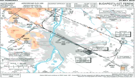
Figure 10
The start of the Final Approach Segment Instrument RNAV Data for BUD airport 13L. Source: https://ais.
hungarocontrol.hu/aip/2018-05-24/2018-05-24-AIRAC/graphics/eAIP/LH_AD_2_LHBP_ILS_OR_LOC_13L_en.pdf (23. 04. 2020.)
Finally, as shown in Figure 11 below, the final approach fix (FAF) started to be used in the final segment, extended to the 13R Runway’s Touch Height (TCH) point called MAPT, which is supposed to be 200 ft. above the runaway threshold point as per CAT I performance in IFR flights. The direction of landing is 128 degrees, almost 130 degrees, the slope between the two point from the IF WP to the RWY13 R/L would be 3 degrees. In this final segment, the use of ILS or GLS is linked to the availability of integrity, accuracy and continuity of the system, especially in bad weather or night flights. From this, the GLS system performance was approved to be better than the ILS systems.
Figure 11
The Final Approach Segment Instrument RNAV Data for BUD airport 13L. Source: https://ais.hungarocontrol.hu/
aip/2018-05-24/2018-05-24-AIRAC/graphics/eAIP/LH_AD_2_LHBP_RNAV_13R_en.pdf (23. 04. 2020.)
5. Conclusions and Recommendations
In conclusion, according to the analysis done on the availability of the GIS aiding maps for the Terminal and Final Approach modes of flights in BUD airport, using the GLS system is feasible and more accurate, not even in CAT I performance, but also in CAT II as well. This feasibility leads to the chance of more investment in installing a GBAS Landing System (GLS) station in Budapest international Airport (BUD), for the sake of having more accurate approaches and enhanced capacity of its air traffic management. Furthermore, it can be recommended that those GLS systems can be applied in military airports for night flights as well. However, the final recommendation would be – as many civil aviation authorities adopted – an alternative usage of the GLS system side by side with the existing ILS system, in order to make easier the gradual transition to the potentially coming GLS systems. As it can be seen and proved, many benefits can be achieved in terms of cost effectiveness, capacity increase, and enhanced performance.
Bibliography
‘Airport Information / Visual Approach Chart.’ Hungary Airport. Available: www.hungaryairport.
hu/airport_data.php?id=6 (23. 04. 2020.)
Alhosban, A.: ‘Electronic Warfare in NAVWAR: Impact of Electronic Attacks on GNSS/GBAS Approach Service Types C and D Landing systems and their proposed Electronic Protection Measures (EPM).’ Hadmérnök 14, no 2 (2019), 238–255. Available: https://folyoirat.
ludovika.hu/index.php/hadmernok/article/view/351/54 (09. 11. 2020.)
Alhosban, A.: ‘Impact of Multipath Error On the availability of Integrity In GBAS Application.’
Presentation at ICG Expert meetings’ proceedings, 2015, Vienna, Austria, Available: http://
www.unoosa.org/pdf/icg/2015/presentations/19.pdf (03. 05. 2020.)
Campbell, J. – Shin, M.: Essentials of Geographic Information System. Saylor Foundation, 2011.
Dautermann,T. – Felux, M. – Grosch, A.: ‘Approach service type D evaluation of the DLR GBAS testbed.’ GPS Solution 16 2012, 375–387. DOI: https://doi.org/10.1007/s10291-011-0239-3 Dautermann, T. – Ludwig, T. – Geister, R. – Ehmke, L.: ‘Extending access to localizer performance with vertical guidance approaches by means of an SBAS to GBAS converter.’ GPS Solution 24 (2020), Article No. 37. DOI: https://doi.org/10.1007/s10291-019-0947-7
‘GBAS installations.’ Google Maps. Available: www.google.com/maps/d/viewer?mid=14gN6Io- wjgVLlkjwgKKIUyjz6OXQ&ll=2.874751533561095%2C0.6307027981077908&z=2 (04. 05. 2020.)
‘Geographic Information Systems for Today and Beyond.’ Saylor.org. Available: https://
saylordotorg.github.io/text_essentials-of-geographic-information-systems/s05-03- geographic-information-systems.html (09. 11. 2020.)
Jeong, M. – Bae, J. – Jun, H. – Lee, Y.: ‘Flight test evaluation of ILS and GBAS performance at Gimpo International Airport.’ GPS Solution 20 (2016), 473–483. DOI: https://doi.
org/10.1007/s10291-015-0457-1
‘Minimum Aviation System Performance Standards for The Local Area Augmentation System (LAAS)/ RTCA DO-245A.’ RTCA 2004, p. 113. Available: https://my.rtca.org/
NC__Product?id=a1B36000001IcjtEAC (Purchased on 30. 04. 2020.)
‘Modernizing Nautical Chart Production: Next-Generation Charting System Based on Commercial Off-the-Shelf Solution.’ In: GIS Use in Map, Chart and Data Production.
ESRI. Available: www.esri.com/content/dam/esrisites/sitecore-archive/Files/Pdfs/library/
brochures/pdfs/gis-use-in-map-chart.pdf (18. 04. 2020.)
Nagle, Jim: ‘Global Air Navigation System Performance Based eANP Framework.’ SIP/WP/10 eANP Framework. Presentation at the Workshop on the Development of National Performance Framework (Lima, 13–17 April 2009). Available: www.icao.int/SAM/
Documents/2009/SIPATM2009/SIP2009ATMWP10.pdf (25. 04. 2020.)