Simulation Based Verification of the Applicability of a Novel Branch of
Computational Cybernetics in the Adaptive Control of Imperfectly Modeled Physical
Systems of Asymmetric Delay Time and Strong Non-linearities
József K. Tar, Imre J. Rudas, János F. Bitó
Budapest Polytechnic, John von Neumann Faculty of Informatics, Centre of Robotics and Automation, 1081 Budapest, Népszínház utca 8.
E-mail: tar@nik.bmf.hu, rudas@bmf.hu, bito@nik.bmf.hu Abstract:
In this paper the applicability of an adaptive control based on a novel branch of Computational Cybernetics is illustrated for two different, imperfectly and inaccurately modeled particular physical sytems. One of them is a water tank stirring cold and hot water as input and releasing the mixture through a long pipe.
The mass flow rate and the temperature are prescribed at the free end of the exit pipe while the taps at the input side can diretly be controlled. Due to the incompressibility of the fluid the variation of the mass flow rate of the output is immediately observableat the pipe’s end and is related to the control action at the input taps, while its effect on the temperature becomes measurable at the free end of the pipe only after a delay time needed for the fluid to flow through the pipe.
This results in asymmetric and non-constant delay time. The other paradigm is the thermal decay of the molecular nitrogen during a throttling down process. As is well known chemical reactions hav very drastic non-linearities and it is not easy to construct their “exact” or satisfacorily avccurate model. The fundamental principles of this new branch of Computational Cybernetics are briefly presented in the paper. To some extent it is similar to the traditional Soft Computing, but by using a priori known, uniform, lucid structure of reduced size, it can evade the enormous structures so characteristic to the usual approach. Clumsy deterministic, semi-stochastic or stochastic machine learning is replaced by simple, short, explicit algebraic procedures especially fit to real time applications.
The costs of these advantages may manifest themselves in the expected limitation of the applicabilityof this new approach. However, the simulation results exemplify the applicability of the new method in the control of systems of strong non-linearities and asymmetric delay time.
1 Introduction
A new approach for the adaptive control of imprecisely known dynamic systems under unmodeled dynamic interaction with their environment was initiated in [1].
In the family of the adaptive control methods this new one lays between the linear PID/ST and the parameter identification approaches.
Instead of the supposed analytical model's parameters the control is tuned as in the PID/ST, but it offers the possibility of using several parameters of some abstract Lie groups fit to the needs of the „non-linear control”. In the same time these parameters may be considered as that of the system model's, though they are not the part of its detailed analytical description. This „non-analytical modeling” is akin to the Soft Computing philosophy.
In this approach adaptivity means that instead of the simultaneous tuning of numerous parameters, a fast algorithm finding some linear transformation to map a very primitive initial model based expected system-behavior to the observed one is used. The so obtained „amended model” is step by step updated to trace changes by repeating this corrective mapping in each control cycle. Since no any effort is exerted to identify the possible reasons of the difference between the expected and the observed system response, it is referred to as the idea of "Situation-Dependent Partial System Identification". This anticipates the possibility for real-time applications.
Regarding the appropriate linear transformations several possibilities were investigated and successfully applied. E.g. the „Generalized Lorentz Group” [2], the „Stretched Orthogonal Group”, the “Partially Stretched Orthogonal Transformations” [3], and a special family of the „Symplectic Transformations”
[4] can be mentioned.
The key element of the new approach is the formal use of the „Modified Renormalization Transformation”. The „original” transformation was widely used e.g. by Feigenbaum in the seventies to investigate the properties of chaos [5-7]. Its useful property from our special point of view is that this (originally scalar) transformation modifies the solution of an x=f(x) fixed-point problem, since the adaptive control was formulated as a fixed-point problem, too [8]. The modification of the original transformation was necessary due to phenomenological reasons. Satisfactory conditions of the complete stability of the so obtained control for Multiple Input-Multiple Output (MIMO) systems were also highlighted in [8] by the means of perturbation calculation. This means the most rigorous limitation regarding the circle of possible application of the new method.
To release this restriction to some extent “ancillary” but simple interpolation techniques and application of “dummy parameters” were also introduced in [8].
The applicability of the method was investigated for electro-mechanical and hydrodynamic systems via simulation [9-10]. These systems were exempt of any
kind of delay or lag. In this paper a quite simple but lucid typical non-linear paradigm, a water tank of open outlet is chosen to be the subject of the new type adaptive controller. It contains continuous non-linearities due to the velocity- dependent resistance of the pipelines, saturated (bounded) non-linearities set by the temperature of the „warm” and the „cold” input water to be mixed in the tank, and the open input of the tank making it impossible for the fluid to flow back in the input pipes. Further non-linear limitation is that the velocity of the flow leaving the tank is unique function of the density and full mass of the fluid exiting the tank, so it cannot be directly controlled: only the mass flow rate of the cold and warm input is controllable. Furthermore, since the mass flow rate and the temperature of the required output is defined and measured only at the end of the pipe serving as the outlet, while the input is directly controllable at the location of the tank, the temperature signal contains considerable lag. (Due to the incompressibility of the liquid the velocity signal of the flow doesn’t suffer from considerable delay.)
In the sequel at first the basic principles of the adaptive control are described, then the models and the simulation results for the particular paradigms considered are given. Following the presentation of the typical simulation results the conclusions are drawn.
2 The basic principles of the adaptive control
From purely mathematical point of view the control task can be formulated as follows. There is given some imperfect model of the system on the basis of which some excitation is calculated to obtain a desired system response id as e=ϕ(id). The system has its inverse dynamics described by the unknown function ir=ψ(ϕ(id))=f(id) and resulting in a realized response ir instead of the desired one, id. Normally one can obtain information via observation only on the function f() considerably varying in time, and no any possibility exists for directly
"manipulaing" the nature of this function: only id as the input of f() can be
“deformed” to id* to achieve and maintain the id=f(id*) state. [Only the model function ϕ() can directly be manipulated.] On the basis of the modification of the method of renormalization widely applied in Physics the following "scaling iteration" was suggested for finding the proper deformation:
( ) ( )
I S
i S i
i i f S i S i i i f S
i0 0 0 0 0
⎯
⎯ →
⎯
=
=
=
=
∞
→ +
+
− n n n n
n
n 1 1
1 n 1 1 1
;
; ;
...
; ;
; (1)
in which the Sn matrices denote some linear transformations to be specified later.
As it can be seen these matrices maps the observed response to the desired one, and the construction of each matrix corresponds to a step in the adaptive control. It is evident that if this series converges to the identity operator just the proper
deformation is approached, therefore the controller „learns” the behavior of the observed system by step-by-step amendment and maintenance of the initial model.
(The response arrays may contain a „dummy”, that is physically not interpreted dimension of constant value, in order to evade the occurrence of the mathematically dubious 0→0, 0→finite, finite→0 cases.)
Since (1) does not unambiguously determine the possibly applicable quadratic matrices, we have additional freedom in choosing appropriate ones. The most important points are fast and efficient computation, and the ability for remaining as close to the identity transformation as possible. In the present paper an orthogonal transformation is created which transforms the realized vector into a vector parallel with the desired one while leaves the orthogonal sub-space of these two vectors unchanged. Then proper stretching/shrinking factor is calculated which makes the absolute value of the realized vector equal to that of the desired one. On this basis two linear operators are created which apply the appropriate stretches/shrinks in the “realized” one-dimensional sub-spaces, rotate them to be parallel to the “desired” directions, and leave the orthogonal sub-spaces unchanged [3]. This operation evidently equals to the identity operator if the desired response just is equal to the desired one, and remains in the close vicinity of the unit matrix if the non-zero desired and realized responses are very close to each other. In the application of the above method it was implicitly supposed that practically the „desired” and the „observed” responses were simultaneously observable/available.
3 Description of the water tank
The water tank considered is an open vessel into which hot and cold water of fixed temperatures T1=10 °C, and T2=90 °C is purred from the top. The mass flow rates of the input components M1,M2 [kg/s] are directly controllable via electric valves. According to [11] the density of the water in the above temperature range is 999.7 kg/m3 within 3.4 % precision, so it is approximated with the mean value over this interval as ρ=982.48 kg/m3 as a constant. The cross-sectional area of the tank is A=1 m2, and it is supposed to be high enough to contain all the amount of the liquid occurring in the calculations. At the bottom level of the tank a pipe of diameter D=1.8×10⁻¹ m, length L=10 m, and relative internal surface roughness of krel=1.5×10⁻² is attached. The pressure increase with respect to the environmental pressure, that is the actual pressure difference driving the water flow in the pipe is Δp=M(t)g/A Pa if g=9.87 m/s2 is the gravitational acceleration, and M(t) in kg units denotes the actual mass of the fluid in the tank. By neglecting the minor pressure losses at the exit at the tank and the free end of the pipe, the velocity of the flow in the pipe, u is determined by the equation
⎟⎟⎠
⎜⎜ ⎞
⎝
= ⎛
×
⎟ Δ
⎠
⎜ ⎞
⎝
⎛
krel
f uD u p L
D ,
5 . 0
4 2 μ
ρ
ρ (2)
in which f is the non-dimensional friction factor, and μ denotes the dynamic viscosity of the fluid. The viscosity mainly depends on the fluid temperature, and in the given range it varies within the range of [3.11×10⁻⁴, 1.3×10⁻³] kg/(m×s). The non-dimensional expression Re:=ρuD/μ defines the Reynolds Number. The f(Re,krel) function is given in the well-known Moody Diagram [12]. At the given numerical value of krel f practically is constant (1.21×10⁻²) if Re is greater than 10-5. Allowing Mmin=100 kg minimum mass of water in the tank and supposing that f=1.21×10⁻² (1) yields the minimum seeped of water flow as umin=0.86 m/s to which the Re≅1.16×10⁵ values belongs if the maximum value of the viscosity in the given range is taken into account. Therefore, if the mass of the fluid in the tank remains over 100 kg, the flow in the pipe will be fully turbulent with a constant f=1.21×10⁻² friction factor. For the given pipe length a delay time of about a few seconds can be expected for the temperature signal.
Regarding the mixing of the cold and warm water, the heat capacity of the fluid mainly depends on the temperature and varies in the interval [4.193, 4.208]
kJ/(kg×°K), that is it can also be considered to be constant.
Under the above conditions the operation of the tank can be approximated by the following differential equations:
2 2 1
1 M
M T M T
M T
T T −
− +
= (3)
D K L AKf
gM
M D 2 , 4
4
2
3= =
ρ ρ
π (4)
in which T denotes the temperature of the mixed fluid in the tank, and M3 means the mass flow rate at the output. While T can directly be controlled by the valves at the input, the output mass flow rate cannot. This gives the system a kind of
„inertia”. Only the time-derivative of the output mass flow rate can be directly controlled due to the conservation of the mass of the fluid as
AKfMM g
M D
4 2 4
2 3
ρ
=π (5)
3 2
1 M M
M
M = + − (6)
For the directly controllable quantities therefore the following pair of equations is obtained:
( )
AKf g M D
AKfM M g M D
M M T M T
M T T T
2 32 2
8
4 2 2 1 2
3
2 2 1 1
π ρ
π + −
=
+ −
= −
(7)
in the integration of which (4) and (6) can also be used. Regarding the problem of the delay of observation, the quantities in (4-7) are to be taken in common time instant if they are measured/observed immediately at the tank. However, if the temperature is measured at the outlet of the pipe, one has to distinguish between the actual values in the tank and in the outlet. It can be stated, that if t is the time of the observation, and the input valves are controlled by fast electronic signals, than
( )
t T(
t( )
t)
TObs = Tank −δ (8)
n which the lag δ(t) is determined by the equation
( )
( )
−
∫
= t
t t
d u L
δ
τ
τ (9)
Due to the incompressibility of the liquid and the fast electric signals the mass flow rates are immediately observable and no such distinction has to be done.Principles of the adaptive control
However, in the case of the present paradigm the effect of the control action immediately can be observed on the output mass flow rate, but its observation suffers from a lag δ(t) as far as temperature is concerned. This „asymmetry” is tackled in the control in the following way. If a P-type controller is applied, an exponentially asymptotic trajectory reproduction is prescribed by defining certain
„desired” time-derivatives in the following manner:
( ) ( ) ( )
( ) ( ) ( )
( ) ( )
⎥⎦⎢ ⎤
⎣
⎡
− + −
⎥⎦
⎢ ⎤
⎣
=⎡
⎥⎦
⎢ ⎤
⎣
⎡
t T t T
t M t M t
T t M t T
t M
R N
R N
N N
D D
3 3
3
3
α (10)
where the indices D, N, and R refer to the „desired”, „nominal”, and the „realized”
(actual) values, and α controls the speed of the desired error-relaxation. In the adaptive version, in the lack of any time lag, the matrices in (10) were constructed from the pair
( ) ( ) ( ) ( )
⎥⎥
⎥
⎦
⎤
⎢⎢
⎢
⎣
⎡
=
⎥⎥
⎥
⎦
⎤
⎢⎢
⎢
⎣
⎡
C t T
t M C
t T
t M
D D
R R
3 3
S (11)
where C denotes the „dummy” parameter introduced due to pure technical reasons only. In the „asymmetric” case, if t measures the time at the outlet of the pipe the error term fed back in (11) can be replaced by
( ) ( )
( )
( ) ( ( ) )
⎥⎦⎢ ⎤
⎣
⎡
−
−
−
−
t t T t t T
t M t M
R N
R N
δ δ
3
3
(12)
expressing the fact that the actual response observable at the end of the pipe at time „t” can be related to a control action based on a desired derivative computed previously at t-δ(t), since the observed values at t correspond to the available
„freshest” information on that control action. On the same basis, the S matrices of the adaptive law at time t are calculated from the pair of vectors
( ) ( ) ( ) [ ( ) ( ) ]
( ) [ ( ) ( ) ]
⎥⎥
⎥
⎦
⎤
⎢⎢
⎢
⎣
⎡
−
−
− +
−
− +
⎥⎥
⎥
⎦
⎤
⎢⎢
⎢
⎣
⎡
C
t T t T t
T
t M t M t M C
t T
t M
R N
N
R N
N
R R
δ δ
α δ
α
3 3 3 3
, (13)
In similar way, if instead of a P-type a PI-type control becomes necessary to calculate the desired derivatives in the linear control approach, it is reasonable to compute the integrated error with the same delay as above, and the adaptive matrices have to be computed from the so obtained counterpart of (12).
Since amongst the conditions for which the convergence of the method was proved near-identity transformations were supposed in the perturbation theory, a parameter ξ measuring the „extent of the necessary transformation”, a „shape factor” s, and a „regulation factor” λ can be introduced in a linear interpolation with small positive ε1, ε2 values as
( )
i f(
i f)
i f
i
f = + −
− +
− + +
− =
= 1 2 1 , ˆd d
1 1 1
), ,
: max( λ
ξ ε ξ ε ε λ
ξ s
s
d d
(14) This interpolation reduces the task of the adaptive control in the more critical session and helps to keep the necessary linear transformation in the vicinity of the identity operator.
4 Simulation results for the water tank
In the simulations the non-adaptive and the adaptive controls’ results are compared to each other α=0.25 1/s proportional, and β=10-3×α s-2, that is with a very small integrating coefficient in Fig. 1. As a rough system model, as an analogy of (6), constant coefficients a, b, c, and d were used as
( M M ) d
c M M b M a
T =
1+
2,
3=
1+
2−
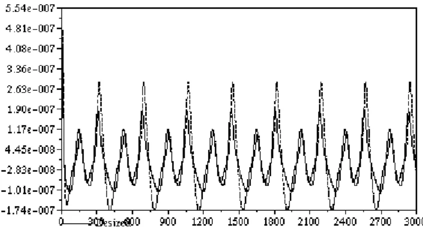
.Figure 1. The operation of the simple PID (left column) and the adaptive (right column): prescribed and simulated mass flow rate [kg/s], prescribed and simulated temperature [°C], and the angle of the necessary step-by-step abtsract rotation (for
the non-adaptive version it is calculated only without being used) vs. time [s]
In Fig. 2 the mass flow rate and temperature tracking error, the delaya time, and the regulating factor λ are given for the adaptive controller to reveal some details.
It can be seen that adaptivity causes considerable amendment in the accuracy of the control.
5 Thermal decay of the molecular nitrogen
The simplest examples of the chemical reactions are the reactions taking place in the mixtures of ideal gases. The thermodynamic model of these gases can be reconstructed by the use of certain “basic data” belonging to the temperture dependence of the equilibrium constant, the stoichiometric coefficients of the Figure 2. The tracking error for the mass flow rate [kg/s] and the temperature [°C],
the time delay [s], and the regulating factor λ of the adaptive controller vs. time [s].
reaction and the chemical potential of the appropriate components in the mixture.
If the chemical reaction is written in the form using positive or negative rational stoichiometric coefficients νi and symbolic notations for the components Ai as
∑ ⇔
i i
i
A 0
ν
, (15)and the model of the components is built up from the temperature-dependence of the molar heat of the gas cv(T) at constant volume by using the functions
( ) ( )
∫
−
−
= Ψ
T
T vi i
i
dt
t t c R R T s
T
0
ˆ 1 1
;
0 0 (16)(R denotes the universal gas constant, T denotes the actual temperature in [°K]
units, and T0 is an arbitrary positive starting point of integration), the internal energy and the entropy of the mixture take the form as
{ }
( ) ∑ ∫ ( ) ⎥ ⎥
⎦
⎤
⎢ ⎢
⎣
⎡ ⎟
⎠
⎜ ⎞
⎝
− ⎛ Ψ
=
i
T
T i i
i
dt
dt t t d R N
N V T E
0
ˆ
0,
, ε
(17){ }
( ) ∑ ( )
⎥⎦
⎢ ⎤
⎣
⎡ Ψ +
=
i i
i
i N
R V T T R-R N N
V T
S , , ; 0 ln . (18)
It can clearly be seen that
ε
0i, s
0i denote the molar internal energy and entropy of the components at temperature T0. The pair of equations (16) and (17) makes it possible to deduce all the thermal data of the mixture. Via applying the 2nd Postulate of Thermodynamics for the thermal equilibrium of the mixture we obtain the socalled “Mass Action Law” stating that the exclusively temperature- dependent “equilibrium constant” K(T) and the full pressure of the system p imposes a restriction to the possible chemical composition of the mixture.( ) = ∑ ∏ ⎜ ⎝ ⎛ ⎟ ⎠ ⎞ = ∑
i i i
i
N N
N p N
T K
i i
i
,
ν ν
(19) On one hand, by measuring the temperature, the pressure, and the chemical
composition of the mixture validity of (19) can be verifyed and K(T) can be tabulated. On the other hand it is related to the model of the mixture in the following form:
[ ln ( ) ] + ∑ ( ln + 1 )
−
∑ = dT d T K T RT
i i
i i
i
ψ ν
ν
(20)The chemical potential of the “pure” components just are equal to their molar Gibbs potential also related to the model. By the use of tabulated data describing the molar Gibbs potential of certain components the individual model functions of these components can be found as, e.g. for the molecular nitrogen as
( ) ( )
1 1 ln
, 1 ,
; 2
2 0 + +
∂
= ∂
Ψ p
RT T
p T T R
T N
N
μ
(21)If our mixture consists of atomic and molecular nitrogen only (20) and (21) togeher determines ψN, too, for the atomic nitrogen. Since the entropy constants are built in in the ψ functions, and for since for the internal energy constants the relation
∑ ∫ ( )
∑ ⎟ ⎟
⎠
⎞
⎜ ⎜
⎝
⎛ Ψ −
+ Ψ
−
−
=
i
T
T i i
i i
i
i
dt RT RT
dt t d R RT T
K
RT ln ( ) ln
ˆ
0
0
ν
ε
ν
(22)can be deduced, too, the energy constants of the atomic nitrogen can also be computed rom that of the molecular one.
Whenever a well defined amount of mixture of N and N2 gases is in thermal equilibrium at a given temperature and pressure is throttled down to a prescribed pressure p, its full enthalpy H(T,p,NN2,NN), and its full mass M(NN2,NN) is conserved, furthermore the mixture has to satisfy the Mass Action Law at this lower pressure p. These three equations determine the new value of T, NN2, and NN
at this lower pressure. Via applying various numerical fitting techniques no xN vs p
0,0000E+00 5,0000E-06 1,0000E-05 1,5000E-05 2,0000E-05 2,5000E-05
0 0,0002 0,0004 0,0006 0,0008 0,001 Pa
nondimensional
xN Poly. (xN)
Figure 3. The mole fraction of the atomic nitrogen [non-diemnsional]
during the process of throttlin down at low pressure [Pa] and high temperature
detailed here, by the use of the MICROSOFT EXCEL’s SOLVER a third order polynomial was fitted to the xN(p) mole fraction of the atomic component of the mixture. The result is illustrated in Fig. 3.
6 Adaptive control of the thermal decay
In this case the controller’s task is to giarantee an appropriate p(t) function to produce a gas of nominal xNN(t) composition. For this purpose the time derivative of the p(t) function can directly be controlled. As a rough system model a constant value serving as the estimation of the
∂ x
N∂ p
derivative is used. Being a SISO system, for the control of this reaction scalar multiplication factors are used in the following form:( ) ( ) ( )
⎪ ⎩
⎪ ⎨
⎧ ≠ ≠
+
× +
=
otherwise
x and x
if x
x x sign x
n sign s
R Des
R Des R Des
1
0
: 0
ε
ε
(23)
in which ε is a very small number of about 10-25 order of magnitude to avoid both division and multiplication by zero in the control algorithm.
In Fig. 4 the nominal and simulated mole fraction values are described for the the non-adaptive and the adaptive approach, while Fig. 5 describes the tracking error in more details. It is evident that the adaptive completion of the control significantly increases the quality of the control.
To reveal details in Fig. 6 describes the desired and simulated speed of change in the pressure for the non-adaptive and the adaptive control. The differences are quite significant in the non-adaptive case.
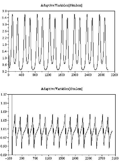
Finally, in Fig. 7 the variation of the adaptive parameter (the scalar s(n) multiplication factors) are described for the non-adaptive [not used but calculated only] and the adaptive cases. It is evident that the consecutive corrections of the adaptive control are very close to 1, while the similar graph pertaining to the non- adaptive case conveys information on the modeling errors and inaccuracies.
5 Conclusions
In this paper the behavior of the conventional PID and that of an adaptive control based on a novel branch of Computational Cybernetics were compared to each
other in the case of controlling an approximately modeled non-linear system having considerable and non-constant delay time.
The simulation results made it clear that a simple increase in the integrating coefficient can cause considerable improvement in the control but cannot approach the accuracy of the adaptive control when the delay time is important.
The here presented approach evades the sizing and learning problems having central significance in the rather traditional branch of soft computing [e.g. 14-20]
by applying simple uniform operations in finite number of algebraic steps. The Figure 4. The nominal and the simulated mole fraction of atomic nitrogen in
the non-adaptive and the adaptive case
size of the vectors and matrices used by it is simply determined by the modeled number of the degree of freedom of the system to be controlled. The “costs” of these advantages appear in the relatively limited class of problems for which the novel method can be applied.
The critical point is the proper convergence of the series of the linear transformations.
However the here-investigated paradigms suggests that from practical point of view the class of problems for which the new approach can be applied may be quite wide and may have drastic non-linearities, and time lag, too.
Figure 5. The tracking error of the non-adaptive and the adaptive control Figure 5. The tracking error of the non-adaptive and the adaptive control
Figure 6. The desired and simulated speed of change in the pressure for the non-adaptive and the adaptive control
5 Acknowledgment
The authors gratefully acknowledge the support by the Hungarian National Research Fund (OTKA T034651, T034212 projects).
Figure 7. The adaptive variable in the case of the non-adaptive and the adaptive control (calculated only but not used in the non-adaptive case)
6 References
[1] M. Bröcker, M. Lemmen: "Nonlinear Control Methods for Disturbance Rejection on a Hydraulically Driven Flexible Robot", in the Proc. of the Second International Workshop On Robot Motion And Control, RoMoCo'01, October 18-20, 2001, Bukowy Dworek, Poland, pp. 213-217, ISBN: 83-7143-515-0, IEEE catalog Number:
01EX535.
[1] J. K. Tar, I. J. Rudas, J. F. Bitó: "Group Theoretical Approach in Using Canonical Transformations and Symplectic Geometry in the Control of Approximately Modeled Mechanical Systems Interacting with Unmodelled Environment", Robotica, Vol. 15, pp. 163-179, 1997.
[2] J. K. Tar, I. J. Rudas, J. F. Bitó, K. Jezernik: "A Generalized Lorentz Group-Based Adaptive Control for DC Drives Driving Mechanical Components", in the Proc. of The 10th International Conference on Advanced Robotics 2001 (ICAR 2001), August 22-25, 2001, Hotel Mercure Buda, Budapest, Hungary, pp. 299-305 (ISBN: 963 7154 05 1).
[3] Yahya El Hini: "Comparison of the Application of the Symplectic and the Partially Stretched Orthogonal Transformations in a New Branch of Adaptive Control for Mechanical Devices", Proc. of the 10th International Conference on Advanced Robotics", August 22-25, Budapest, Hungary, pp. 701-706, ISBN 963 7154 05 1.
[4] J. K. Tar, A. Bencsik, J. F. Bitó, K. Jezernik: “Application of a New Family of Symplectic Transformations in the Adaptive Control of Mechanical Systems”, in the Proc. of the 2002 28th Annual Conference of the IEEE Industrial Electronics Society, Nov. 5-8 2002 Sevilla, Spain, Paper SF-001810, CD issue, ISBN 0-7803-7475-4, IEEE Catalog Number: 02CH37363C.
[5] M.J. Feigenbaum, J. Stat. Phys. 19, 25, 1978;
[6] M.J. Feigenbaum, J. Stat. Phys. 21, 669, 1979;
[7] M.J. Feigenbaum, Commun. Math. Phys. 77, 65, 1980;
[8] J. K. Tar, J. F. Bitó, K. Kozłowski, B. Pátkai, D. Tikk: "Convergence Properties of the Modified Renormalization Algorithm Based Adaptive Control Supported by Ancillary Methods", Proc. of the 3rd International Workshop on Robot Motion and Control (ROMOCO ’02), Bukowy Dworek, Poland, 9-11 November, 2002, pp. 51-56, ISBN 83-7143-429-4, IEEE Catalog Number: 02EX616.
[9] J. K. Tar, I. J. Rudas, J. F. Bitó, L. Horváth, K. Kozłowski: ”Analysis of the Effect of Backlash and Joint Acceleration Measurement Noise in the Adaptive Control of Electro-mechanical Systems”, Accepted for publication on the 2003 IEEE International Symposium on Industrial Electronics (ISIE 2003), June 9-12, 2003, Rio de Janeiro, Brasil, CD issue, file BF-000965.pdf, ISBN 0-7803-7912-8, IEEE Catalog Number: 03th8692.
[10] J. F. Bitó, J. K. Tar, I. J. Rudas: “Novel Adaptive Control of Mechanical Systems Driven by Electromechanical Hydraulic Drives”, in the Proc. of the 5th IFIP International Conference on Information Technology for BALANCED AUTOMATION SYSTEMS In Manufacturing and Services, Sheraton Towers and Resort Hotel, Cancún, Mexico September 25-27, 2002, Cancún, Mexico.
[11] G. F. C. Rogers, Y. R. Mayhew: „Thermodynamic and Transport Properties of Fluids – SI Units”, 4th Edition, Blackwell Oxford UK & Cambridge USA, 1980, ISBN 0- 631-90265-1.
[12] B. S. Massey: „Mechanics of Fluids”, Sixth Edition, Chapman & Hall, 1989, ISBN 0 412 34280 4.
[13] Dr. Harmatha András: “Termodinamika műszakiaknak”, (in Hungarian), Műszaki Könyvkiadó, Budapest, 1982, ISBN 963 10 4467 X, p. 197 and 276.
[14] R. Reed: "Pruning Algorithms - A Survey", IEEE Transactions on Neural Networks, 4., pp.- 740-747, 1993.
[15] S. Fahlmann, C. Lebiere: "The Cascade-Correlation Learning Architecture", Advances in Neural Information Processing Systems, 2, pp. 524-532, 1990.
[16] T. Nabhan, A. Zomaya: "Toward Generating Neural Network Structures for Function Approximation", Neural Networks, 7, pp. 89-9, 1994.
[17] G. Magoulas, N. Vrahatis, G. Androulakis: "Effective Backpropagation Training with Variable Stepsize" Neural Networks, 10, pp. 69-82, 1997.
[18] C. Chen, W. Chang: "A Feedforward Neural Network with Function Shape Autotuning", Neural Networks, 9, pp. 627-641, 1996.
[19] W. Kinnenbrock: "Accelerating the Standard Backpropagation Method Using a Genetic Approach", Neurocomputing, 6, pp. 583-588, 1994.
[20] A. Kanarachos, K. Geramanis: "Semi-Stochastic Complex Neural Networks", IFAC- CAEA '98 Control Applications and Ergonomics in Agriculture, pp. 47-52, 1998.
![Figure 1. The operation of the simple PID (left column) and the adaptive (right column): prescribed and simulated mass flow rate [kg/s], prescribed and simulated temperature [°C], and the angle of the necessary step-by-step abtsract rotation (for](https://thumb-eu.123doks.com/thumbv2/9dokorg/1231878.94471/8.892.210.665.240.917/operation-adaptive-prescribed-simulated-prescribed-simulated-temperature-necessary.webp)
![Figure 3. The mole fraction of the atomic nitrogen [non-diemnsional]](https://thumb-eu.123doks.com/thumbv2/9dokorg/1231878.94471/11.892.227.665.266.515/figure-mole-fraction-atomic-nitrogen-non-diemnsional.webp)