Application Benchmark of Three Micro Hole Machining Processes for Manufacturing the Nozzle of a Medical Water Jet Machine
Vilmos Csala, Tibor Szalay, Balázs Farkas, Sándor Markos
Department of Manufacturing Science and Engineering, Budapest University of Technology and Economics, Műegyetem rkp. 3, H-1111 Budapest, Hungary, csala@manuf.bme.hu, szalay@manuf.bme.hu, farkasb@manuf.bme.hu, markos@manuf.bme.hu
Abstract: Micro hole machining refers to the process of drilling holes with a diameter of less than 1 millimeter. This paper compares three commonly used technologies:
mechanical drilling, laser machining and electrical discharge machining. All of these techniques were analyzed based on an experimental measurement of dimensional accuracy, circularity, burr formation and the image of the internal surface. The most significant criterion of analysis is surface quality, as the main purpose of the examination was to find the most precise process. In addition, a detailed cost analysis, pertaining to machining time, the tools and machines was performed. The experiment utilized a high precision lathe, an Nd:YAG laser and an electrical discharge machine. The final results revealed the micro drilling process as the one with the most promising parameters. Therefore, it was suggested for industrial applications. However, once the economic factors were not taken into account, the EDM also became a more attractive option, based on good technical and quality parameters.
Keywords: micro manufacturing; drilling; EDM; laser machining
1 Introduction
Nowadays, the machining of micro holes is in high demand, when it comes to industrial applications. Although there are numerous challenges and difficulties related to such technologies, machining holes with a diameter of less than 1 millimeter or even 100 µm is considered to be common practice in medical device production, in the automotive industry and in other state of the art technologies.
Additionally, manufacturing miniature parts or features, have a tradition and several technologies are known that can successfully accomplish the task, such as, laser machining or EDM. The most important difference in today’s production practice, is that we need to manufacture a high volume of these parts, and we also need to retain this ability in the serial production. Fortunately, more and more
companies provide this technology, resulting in a rapid development of micro- scale parts machining. [1, 2]
Figure 1 Taniguchi’s prognosis [4]
According to Taniguchi’s prediction, machining parts and details in the micron range, using traditional cutting operations will become available at the beginning of the 21st Century [3]. (Figure 1) The curves in Figure 1, display the manufacturing capability of the available technologies as a function of achievable accuracy, dating as far back as 1940. As Taniguchi describes in the figure, the size of the micro machining end product is around 100 µm. Table 1 summarizes the most frequently used machining operations as well as the minimum sizes that can be produced by using them.
Table 1
Size limit of technologies [1]
Machining operation Achievable size
Micro-molding 500 µm
Micro-pressing 50 µm
Micro-milling and grinding 25 µm
Stereolitography 12 µm
Micro-EDM 5 µm
Ion-beam machining 0.2 µm
Our motivation to compare the most frequently used micro-hole machining operations by experimental means originated from our strong interest in a company dealing with the production of medical devices. This particular firm has
developed medical water jet machining devices for surgical applications. The general structure of the machining device can be observed in Figure 2. Medical devices need to conform to some extreme requirements. First of all, the device must be controlled with high precision; moreover, both the cutting fluid and the material of the nozzle must be bio-compatible. In medical water jet machining, saline is the most commonly used working fluid, while the nozzle is usually made of metal or metal alloys, such as alumina, titanium and platinum. In order to provide the necessary fluid velocity for cutting, the diameter of the nozzle must be between 0.1 – 0.15 mm so we created the test part that can be seen on Figure 3 [5].
Figure 2
The medical water jet machine
Our investigations were aimed at selecting a suitable technology for the medical water jet machining device’s cutting nozzle production. In the end, stainless steel was chosen as test material and experiments were carried out, where drilling was limited to electrical-discharge machining and laser machining trials. By varying the machining parameters, we measured the form and diameter accuracy, the burr formation, the hole’s surface roughness, as well as the machining time. Based on our experimental results, we made a suggestion concerning the most suitable technology.
Figure 3 The cutting nozzle
1. pedal (switching on-off the device)
2. motor/generator 3. saline
4. pump piston 5. rubber tubing 6. cutting nozzle
2 Examination of the Holes
First, it is essential to clarify the definition of relevant methods and equipment.
The microscopic images were taken by the Dino-Lite Pro AM3013T digital microscope that has a magnification factor of 500x.
Dimensional accuracy. The investigation was carried out by the microscope’s computer program called DinoCapture. After calibrating the software, the diameter of the holes was measured manually by selecting the program option that makes it possible to mark some edge points of the hole in the microscopic images.
Afterwards, the program automatically calculated its diameter.
Circularity. Precise results can be obtained by using e.g. coordinate measuring machine probes with a very small spherical tip. [6] In the absence of such a device, the measurement of the circularity was once again carried out by DinoCapture. 3-3 points have been marked within both the inner and the outer circle of the entrance and the difference between the two radiuses has yielded the circularity results. This method is merely suitable for providing an approximation of the true values as the inner and the outer circles are not concentric. However, the effect of this limitation is negligible. The circularity was graded on a scale ranging from 1 to 5 where:
1: value of the circularity ≤5 µm 2: value of the circularity ≤10 µm 3: value of the circularity ≤15 µm 4: value of the circularity ≤20 µm 5: value of the circularity ≤25 µm
Burr formation. The burr formation was examined by analyzing the microscopic images. Previous research [7] has established the basic burr types in conventional drilling. The shape of the burrs can be uniform (a)(b), crown (d) and transient (c).
The transient burr is halfway between the uniform and the crown burr. (Figure 4)
Figure 4 Drilling burr types [7]
Quality of the internal surface. In order to be able to measure the internal surface, the holes had to be cut in half. The examination of the internal surface quality was carried out by a scanning electron microscope (Philips XL 30 SEM) in a laboratory belonging to the Department of Material Science and Engineering (Figure 5).
Figure 5
Scanning Electron Microscope
It was not a goal of these experiments and measurements to investigate the machinability parameters [8,9] (e.g. energetics, tool wear or tool life) Nevertheless, the authors consider further machinability research of micro drilling to be one of the primary focus areas of their team’s activities.
3 Machining Experiments
3.1 Micro-Drilling
Although mechanical drilling is a traditional cutting technology and as such, its parameters, results as well as the overall process are investigated extensively on a macro level, the micro-drilling process has several modifying factors and we also concluded our results based on this latter approach. When it comes to micro- drilling, there are plenty of additional influencing parameters to be taken into account. These include, but are not limited to, the remarkably high spindle revolution (between 1-12 x 104 min-1), the stability of the spindle and the high cutting forces resulting from a relatively big edge radius (see Figure 6) [10, 11].
Figure 6
Elastic deformation in micro-drilling as a consequence of the low chip thickness - edge radius ratio The drilling experiments were carried out in a laboratory owned by the Department of Manufacturing Science and Technology. The machine tool was a high precision lathe called Csepel Ultraturn1. This machine tool is equipped with an additional high speed spindle with a maximum rotational speed of 60000 min-1. Table 2 shows the measured positioning capability of this machine. [12] Figure 7 depicts the machining environment of the micro-drilling experiments.
During the experiments, SECO tools, an SD22 center drill and an SD26 micro- drill were used. The appropriate tools were chosen after comparing the choice of the main producers and distributors based on the price and technology descriptions.
The experiments also required the use of ASTM 316 (EN 1.4401) stainless steel sheets, the cutting speed and the feed of which were often altered. The detailed parameters of the experiments can be found in Table 3. Figure 8 shows some of the holes corresponding to the numbers presented in the experiment plan (Table 3); the apostrophes indicate the cases where the pilot drill was broken and thus it could not be used.
Table 2
Accuracy of Csepel machine tool UP 1 lathe (Csepel Ultraturn) [mm]
Axial error of the spindle 0.001 Radial error of the spindle 0.001 Positioning unit in z direction 0.0001 Positioning unit in x direction 0.0001 Positioning accuracy 0.001
Repeatability 0.001
Figure 7
The Csepel Ultraturn machine tool
Table 3
Plan for the micro-drilling experiments Plan for the experiments No. Diameter
[mm]
Cutting speed [m/min]
revolution number
[min-1]
feed [mm/rev.]
feed rate [mm/min]
1 0.15 4.712 10000 0.001 10
2 0.15 4.712 10000 0.002 20
3 0.15 4.712 10000 0.003 30
4 0.15 9.425 20000 0.001 20
5 0.15 9.425 20000 0.002 40
6 0.15 9.425 20000 0.003 60
7 0.15 14.137 30000 0.001 30
8 0.15 14.137 30000 0.002 60
9 0.15 14.137 30000 0.003 90
Figure 8
Results of the drilling experiments
Machining time. Machining times depend on the speed and the feed. The shortest time was 8 seconds, whereas the longest was 18 seconds.
Dimensional accuracy. The diameters of the micro-holes are summarized in Table 4. The numbering of the holes in this table is in correspondence with that in Table 3 (the experiment plan).
Table 4 shows that the variation of the parameters did not have a significant influence on the results. However, there are a few exceptions; whenever the pilot drill was not used, the diameter was smaller compared to its size without the pilot drill.
Table 4 Diameter of the micro-holes
Micro-drilling
No. 316 No. 316
1 Ø0.152 mm 7 Ø0.156 mm
2 Ø0.152 mm 8 Ø0.154 mm
3 Ø0.156 mm 9 Ø0.152 mm
4 Ø0.154 mm 11’ Ø0.148 mm
5 Ø0.155 mm 12’ Ø0.148 mm
6 Ø0.158 mm 13’ Ø0.146 mm
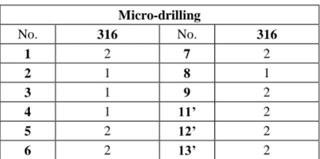
Circularity. Table 5 demonstrates that the circularity values are appropriate. They refer back to the graded scale (1 to 5) developed earlier in the paper for the purpose of categorizing the approximate circularity values. In Table 5, all the values are between 1 and 2, but we can see that without the use of the pilot drill, we got 2 as a result in each case.
Table 5 Circularity of micro-holes
Micro-drilling
No. 316 No. 316
1 2 7 2
2 1 8 1
3 1 9 2
4 1 11’ 2
5 2 12’ 2
6 2 13’ 2
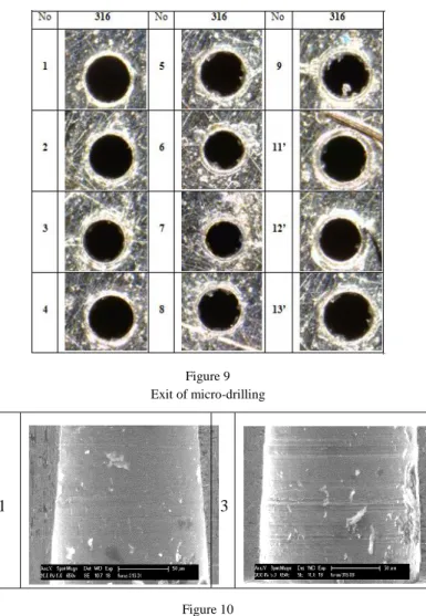
Burr formation. Figure 9 shows the exits of micro-drilling. When the cutting speed and the feed were increased, there was also a noticeable surge in burr formation, mostly resulting in the appearance of transient burrs. This time, however, the use of the pilot drill did not have an impact on the results.
Images of the internal surface. As shown in Figure 10, the surface got the most scratches when we used a minimal cutting speed combined with a maximum feed.
Increasing the feed led to further deterioration of the surface quality.
Figure 9 Exit of micro-drilling
1 3
Figure 10 SEM images of micro-drilling
3.2 Laser Drilling
The laser drilling experiments were carried out in the laboratory of the Department of Material Science and Engineering. We used the LASAG KLS 246- FC 40 Nd:YAG laser cutting machine that has an average power of 15 W with a maximum exciting frequency of 5000 Hz. Its minimal focal diameter is 0.03 mm.
Therefore it is suitable for producing a hole with a diameter of 0.15 mm. In hole machining application We used a circular trajectory cutting method in the hole machining process. The hole creation strategy can be observed in Figure 11, where the cutting starts out from the center point (1) then an inner circle is applied for roughing (2) and finally, the requested diameter is finished by creating a second circle (3). The machining environment can be seen in Figure 12.
Figure 11 Circular cutting trajectory
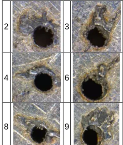
During the experiments we varied the pulse time, the frequency, the average power and energy level, as well as the pressure of the oxygen inlet. Table 6 demonstrates the plan for the laser drilling experiments. As Figure 13 reveals, the quality of the laser cutting is lower than that of the micro-drilling operation in terms of form and diameter accuracy. There are only a few holes that fall within the acceptable range of parameters.
Figure 12 Figure 13
The laser drilling environment Results of laser drilling
2 3
4 6
8 9
laser
moving table
moving axes
handling joystick
Table 6
The plan for the laser drilling experiments Plan for the experiments in laser drilling No. of
holes
Voltage [v]
Pulse time [ms]
Frequency [Hz]
Cutting speed
[m/s]
Acceler ation [m/s2]
Average power
[W]
Average energy
[mJ]
Pressure of oxygen
[bar]
1 - 3 350 0.1 500 1 0.5 15 36 4
4 - 6 350 0.1 500 1 0.5 15 36 5
7 – 9 350 0.1 500 1 0.5 15 36 6
10 – 12 350 0.05 900 1 0.5 13-14 15.3 4
13 – 15 350 0.05 900 1 0.5 13-14 15.3 5
16 - 18 350 0.05 900 1 0.5 13-14 15.3 6
The machining took around 2 seconds.
Dimensional accuracy. The diameter values of the micro holes can be found in Table 7 A). As the frequency was gradually increased, the diameters of the holes became more and more accurate. However, the pressure of the oxygen inlet did not influence the results.
Table 7
Diameter and the circularity of the micro-holes Laser-drilling
A) Diameter B) Circularity
No. 316 No. 316
3 Ø0.192 mm 3 4
6 Ø0.204 mm 6 4
9 Ø0.206 mm 9 3
12 Ø0.174 mm 12 4
14 Ø0.166 mm 14 3
18 Ø0.170 mm 18 3
Circularity. The circularity values are displayed in Table 7 B). When the power was at a high level, the pressure of the oxygen inlet did not have a particular influence on the results. However, in cases when the power was low, the frequency was high and the pressure of the oxygen inlet was increased, the overall quality of the circularity was improved. Thus, based on the values in the table, the quality of the circularity is inappropriate.
Burr formation. Figure 13 illustrates the appearance of burrs at the entrance of laser-drilled hole. The burr was generated when the laser beam slammed into the material and the material melted. A higher power level leads to similarly increased burr formation.
Images of the internal surface. Figure 14 depicts the internal surfaces. Since the material has also melted all along the internal surface, the quality level is inappropriate.
3 6
Figure 14 SEM images of laser drilling
3.3 Micro-EDM
As before, the micro electrical discharge machining experiments were carried out in a laboratory belonging to the Department of Manufacturing Science and Technology. Figure 15 shows that we used the Sarix SX100 micro EDM machine tool. The diameter of the applied electrode was Ø 0.15 mm and made of CKi08 material (Sarix regularly used this electrode material that contains 92% WC and 8% Co). During the hole drilling process, we varied the pulse time, the voltage and the frequency. The plan for the micro-EDM experiments can be seen in Table 8. The applied parameters were chosen based on previous experiences and on state of the arts research literature [13].
Figure 15 Sarix micro-EDM machine
Table 8
Plan for the micro-EDM experiments Plan for the experiment in micro-EDM No. Frequency
[Hz]
Voltage [V]
Current [A]
Pulse time [ms]
Spark-gap [µm] Gain
1 100 80 80 4 72 10
2 100 90 80 4 72 10
3 100 100 80 4 72 10
4 120 80 80 4 72 10
5 120 90 80 4 72 10
6 120 100 80 4 72 10
7 150 80 80 4 72 10
8 150 90 80 4 72 10
9 150 100 80 4 72 10
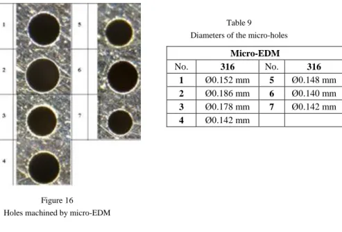
Figure 16 displays some of the results of the machining experiments. The form accuracy of the holes is comparable with that obtained by micro-drilling. In terms of cost and machining time, however, this technology is not the most efficient one.
Machining times were a subject to set discharge parameters. The shortest time was 8 minutes, while the longest lasted for 36 minutes. These times could be reduced by using optional machining parameters.
Dimensional accuracy. The diameters of the micro holes are fully appropriate.
There are two outliers (2 and 3) as shown in Table 9.
Table 9
Diameters of the micro-holes Micro-EDM
No. 316 No. 316
1 Ø0.152 mm 5 Ø0.148 mm 2 Ø0.186 mm 6 Ø0.140 mm 3 Ø0.178 mm 7 Ø0.142 mm 4 Ø0.142 mm
Figure 16
Holes machined by micro-EDM
Circularity. The circularity of the micro holes is excellent when using the micro- EDM technology as the values are less than 5 micron. (Table 10)
Table 10
Circularity of the micro-holes Micro-EDM
No. 316 No. 316 No. 316 No. 316
1 1 3 1 5 1 7 1
2 1 4 1 6 1
Burr formation. One of the primary advantages of this technology is that there are no visible burrs at either the entrance or the exit.
Images of the internal surface. No obvious differences can be detected between the pictures. Craters can be observed on all of the internal surfaces of the holes.
(Figure 17)
5 6
Figure 17 SEM images of micro-EDM Conclusions
Three different technologies were tested based on the following dimensions: form (1), diameter (2), accuracy and surface roughness (3), burr formation (4), machining time (5), machining time (6), availability of technology (7), opportunities in terms of medical application (8) and accessibility of skilled staff (9).
In Table 11 we evaluate these parameters on a scale of 1 to 5, where 1 is the worst and 5 is the best value. The scores are based on the outcomes of our experiments and their sum determines the overall “quality” of the particular technology. Using this framework for evaluation, we suggest the adoption of the micro drilling technology for industrial application. The second best option is the micro-EDM method, while laser drilling is the least applicable option from the three evaluated.
Table 11
Evaluation of the investigated technologies Point of
view
Micro- drilling
Laser drilling
Micro- EDM
1 4 1 5
2 5 3 4
3 5 1 3
4 2 1 5
5 4 5 1
6 3 5 1
7 5 5 5
8 5 5 5
9 2 4 4
In the near future, we intend to carry out further micro drilling experiments using different types of tools and materials in order to eventually select the optimal parameters. Additionally, we aim to investigate the forces, vibrations and noises produced during the course of these experiments.
Moreover, it is among our future plans to explore the possible methods of burr removal. For instance, they can be removed mechanically using smaller tools - preferably with sharp edges. A major disadvantage of this method is the great manual effort that is required to succeed. If the design is more complex, electropolishing is a more preferred burr removal technology. [14]
Our third main goal is to ascertain the numerical values related to surface roughness. Due to the small diameter of the holes, determining these values is in fact a fairly challenging task. Although a conventional reference-plane surface measuring machine might be able to provide us with the sought data, the process is by no means simple. First of all, the holes and the measuring stylus need to face the same direction. If this condition is not fulfilled, the values will be incorrect. To guarantee that the directions are the same, the sides of the work piece have to be made accurate by grinding. There exist two other relevant technologies that are used to examine the quality of the holes’ internal surface. The first one is the atomic force microscope AFM [15] and the second solution takes the form of a 3D optical surface profiler. The latter technology has already been used in a previous research paper titled Zygo NewView. [16]
Acknowledgement
This research was initiated an industrial demand that aimed to compare the application of hole making technology in micro machining range. The work reported in the paper has been developed within the framework of the project
„Talent care and cultivation in the scientific workshops of BME". Said project is supported by the grant TÁMOP-4.2.2.B-10/1--2010-0009. This research paper is partially subsidized by the Hungarian Scientific Research Fund and it is registered
under the project number OTKA 101703. The results of this analysis are used in the international bilateral project “Multi-sensors based intelligent tool condition monitoring in mechanical micro-machining”, the project number of which is TÉT_10-1-2011-0233. The research and the dissemination of its results gained the support of the CEEPUS III. HR0108 project.
References
[1] John Shanahan (Product Manager of. Makino): Trends in Micro Machining Technologies, EDM Today (2004)
[2] Alaattin Kaçal, Ferhat Yildirim: High Speed Hard Turning of AISI S1 (60WCrV8) Cold Work Tool Steel, Acta Polytechnica Hungarica, Vol. 10, No. 8 (2013) pp. 169-186
[3] Wit Grzesik: Adwanced Machining Processes of Metallic Materials, Elsevier (2008)
[4] Norio Taniguchi: Current Status in, and Future Trends of, Ultraprecision Machining and Ultrafine Materials Processing, CIRP Annals, Manufacturing Technology Vol. 32/2 (1983) pp. 573-582
[5] Vilmos Csala: Application of Micro-Drilling Technology – in Hungarian, BSc Thesis, BME (2012)
[6] Chen-Chun Kao, Albert j Shih: Form measurement of micro-holes.
Measurement Science and Technology.18 (2007) pp. 3603-3611
[7] Boris Stirn, Kiha Lee, David A. Dornfeld. Burr Formation in Micro- Drilling. Proceedings of the American Society for Precision Engineering/Virginia (2001)
[8] János Kundrák, Zoltán Pálmai: Application of General Tool-life Function under Changing Cutting Conditions, Acta Polytechnica Hungarica, Vol. 11, No. 2 (2014) pp. 61-76
[9] Richárd Horváth, Ágota Drégelyi-Kiss, Gyula Mátyási: Application of RSM Method for the Examination of Diamond Tools, Acta Polytechnica Hungarica, Vol. 11, No. 2 (2014) pp. 137-147
[10] Pei Yongchen, Tan Qingchang, Yang Zhaojun. A Study of Dynamic Stresses in Micro-Drills under High-Speed Machining. International Journal of Machine Tools & Manufacture. Volume 46, Issue 14 (2006), pp.
1892-1900
[11] Varga, Gy., Dudas, I.: Modelling of Vibration of Twist Drills when Environmentally Friendly Drilling, International Journal of Mathematical Science, Vol. 6, No. 3-4 (2007) pp. 319-338, ISSN: 0972-754X
[12] Csepel UP1 report of the measured accuracy, Csepel Művek Szerszámgépgyár
[13] K. H Ho, S. T Newman: State of the Art Electrical Discharge Machining, International Journal of Machine Tools and Manufacture, Volume 43, Issue 13 (2003) pp. 1287-1300
[14] T. Gietzelt, L. Eichhorn. Mechanical Micromachining by Drilling, Milling and Slotting // Micromachining Techniques for Fabrication of Micro and Nano Structures, 1 (2012) pp. 159-182
[15] Xianghua Wang, Giuseppe Yickhong Mak,Hoi Wai Cho. Laser Micromachining and Micro-Patterning with a Nanosecond UV Laser //
Micromachining Techniques for Fabrication of Micro and Nano Structures, 1 (2012) pp. 85-109
[16] Eberhard Bamberg, Sumet Heamawatanachai. Orbital Electrode Actuation to Improve Efficiency of Drilling Micro-Holes by Micro-EDM // Journal of Materials Precessing Technology 209 (2009) pp. 1826-1834
![Figure 1 Taniguchi’s prognosis [4]](https://thumb-eu.123doks.com/thumbv2/9dokorg/1235839.95152/2.748.126.629.180.507/figure-taniguchi-s-prognosis.webp)
![Figure 4 Drilling burr types [7]](https://thumb-eu.123doks.com/thumbv2/9dokorg/1235839.95152/4.748.135.612.699.790/figure-drilling-burr-types.webp)