Self-sensing composite: Reinforcing fiberglass bundle for damage detection Hegedűs G., Sarkadi T., Czigány T.
This accepted author manuscript is copyrighted and published by Elsevier. It is posted here by agreement between Elsevier and MTA. The definitive version of the text was subsequently published in [Composites Part A (Applied Science and Manufacturing), 131, 2020, DOI: 10.1016/j.compositesa.2020.105804]. Available under license CC- BY-NC-ND.
Powered by TCPDF (www.tcpdf.org)
1
Self-sensing composite: Reinforcing fiberglass bundle for damage detection
Gergely Hegedűs
1, Tamás Sarkadi
2, Tibor Czigány
1,3,*1 Department of Polymer Engineering, Faculty of Mechanical Engineering, Budapest University of Technology and Economics, H-1111 Budapest Műegyetem rkp. 3. Hungary
2 Department of Atomic Physics, Faculty of Natural Sciences, Budapest University of Technology and Economics, H-1111 Budapest, Budafoki út. 8. Hungary
3 MTA–BME Research Group for Composite Science and Technology, H-1111 Budapest Műegyetem rkp. 3. Hungary
* Corresponding author. Tel.: +36-1-463-2003, E-mail address: czigany@eik.bme.hu Abstract
We showed that the fiber bundle of the reinforcing E-glass fabric of the polymer composite structure can be used for damage monitoring without any special surface preparation. For the matrix of the composite, a carefully selected general-purpose resin system can be applied. We demonstrate a simple way to illuminate an arbitrarily chosen fiber bundle of the fabric, and the micro- and macroscopic damage caused by the load of the composite decrease the power of light transmitted by the bundle. With the microscopic examination of the ends of the illuminated fibers, fiber breakage and fiber-matrix debonding can be identified and distinguished as well. This way, a selected part of the reinforcement of the composite can be used as a structural health monitoring sensor making any further external sensors unnecessary.
Keywords: A. Multifunctional composites; A. Glass fibres; B. Optical properties/techniques; D. Physical methods of analysis
2 Declarations of interest: none
1. Introduction
The development of composite materials has been continuous for up to five decades;
fiber-reinforced plastics are used in many applications, ranging from high tech to everyday products. Their properties can be fully exploited if the constituent materials are chosen carefully, and tailor-made products can be made. Due to the large number of possibilities, there are also large composite parts with considerable load-bearing capacity, and they can be mass-produced as well. For this reason, they are very common in the transportation sector [1], or in energy production (wind turbine blades [2]). The simulation of the behavior of composites is challenging [3], therefore the diagnostic testing of composite structural materials plays an important role. For the health monitoring of the composites, the damage modes need to be known, especially their effect on the load-bearing structural elements. Lopes and Ribeiro [4] mention the main types of damage in composites. These are results of external stresses in the matrix caused during manufacturing or use: voids, microcracks, microbucklings and delaminations, which weaken the adhesion between the matrix and the reinforcement. Delamination is often difficult to detect in composites. This kind of damage is considered the most dangerous since it significantly reduces the load-bearing capacity of the element, while usually remaining invisible from the surface of the component.
A group of health-monitoring procedures use built-in optical fibers. A characteristic of the light travelling in the optical fiber of the sensor changes as a result of external loads or deformation [5]. Their advantage is that the material of glass optical fibers is very
3
resistant to corrosion and heat. Their other advantages are their small diameter, low weight, great flexibility; they can also be built into composites easily, they can be used for monitoring during manufacturing [6], and also health monitoring during the lifetime of the component [7]. Their disadvantage is that they disrupt the integrity of the composite when built in, because their diameter is ten times the diameter of the reinforcing fibers;
this results in a resin-rich area near them, which can impair the mechanical properties of the structure [8].
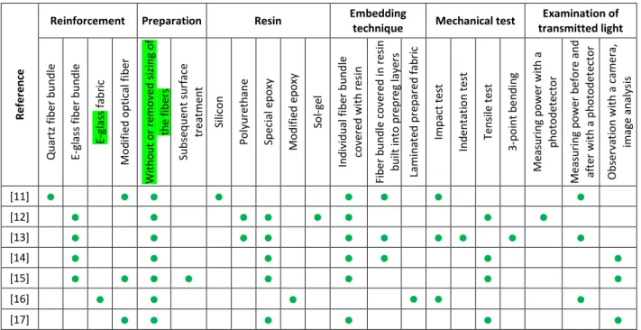
The continuous reinforcing glass fibers of composites are considerably different from optical fibers due to their different manufacturing technology, composition and structure, but in special resin systems and with special preparation, they can be made capable of transmitting light. A change in the power of light transmitted by the single fibers (e.g. in the case of fiber breaking) can indicate a change in the structural properties of the material in the vicinity of the monitored reinforcing fiber bundle, and this can be used for cure monitoring [9, 10], or even to identify the location of damage. Table 1 summarizes the materials and test methods of publications focusing on indicating damage.
4
Reference
Reinforcement Preparation Resin Embedding
technique Mechanical test Examination of transmitted light
Quartz fiber bundle E-glass fiber bundle E-glass fabric Modified optical fiber Without or removed sizing of the fibers Subsequent surface treatment Silicon Polyurethane Special epoxy Modified epoxy Sol-gel Individual fiber bundle covered with resin Fiber bundle covered in resin built into prepreg layers Laminated prepared fabric Impact test Indentation test Tensile test 3-point bending Measuring power with a photodetector Measuring power before and after with a photodetector Observation with a camera, image analysis
[11] ● ● ● ● ● ● ● ●
[12] ● ● ● ● ● ● ● ●
[13] ● ● ● ● ● ● ● ● ● ●
[14] ● ● ● ● ● ● ●
[15] ● ● ● ● ● ● ● ●
[16] ● ● ● ● ● ●
[17] ● ● ● ● ● ●
Table 1 Publications investigating how reinforcing glass fibers can be used for damage analysis
Hayes et al. [11] coated a bundle of quartz reinforcing fibers with resin of a low refractive index (after removing the sizing), and built them between carbon fiber prepreg layers.
Then they illuminated the fiber bundle, which transmitted the light and successfully indicated damage resulting from impact. The power of light transmitted by the fiber bundle before and after loading was compared. Several researchers used cheaper E-glass fiber bundles with the sizing removed in special (or modified) resin systems of low refractive index and showed that the power of transmitted light changed as a result of damage [12-16]. They also used the “sensor” (the prepared unsized fiber bundle in a low refractive index resin) built between prepreg layers to show damage to the composite.
Rauf et al. [16] impregnated E-glass reinforcing fabric (with the sizing removed) with modified epoxy resin and showed that the method can be used to identify and locate impact damage. Malik et al. [15, 17] built optical fibers into a composite and examined their light transmitting ability during tensile testing. The optical fibers were specially
5
made; their diameter was of the same order of magnitude as the diameter of the reinforcement fibers. Their advantage to E-glass fibers is that their light transmitting ability is not limited to a few meters, therefore they require lower illuminating light power to operate. Their disadvantage, however, is that they have to be specially made.
In sum, although numerous researchers have investigated the light transmitting ability of the glass fiber bundles and specially made glass fibers in special resins and pointed out that “sensors” made this way are able to indicate damage in the composite structure, the authors did not concentrate on the use of the method in general applications. Almost all of the researchers used a specially prepared single fiber bundle which was not the part of the reinforcing fabric of the composite, and the sizing of reinforcing fibers was removed in the experiments. However, the sizing does not only hold together and protect the fiber bundle during processing steps, such as weaving, but also considerably improves adhesion between fiber and matrix. Therefore removal of the sizing reduces the load- bearing capacity of the composite structure. In addition, it should be noted that the sizing can deteriorate the light transmission capability of the fibers as its refractive index is higher than the refractive index of the glass fibers. In the above-mentioned publications, the resins used were made for special applications or they were modified, but thanks to the wide range of refractive indexes resins have [18], a carefully selected general-purpose resin can be applied for the matrix of the composite. In the publications, the authors identified the change in the transmitted light power mostly as a result of fiber breaking;
they did not concentrate on the distinction of the effect of different types of failure (such as fiber–matrix debonding and fiber breaking).
In our earlier publications [19-21] we showed that a reinforcing fiber bundle can be made capable of transmitting light in a properly selected general-purpose matrix material, even
6
without special preparation. We showed that if an arbitrarily chosen fiber bundle of the reinforcing glass fabric is illuminated and the power of the light transmitted by the fiber bundle is measured, the measurement results can indicate the direction of the load and the resulting strain can be identified before the structure is damaged [20, 21].
In this publication, we show that an arbitrarily chosen fiber bundle of the reinforcing glass fabric of a general-purpose polymer composite structure can be used for damage analysis.
This phenomenon can be used to distinguish fiber breaking and fiber-matrix debonding if the ends of the illuminated fibers are also examined with a microscope. Our goal is to provide the reinforcing glass fibers of composites with an additional function, without removing the sizing of the fibers, which results in not only multifunctional [22-24] but also self-sensing composites; this way, it is not necessary to build in an additional health monitoring sensor.
2. Materials and equipment used
We manufactured the specimen using E-glass fabric reinforcement which had a refractive index of 1.56, a density of 2.54–2.60 g/cm3. It was [0,90] plain weave (weft direction 400 tex; warp direction 300 tex). Its surface density was 320 g/m2±6% (STR 014-320-125, Krosglass, Poland). We used the glass fabric as it came from the factory; we did not modify it in any way before building it in (we did not remove the silan sizing of the fibers). The matrix (based on our earlier work [19]) was MR3012 epoxy resin (Ipox Chemicals, Germany) and the curing agent was MH3122 (Ipox Chemicals, Germany) in a weight ratio of 100:40. This general-purpose transparent resin system can be produced from potentially renewable resources and has a refractive index of 1.52.
7
Our goal was to produce a multifunctional composite specimen in which an arbitrarily chosen fiber bundle of the continuous reinforcing glass fabric is used as sensor, therefore the selected fiber bundle is an integral part of the reinforcing structure, not an additional, separate element. We made the specimen with the following steps to facilitate coupling of the light of the light source to the fiber bundle and measuring the power of light transmitted by the fiber bundle:
- We guided two ends of an arbitrarily chosen fiber bundle of the reinforcing fabric ply (see Fig. Hiba! A hivatkozási forrás nem található. (a)) out of the fabric, leaving the tested length (50 mm) of the bundle within the fabric (see Fig. Hiba!
A hivatkozási forrás nem található. (b)).
- We positioned both ends of the fiber bundle within optical connectors of given diameter for coupling the light from the source and to the signal processing unit in such a way that the axes of the two ends of the fiber bundle are at an angle. As a result, the direction of illumination did not coincide with the axis of the fiber bundle at the other end, where light power was measured. This way, the light coming from the light source and light transmitted by the resin did not interfere with the measurement results. The optical connector was a cord-end terminal with an inner diameter of 1 mm (±0.1 mm) (Fig. Hiba! A hivatkozási forrás nem található. (c)).
- The composite sheet was laid up by hand and cured in a furnace at 70°C for 4 hours (Fig. Hiba! A hivatkozási forrás nem található. (d)), then both ends of the fiber bundle in the cord-end terminal were polished to optical quality with dry polishing papers (grades: 30 µm, 6 µm and 3 µm), and wet polishing papers
8
(grades: 1 µm, and 0.2 µm) (see Fig. Hiba! A hivatkozási forrás nem található.
(e)).
- After curing finished, 170 mm long and 25 mm wide specimens were cut for tensile testing and 100 mm long and 25 mm wide specimens were cut for the fiber- matrix debonding test from the 0.65±0.04 mm thick composite sheet.
Fig. 1 The steps of preparing a multifunctional composite specimen: (a): arbitrarily chosen fiber bundle in the composite (b): the two ends of the bundle are pulled out of the fabric , (c):
they are connected to a cord-end terminal, (d): the fabric is impregnated with resin, (e): the ends of the fiber bundle are polished and (f): the ends of the bundle are connected to an optical fiber, (g): specimen with end-tabs for the tensile test, (h) specimen with fastener for
the fiber-matrix debonding test
(1 - glass fabric, 2 - selected fiber bundle, 3 - cord-end terminal, 4 - resin, 5 - optical fiber, 6 - optical connector, 7 - direction of light, 8 - composite plate for fixing the specimen, 9 -
adhesive, 10 - clamping device, 11 - fastener, 12 - masking tapes)
For the tensile test, 60 mm long and 25 mm wide end-tabs were bonded on the composite specimen after polishing. The tabs were cut from a 3.7 mm thick composite sheet, which
9
contained 6 layers of glass fabric. For the investigation of fiber bundle-matrix debonding, the specimen was bonded to a 100 mm x 100 mm carrier sheet cut out from the 3.7 mm thick composite sheet. On the other side of the specimen, we used masking tapes to bond the base plate of a metal fastener (SM1/B32-M8x25, BigHead, UK) on a 3 mm wide and 32 mm long area above the illuminated fiber bundle. This fastener is widely used for connecting composite parts; it has a 32 mm x 32 mm x 1.5 mm metal base plate and a welded threaded pin. The adhesive used was AcraLock SA 10-05 BLK (USA). Each test was performed on 3 specimens.
In each test, the fiber bundle of the loaded specimen was illuminated, a signal evaluation instrument assessed the change in the intensity of transmitted light, and a signal transmitting element was used to connect the fiber bundle with the light source and the instrument. The light source was 532 nm wavelength (green) frequency-doubled Nd:YAG laser (Suwtech, dpgc-2250, USA) and for evaluation we used high-sensitivity optical power meter (Coherent, OP-2VIS, USA) and a digital microscope (Keyence, VHX-6000, Japan) connected to a lens system (Keyence, VH-Z100UR, Japan). The evaluating software of the power meter (Coherent FieldMax II) recorded the measured power values at 1 Hz, while the digital microscope had a resolution of 1600 x 1200 pixels and recorded 15 images per second.
The fiber bundle was connected to the light source and the power meter with a 400 mm long polymer optical cable (outer diameter 1500±90 µm, core diameter 1470±90 µm,
refractive index of the core 1.492, Tru Components, VD-1500, Germany). The core diameter of the polymer cable was larger than the inner diameter of the connector and both ends of the optical cable were polished. We made special connectors to connect the
10
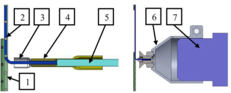
glass bundle in the cord-end terminal to the optical cable and to the lens system of the digital microscope (Fig. 2).
Fig. 2 Elements of connection of the fiber bundle: 1 - specimen, 2 - illuminated fiber bundle, 3 - the end of the fiber bundle in the cord-end terminal, 4 - self-made connector to connect
the cord-end terminal and the optical cable, 5 - optical cable, 6 - self-made adapter to the digital microscope, 7 - lens system of the digital microscope with the connector and the
specimen
The tensile tests were performed on a computer-controlled universal testing machine (Zwick, BZ020/TN2S, Germany).
3. Using the reinforcing fiber fabric to detect fiber breakage in the composite
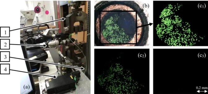
To examine fiber breakage, we performed a tensile test on the specimens with the tabs at a speed of 0.5 mm/min in the layout in Fig. 3. The tested fiber bundle was illuminated with an Nd:YAG laser through a polymer optical fiber, while the other end was examined with the above-mentioned digital microscope, with the fixture shown in Fig. 2. The individual fibers of the glass fabric of the composite can be clearly seen thanks to the illumination. During the tensile test, the individual fibers did not stop transmitting light— they continued to shine almost at the same brightness. As expected, the specimen broke
11
suddenly, therefore the state during the breakage can only be seen in one frame (breakage occurred during the time of two frames ~0.13 sec) (Fig. 3).
Fig. 3 Measurement layout (a) and the microscopy images of the end of the fiber bundle before loading (b) and at the “moment” of breakage (c1, c2, c3) (there was ~0.07 second between the frames) (1 – upper clamp of the tensile tester, 2 - digital microscope, 3 - optical
cable, 4 - light source)
The single fiber ends disappear when the bundle breaks but since breaking occurred in a short time, the test did not allow for a detailed investigation of the fiber breakage process.
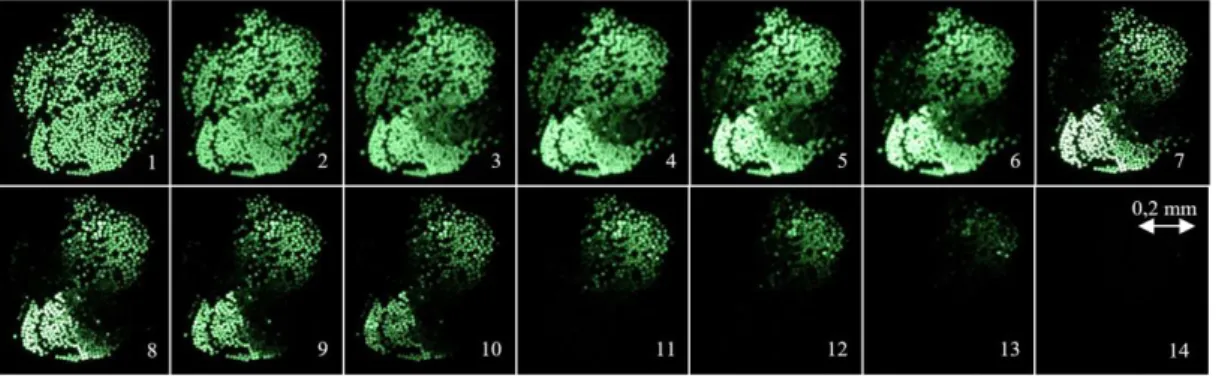
Therefore, in our next test, we cut through the illuminated fiber bundle within the fabric close to the cord-end terminal with a razor blade in several steps (starting from the upper surface of the specimen), and recorded the images with the digital microscope (Fig. 4).
12
Fig. 4 The ends of the single fibers get dimmer and dimmer as a result of cutting through the fibers
The images (from 1 to 14 in Fig. 4) clearly show how the shining fiber ends dim and disappear after each cutting step. For better visibility, Fig. 5 shows three consecutive cutting steps.
Fig. 5 Dimming and disappearing fiber ends (within the red circle) as a result of consecutive cutting steps (from 7 to 9)
The enlarged images clearly show fiber ends that get dimmed or disappear as a result of cutting. The reason for dimming is that some fibers were only partly damaged and also light was coupled from undamaged fibers to cut fibers and was transmitted by them.
While at the beginning, the fiber ends of the illuminated fiber bundle emitted light with
13
approximately the same intensity, fiber breaking resulted in a considerable difference in the intensity of light emitted by the fiber ends. The tests proved that the change in the power of the transmitted light makes the method suitable to indicate damage (e.g. single fiber breakages) within the illuminated bundle.
4. Using the reinforcing glass fabric of composites to show fiber-matrix debonding
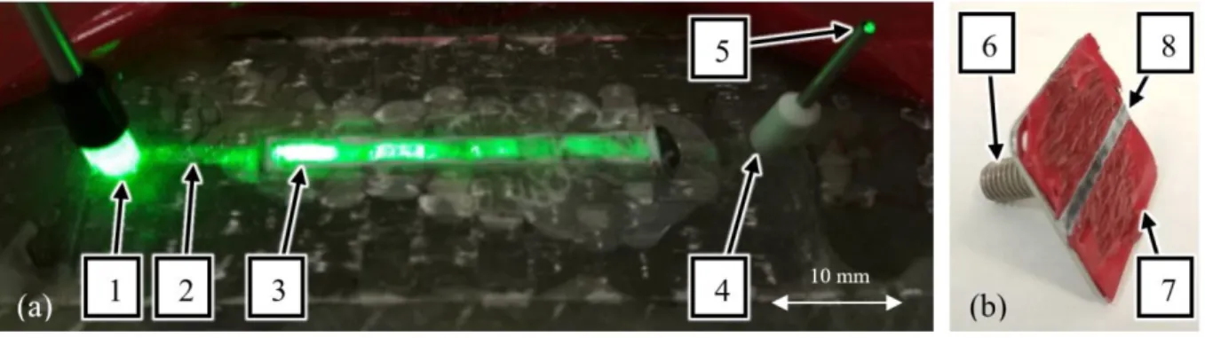
Fiber-matrix debonding is a damage mode of composites which is hard to identify. We tested the possibility of indicating this kind of damage with an illuminated fiber bundle and examined the effect of fiber-matrix debonding. The specimen we used is described in section 2. Materials and equipment used. We applied tensile load on the fastener with the help of a threaded pin clamped in the tensile tester, while the carrier composite sheet (with the specimen bonded on it) was fixed with a clamping device. The fastener was torn off the specimen in several loading steps, while the power of transmitted light was measured with the power meter (Fig. 6). Loading speed was 0.5 mm/min. When the maximum force in a given cycle was reached, the force was kept for 10 seconds, then the load was reduced to a speed of 0.5 mm/min. The initial maximum force of uploading was 500 N; it was increased by 500 N in each cycle.
14
Fig. 6 Layout for testing matrix tear off (a) and the image of the specimen (b) (1 - illumination, 2 - power meter, 3 - clamping device to fix the specimen, 4 - insert, 5 - polymer
optical cable, 6 - red masking tapes)
The adhesive we used proved to be the right choice because the adhesion between adhesive-metal sheet of the fastener and adhesive-matrix of the specimen was larger than the adhesion between the matrix of the specimen and the surface of the fiber bundle. This was obvious after failure (tearing off the insert) because the matrix of the specimen was torn off the fiber bundle. The illuminated fiber bundle was visibly brighter where the matrix was torn off than where the matrix was intact (Fig. 7).
Fig. 7 The illuminated fiber bundle under the torn-off matrix (a) and the matrix material stuck to the torn-off metal plate in a 3 mm wide band, between the red masking tapes (b) (1 - the point where the light enters the fiber bundle; 2 - the illuminated fiber bundle as seen faintly under the matrix; 3 -the illuminated fiber bundle under the torn-off resin; 4 - the cord-end terminal to connect the fiber end optically; 5 - the end of the illuminated fiber bundle; 6 – the
torn-off steel plate; 7 - red masking tapes; 8 - matrix torn off in a width of 3 mm)
Fig. 8 shows how the power of transmitted light is reduced at the end of the fiber bundle according to equation (1).
Reduction in light output = (P0-P)/P0 (1)
15
where P0 is the power of light transmitted by the fiber bundle before it was loaded, and P is the power of light transmitted by the fiber bundle under load.
Fig. 8 Reduction in the power of the transmitted light due to matrix tear-off as a function of time (a) and force (b) (the values of the different specimens are marked with different
colors)
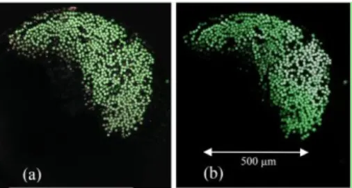
The test results show that during loading the power of transmitted light decreases continuously, then, when the load is reduced, transmitted light power increases slightly (less so than it decreased as the load was increased), and when loading stops, the power of transmitted light does not return to its original value—there is some permanent power loss. At the end of the fiber bundle, the power of transmitted light can be measured even when the matrix is torn off. Tearing off the matrix leads to a reduction of 30–50% in transmitted light power. This could mean that 30-50% of the single fibers are broken, those fibers that were connected to the torn-off matrix. To test this hypothesis, we compared the microscope images of the illuminated fiber bundle in the specimens before the test and after breaking (Fig. 9).
16
Fig. 9 Microscope images of one end of the illuminated fiber bundle before- (a) and after fiber-matrix debonding (b)
The images show that the number of bright fiber ends is approximately the same before and after the test (compared to Fig. 4, where disappearing fiber ends are clearly identifiable); there are hardly any fiber ends that are dark (which would indicate breakage of the single fiber). Therefore, the permanent 30–50% decrease in transmitted light power was not caused only by the breakage of single fibers (because then there would be far more “dark” fiber ends). As a result of matrix tear-off, the optical properties of the fibers are modified by surface defects, cracks, and a rising number of microbended and macrobended sections. Inhomogeneities on the fiber surface modify the total reflection locally, and inhomogeneities in the volume of the fibers act as scattering centres. These inhomogeneities, due to fiber–matrix debonding, caused an increased amount of light to exit the illuminated fiber bundle along the region where the fibers are debonded from the matrix. This is supported by the fact that after the matrix is torn, some fiber ends shine far less intensively than others (before loading there was not such a big difference). These microscopic and macroscopic inhomogeneities, which decrease the light transmitting ability of the tested fiber bundle, already appear at a smaller load than that necessary for tearing off the matrix. This is indicated by the permanent decrease of transmitted light power in the first and second cycle of measurements.
17 5. Conclusions
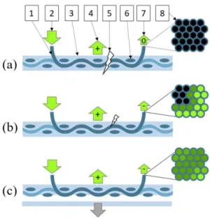
We proved that the fiber bundle of the reinforcing glass fabric of the polymer composite structure can be used to indicate damage to the composite. For the matrix of the composite, a carefully selected general-purpose resin system can be applied and the sizing of the fibers does not have to be removed, so the reinforcing glass fabric can be used without any special surface preparation. We demonstrated a simple way to illuminate an arbitrarily chosen fiber bundle of the fabric. With the microscopic examination of the ends of the illuminated fibers, fiber breaking and fiber-matrix debonding can be distinguished. When the illuminated fiber bundle of the composite structure breaks, the light leaves the fiber bundle at the point of breakage and therefore the power of emitted light at the end of the fiber bundle decreases to zero. Therefore, breakage is indicated by the reduction of transmitted light power to zero (Fig. 10 (a)). The location of breakage is indicated by the visible light emitted by the fiber bundle at that point.
Fig. 10 The transmission of light stops as a result of the breakage of the illuminated fiber bundle (a), transmitted light power is decreased when the fiber bundle partially breaks (b) transmitted light power is decreased when the matrix is torn off (c) (1 - an arbitrarily chosen
18
fiber bundle of the reinforcing glass fabric, 2 - illumination, 3 - matrix, 4 - the power of light coupled out on the surface of the fiber bundle, 5 - damage; 6 - fiber bundles crossing the
illuminated fiber bundle of the glass fabric, 7 - the power of light transmitted by the illuminated fiber bundle stops [marked with “0”], or decreases [marked with “-“], 8 - light
transmitted by the single fibers of the fiber bundle)
If the fiber bundle is partially broken, it causes a permanent reduction in the power of transmitted light by the fiber bundle. In the case of partial breakage, the microscope image of the end of the illuminated fiber bundle clearly shows single fiber ends that are dark as a result of the breakage (Fig. 10 (b)). A load causing fiber-matrix debonding also leads to a permanent decrease of transmitted light power. The reason for this is that the microscopic and macroscopic failures due to the load cause the power of light coupled out of the fiber bundle to increase, and therefore the power of transmitted light by the fibers decreases permanently. In the case of fiber-matrix debonding, the shining of single fiber ends does not cease, but is reduced compared to their original brightness (when the fibers are undamaged). Brighter and dimmer fiber ends appear, which indicates debonding or that the matrix is torn off the illuminated fiber bundle (Fig 10 (c)).
The demonstrated phenomenon provides the reinforcing glass fibers of composites with an additional function, which results in self-sensing composites; this makes the application of an additional health monitoring sensor unnecessary.
Acknowledgments
This work was supported by the National Research, Development and Innovation Office (NKFIH) [OTKA K 116070 and K120592; NVKP_16-1-2016-0046; and 2017-2.2.4- TÉT-AT]; the Higher Education Excellence Program of the Ministry of Human Capacities in the framework of the Nanotechnology research area of the Budapest
19
University of Technology and Economics [BME FIKP-NANO]; and the National Research, Development and Innovation Fund [TUDFO/51757/2019-ITM, Thematic Excellence Program].
6. References
[1] Struzziero G, Teuwen JJE, Skordos AA. Numerical optimisation of thermoset composites manufacturing processes: A review. Composites Part A 2019;124:105499.
[2] Larrañaga-Valsero B, Smith RA, Tayong RB, Fernández-López A, Güemes A.
Wrinkle measurement in glass-carbon hybrid laminates comparing ultrasonic techniques: A case study. Composites Part A 2018;114:225-240.
[3] Kovács L, Romhány G. Derivation of ply specific stiffness parameters of fiber reinforced polymer laminates via inverse solution of classical laminate theory.
Periodica Polytechnica Mechanical Engineering 2018;62:158-164.
[4] Lopes H, Ribeiro J. Structural health monitoring in composite automotive elements. In: Carmo J, Ribeiro J, editors. New advances in vehicular technology and automotive engineering. InTech Edition, 2012. p. 286-302.
[5] Glisic B, Inaudi D. Fibre optic methods for structural health monitoring. John Wiley & Sons Ltd., New York 2007. p. 154-196.
[6] Tsai JT, Dustin JS, Mansson JA. Cure strain monitoring in composite laminates with distributed optical sensor. Composites Part A 2019;125:105503.
[7] Saeter E, Lasn K, Nony F, Echtermeyer AT. Embedded optical fibres for monitoring pressurization and impact of filament wound cylinders. Composite Structures 2019;210:608-617.
20
[8] Shivakumar K, Emmanwori L. Mechanics of failure of composite laminates with an embedded fiber optic sensor. Journal of Composite Materials 2004;38:669–680.
[9] Wang L, Tomlin A, Pandita SD, Gupta BD, Malik SA, Hudson M, Curtis PT, Fernando GF. In-situ monitoring of cross-linking reactions using E-glass fibres and evanescent wave spectroscopy. Sensors and Actuators B: Chemical 2016;236:358- 366.
[10] Kister G, Ralph B, Fernando GF. A chemical sensor based on conventional E-glass fibres. Advanced Engineering Materials 2001;3:711-713.
[11] Hayes S, Liu T, Brooks D, Monteith S, Ralph B, Vickers S, Fernando GF. In situ self-sensing fibre-reinforced composites. Journal of Smart Structures and Materials 1997;6:432-440.
[12] Kister G, Wang L, Ralph B, Fernando GF. Self-sensing E-glass fibres. Optical Materials 2003;21:713–727.
[13] Kister G, Ralph B, Fernando GF. Damage detection in glass fibre-reinforced plastic composites using self-sensing E-glass fibres. Smart Materials and Structures 2004;13:1166–1175.
[14] Kister G, Badcock R, Fernando GF. A novel technique to study the fracture of E- glass fiber. Journal of Materials Science 2004;39:1425–1428.
[15] Malik SA, Wang L, Mahendran RS, Harris D, Ojo SO, Collins D, Paget M, Pandita SD, Machavaram VR, Fernando GF. In-situ damage detection using self-sensing composites. In: Sensors and Smart Structures Technologies for Civil, Mechanical, and Aerospace Systems, Proceedings of SPIE Smart Structures and Materials + Nondestructive Evaluation and Health Monitoring, San Diego, 1 April 2009. 7292.
21
[16] Rauf A, Hand RJ, Hayes SA. Optical self-sensing of impact damage in composites using E-glass cloth. Smart Materials and Structures 2012;21:45021.
[17] Malik SA, Wang L, Curtis PT, Fernando GF. Self-sensing composites: In-situ detection of fibre fracture. Sensors 2016;16:615.
[18] Aloui F, Lecamp L, Lebaudy P, Burel F. Refractive index evolution of various commercial acrylic resins during photopolymerization. Express Polymer Letters 2018;12 (11):966-971.
[19] Hegedűs G, Sarkadi T, Czigány T. Analysis of the light transmission ability of reinforcing glass fibers used in polymer composites. Materials 2017;10:637/1- 637/9.
[20] Hegedűs G, Sarkadi T, Czigány T. Self-sensing polymer composite: White-light- illuminated reinforcing fibreglass bundle for deformation monitoring. Sensors 2019;19:1745 p8.
[21] Hegedűs G, Sarkadi T, Czigány T. Multifunctional composite: Reinforcing fibreglass bundle for deformation self-sensing. Composites Science and Technology 2019;180:78-85.
[22] Marques AT, Ferreira ADBL, Nóvoa PRO. Multifunctional material systems: A state-of-the-art review. Composite Structures 2016;151:3-35.
[23] Fredi G, Dorigato A, Pegoretti A. Multifunctional glass fiber/polyamide composites with thermal energy storage/release capability. Express Polymer Letters 2018;12:349–364.
22
[24] Forintos N, Czigany T. Multifunctional application of carbon fiber reinforced polymer composites: Electrical properties of the reinforcing carbon fibers – A short review. Composites Part B 2019;162:331-343.