Original Article
Biomechanical assessment of orbital fractures using patient-specific models and clinical matching
A. Darwich
a,b, A. Attieh
c, A. Khalil
d, S. Sza´vai
e, H. Nazha
e,*
aFacultyofBiomedicalEngineering,Al-AndalusUniversityforMedicalSciences,Tartous,Syria
bFacultyofTechnicalEngineering,UniversityofTartous,Tartous,Syria
cFacultyofDentistry,Al-AndalusUniversityforMedicalSciences,Tartous,Syria
dFacultyofDentistry,TishreenUniversity,Lattakia,Syria
eFacultyofMechanicalEngineeringandInformatics,UniversityofMiskolc,Miskolc,Hungary
1. Introduction
Orbitalfracturesarecommonfacialfracturesinmaxillofacial surgery,andtheyhaveaestheticandfunctionalconsiderationssoit is important to understand their mechanisms for effective prevention and treatment [1,2]. Orbital walls fracture happens eitherisolatedwhichconstitute4–16%offacialfractures,oraspart ofotherfractureslikezygomatico-maxillarycomplexfracturesor naso-orbital-ethmoidfractures. Theincidenceofthesefractures approaches30–55%[3].
Isolatedorbitalfracturesoftendescribedbytheirlocationand sizeofthedefect.Threepatternsofisolatedorbitalfractureshave beendescribed:linear,blow-out,and complex[4]. Zygomatico- maxillary complex fractures are the most common fractures involving orbital fractures.Naso-orbital-ethmoid fracturesmost often occur blunt trauma to the midface, and usually involve orbitalwallsfractures[3].
Theorbitisshapedlikepyramidwithitsbaseisformedbythe orbitalrimsanteriorly.Thebonyorbitisconsistedofsevenbones:
frontal, zygomatic, lacrimal, maxillary, ethmoid, sphenoid, and palatal.Ithasfourwallsvaryin thicknessandstrength.Medial wall,whichisthethinnest,iscomposedofsphenoid,lacrimal,and palatalbones.Lateralwallwhichiscomposedofzygomaticand sphenoid.Orbitalroofiscomposedoffrontalboneandsphenoid bone and it separates the orbit from anterior cranial fossa. In addition,orbitalflooriscomposedofmaxillary,zygomaticoand palatalboneanditformsthemaxillarysinusroof[3].Orbitalfloor fractureseithersolely(blow-outfracture)oraspartofzygomatico- maxillarycomplex(ZMC)fractures.
Severalstudieshavebeenconductedtoillustratethemecha- nismsoforbitalfloorfractures[4,5].Orbitalfractureshappenwhen increasedpressurewithinthecomponentsoftheorbitcausesthe fragilewallsoftheorbittofracture[6].InthecaseofZMCfractures, infraorbitalrim and orbitalfloorare bend.Medial orbitalwall fractureshappeneitherwithblow-outfractures,oraspartofnaso- orbitoethmoid complex fractures [7]. This complex consists of manyanatomicalstructuresanditisadjacenttotheanteriorskull base where fractures extended to this area might have severe ARTICLE INFO
Articlehistory:
Received14November2020 Accepted28December2020
Keywords:
Orbitalfractures Hydraulicmechanism Bucklingmechanism Finiteelementanalysis
ABSTRACT
Introduction:Orbitalwall fracturesconsideroneofthemostcommonfracturesinthemaxillofacial trauma.Thesefracturescausedbytwomechanisms,thebucklingmechanismandhydraulicmechanism.
Thisstudyaimstocomparebetweenthetwomechanismsintermsofintensityandextensionusingthe finiteelementsmethod.
Materialandmethods:Three-dimensionalmodeloftheskullwasgeneratedusingcomputedtomography dataofyoungmalepatient.Virtualloadswereappliedontheeyeballandtheinfra-orbitalrimseparately.
VonMisesstresseswereexaminedineachsimulation.
Results:Thesimulationpredictedfracturesontheinfra-orbitalrimandorbitalfloorwhensimulatingthe hydraulic mechanism, and on the orbital floor and mesial wall when simulating the buckling mechanism.
Conclusion: Biomechanical studies are essential part in understanding maxillofacial fractures mechanisms.Theresultsconfirmedandascertainedwhatisseenclinically,andexplainedclearlythe twomechanismsoforbitalfractures.
C 2020PublishedbyElsevierMassonSAS.
* Correspondingauthor.
E-mailaddress:hasan.nazha@uni-miskolc.hu(H.Nazha).
Availableonlineat
ScienceDirect
www.sciencedirect.com
https://doi.org/10.1016/j.jormas.2020.12.008 2468-7855/C 2020PublishedbyElsevierMassonSAS.
Pleasecitethisarticleas:A.Darwich,A.Attieh,A.Khaliletal.,Biomechanicalassessmentoforbitalfracturesusingpatient-specific modelsandclinicalmatching,JStomatolOralMaxillofacSurg,https://doi.org/10.1016/j.jormas.2020.12.008
consequences[8].Lateralorbitalwalltraumaisusuallyaccompa- niedwithZMCfracturesaslargepartoflateralorbitalrimisfrontal processofzygoma.
TheZygomatico-MaxillaryComplex(ZMC)isafacialbonewith aquadrupedshape.Itarticulateswiththefrontalbone,temporal bone,maxilla,andsphenoidbone,andservesasthemainbridge betweenthesebones[9].Itisanaestheticandfunctionalunitofthe facialskeleton.Afterthenasalbone,theyconsiderthesecondmost commonlyfracturedsites[10].
Finite element models showeda high degree of success in predictingthebiomechanicalbehaviorofskeletalbonessuchas longbonesandiliac[11,12].Thistechniquereliesonreplacement ofcomplicateddifferentialequationsofirregularshapeswithan extensive system ofalgebraic equations,which representsmall geometricentitiesthatcanbesolvedbyacomputer[13].Inthis method, the studied structure is modeled into a mesh of tetrahedral elements that are connected together with nodes.
Thephysicalpropertiesoftheseelementsareassigned,anumber oftheseelementsareconstrainedandknownforcesareapplied andthestressesandstrainsarecalculatedateachnodeandineach element[14].
Simulationoffacialfracturesusingfiniteelementsmethodcan help tounderstand their biomechanical behavior and improves currentsurgicaltreatmentprotocols.Theaimofthis studyisto investigate the biomechanical behavior of orbital walls when sustainingasingleloadusingthefiniteelementsmethod.
2. Materialsandmethods
Finite element analysis was used to investigate fracture patternsoforbitalwalls.The0.6mmthicknessDICOMfileswere obtainedfromCT scanner(Siemens SOMATOM)of35 yearsold malepatient,wherethemalesfromthisagerangearethemostof thoseexposedtofacialtrauma[15].Thedatawasobtainedfrom RadiologyDepartmentat TishreenUniversity Hospital,Lattakia, Syria.PatientapprovalwastakentousehisCTdatainthisstudy.
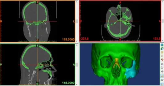
DICOMfileswereimportedintoMIMICSsoftware(Materialise,inc, Belgium)toIsolatetheboneusingTresholdingalgorithm,builda 3DmodeloftheskullasshowninFig.1,andEmitthemandible fromtheskullbecauseourstudyfocusesontheorbitonly.
3-MATIC software (Materialse, inc, Belgium) was used in exportingthe3Dmodeltodesignaspherethattouchestheinner wallsoftheorbit,thussimulatingtheeye,meshthesurface,where itwasdividedintotriangularelementsconnectedtoeachotherby nodes(Fig.2A),Createvolumemeshbasedonthesurfacemesh (dividingthebodyintotetrahedralelementsthatareconnected withnodes)which comprised560,000elements,andconvert4- nodedtetrahedralelementsinto10-nodedtetrahedralelements whicharebetterforanalysisresultsaccuracy.
3-MATICfile(.cdb)wasexportedtoANSYSsoftware18.1(Ansys inc,USA)forfiniteelementanalysisasfollows:Theareaswherethe loadswill beappliedweremarked(ontheinfra-orbital, supra- orbital,medial-orbital,lateral-orbitalrimsandthecenterofthe
Fig.2.(A)Skullsurfaceandvirtualeyeballandsurroundingfatin3-maticsoftware,(B)markedsitesinAnsyswhereloadswasapplied.
Fig.1.MIMICSsoftware,usedin3Dmodelconstruction.
virtualeyeball)asshownin(Fig.2B).Markareastobeconstrained (thetwooccipitalcondylesoftheskull).
Materialpropertieswereassignedforboththeskullboneand the eyeball (density, Young‘s modulus and Poisson ratio) as follows:Youngmoduluswascalculatedbasedondensityvalues according to Morgan approach [16]. Each element of the volumetricmeshwasassignedwithindividualvaluesforphysical properties,includingbothdensityvaluesandYoungmoduluswith the help of APDL Script in ANSYS software. Poisson ratio was assignedto0.3accordingtoHuskes[17].Thevirtualeyeballwas assignedtoYoungmodulusofWaterat2000MPaduetoitshigh watercontent,anddensityofwaterisknowntobe997kg/m3[17].
Poisson ratio of the entire eyeball was obtained from medical literature at 0.47 [18]. The contact surface between skull and virtual eyeballwasmodeledusingcoulomb frictionmodel.The coefficientoffrictionforthis contactwasdefinedwith0.3[19].
Fivestudydesignswerechosentosimulatewhatisseenclinically:
Applyloadtothevirtualeyeball,applyloadtotheinfra-orbitalrim, applyloadtothemedial-orbitalrim,applyloadtothesupra-orbital rim,andapplyloadtothelateral-orbitalrim.
Orbitalfatwastakenintoaccountastheroleofthefatiscrucial to explain the hydraulic mechanism of orbital fractures as indicated in Folettiet al.[20]. Virtual staticloads wereapplied ineach studydesign alongY-axiswhichisperpendiculartothe surface onwhich theloadwasapplied.Theloadwasgradually increasedby100Natatime untilwereachedvonMisesstress valueof153MPaorabove.Whenresultantstressesexceededthe valueof153MPa,thecausalloadwasrecordedandsimulationwas stopped ineach design. We assumedthat thevon Misesstress above153MPawasthecriteriaoffailureforskullbonesaccording toNagasaoetal.study[21],wherethisstressvalueiswhenthe bonechangefromtheelasticphasetotheplasticphaseandthen begins to fail (fracture). The skull was fixed at the occipital condylesinalldegreesoffreedom.
3. Results
VonMisesstresswasevaluated,whichcanbeusedtopredict material failure successfully. Results were plotted as color spectrumrangedfrombluetored,whereredindicatesthehighest valueofcalculatedstress,andinthisstudyredcolorindicatethat stresshasreachedtheyieldstrength(153MPa)atwhichthebone begantofail(fracture).
3.1. Loadonvirtualeyeball
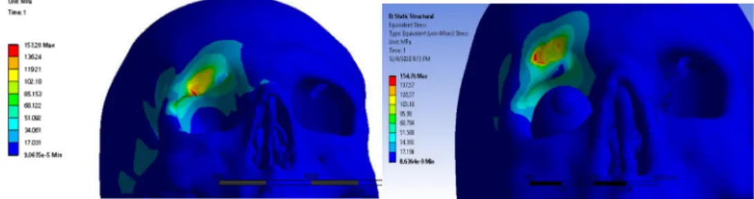
It has been found a maximum von Mises stress value of 155MPawhenapplyingaforceof7200Nontheeyeballalongthe Y-axisonthemarkedareaasshowninFig.3.Theanalysisresults revealed concentration of stresses in the orbital floor and the medialwalloftheorbit(Fig.3),withthehighestattheorbitalfloor indicating that the stresses are approaching or exceeding the 153MPathreshold,whichmeanswecanpredictafractureinthis area.Moreover,thepresenceoforbitalfatseemedtoincreasethe forcevalueuntilthefracturethresholdisreached(9000N).This pointouttoasignificantprotectiverole,whichtheorbitalfatmay play.Highstresseswereconcentratedatorbitalmedialwalland floor;theyalsospreadtoskullbasewithoutreachinghighvaluesas showninFig.3.
3.2. Loadontheinfra-orbitalrim
It has been found a maximum von Mises stress value of 156MPawhenapplyingloadof8600Nattheinfra-orbitalrim alongtheY-axisonthemarkedareaasshowninFig.4.
Simulation revealed concentration of stresses in the infra- orbitalrimandfrontsectionoftheorbitalfloor,whereredspots indicate that the stresses are approaching the threshold of 153MPa,which meanswe can predicta fracture in thesetwo
Fig.4.Thedistributionofstresseswhentheforcewasappliedontheinfra-orbitalrimwithout(left)andwith(right)thepresenceoforbitalfat.
Fig.3.Concentrationsofstressesatorbitalfloorandorbitalmesialwallwithout(left)andwith(right)thepresenceoforbitalfat.
regionsasshown inFig.4.Thepresenceoforbitalfatseemsto cause a stress concentration in in the orbital floor and tothe maxillarysinuswallsandskullbasewithoutreachingthe153MPa thresholdasshownintherightshapeofFig.4.
3.3. Loadonmedialorbitalrim
Whensimulatingablowonthemedialorbitalwall,ithasbeen foundthatvonMisesstressvalueof154MPawhenapplyingstatic loadof5400N.Thesestresseswereconcentratedatsiteofloadand spread to frontal, ethmoidal, and nasal bones. This simulation result issimilartowhatis foundinNOEfracturesasshown in Fig.5.Minimalroleoforbitalfathasbeennoticedinthistypeof loadingassimilarpatternshasappearedwithapproximativestress values.
3.4. Loadonthesupra-orbitalrim
Gradually increasing loads were (100N at time) on supra- orbitalrimtoinvestigateorbitalrooffractures.Themaximumvon Misesstressvalueof153MPawasfoundwhenapplyingloadof 9000Natthesupra-orbitalrimalongtheY-axisonthepre-defined areaFig.6.Stressesspreadtofrontalboneandorbitalroofwith
relativelyhighvalueswherethehigheststresswasatthesiteof load (orbital roof). Stress also spread to temporal bone. The presenceoforbitalfatcausedaslightelevationinstressvaluesand causedinamoreexpandedfracturepatternattheupperrimas seeninFig.6.
3.5. Loadonlateralorbitalrim
The maximum stress value of 154MPa was found when applyingloadof9300Natthelateral-orbitalrimalongtheY-axis onthemarkedareaasshowninFig.7.Stressesspreadtolargeareas ofthezygomatico-maxillarycomplex.Minimalroleoforbitalfat hasappearedinthisfracturepatternastheshapesandthevalues weresimilar.
Simulationshowsstressconcentrationinthelateralorbitalwall andrim.Thefracturescanbepredictedfracturesintheseareasand inthezygomatico-maxillarycomplex,asthesimulationshowsin Fig.7stressspreadtolargeareasofthiscomplex.
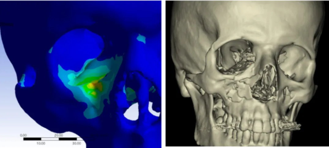
Fig. 8 shows a 19-years old patient withblow-out fracture caused by personal violence, CT scan revealed an orbital floor fracture which is corresponded to ourresults as shown in the sagittalcrosssection.Fig.9showstheclinicalvalidationoffracture stresseswhentheforcewasappliedonthelateral-orbitalrim.
Fig.5.Thedistributionofstresseswhentheforcewasappliedonmedialorbitalwallwithout(left)andwith(right)thepresenceoforbitalfat.
Fig.6.Thedistributionofstresseswhentheforcewasappliedonthesupra-orbitalrimwithout(left)andwith(right)thepresenceoforbitalfat.
Fig.7.Thedistributionofstresseswhentheforcewasappliedonthelateral-orbitalrimwithout(left)andwith(right)thepresenceoforbitalfat.
4. Discussion
Orbitalwallsfracturesoccurwhenthetraumaticforceaffects theorbitareaintheeventoftrafficaccidents,personalviolence, andwarinjuries[22,23].Mostexistingstudiesonorbitalfractures usedexperimentalmethodslike,hittingskullswithpre-measured objects [4–6,24–27]. However, it is difficult to maintain the continuityoftheexperimentconditionsbecausetheseconditions areeasilyaffectedbydifferencesin:impactpoints,angleofthe skull orskull stabilization.To solvethis problem,theskullwas simulated andperformed a finiteelementanalysison it, which allowsustoarrangeexactexperimentalconditionsincludingthe directionandintensityofimpactandtheregionstobestrucksowe usedfiniteelementanalysisforthisstudy.Thesimulationwasable toberepeatedmanytimesineachdesignuntilreachingthestress threshold describedbyNagasao etal.[21], which isdifficultto achieveusingexperimentalmethods.
Adetailedmodelof(theskullofyoungmale)wasabletobe generated with a dense volume mesh of about 560,000 finite elements.Usingsuchdensemodel,thedetailsofmideface,orbit, surrounding fat wererepresented in this study. Finite element models showed a high degree of success in predicting the biomechanical behavior of skeletal bones such as long bones andiliacbone[11,12].
Severalstudiesusedfiniteelementmethodtoillustrateorbital fractures.Nagasaoetal.[21]placed1085pointsonthesurfaceofa dry skull, then the coordinates of the marking points were measuredusinga3Dscanner,andthentheybuilta3Dmodelbased onthedatafromthescanner.Themodelusedinthisstudywas based on data froma computedtomography of a 35-years-old male, producing a model that represents the skull well and simulatesrealanatomy,includingthevariablebonethickness.
Thedetailedfiniteelementmodelusedforsimulation(560k elements),therelativelygoodresolutionofbonystructures,and materialassignmentofeachregionensuregoodrepresentationof the skull both anatomically and biomechanically. This good representationensuresgoodandreliableresults.
ThefirsttointroducethebucklingmechanismwasLeFort[28].
Thismechanismwasdefinedasthetransferofforceacrossthe bonefromtheinfra-orbitalrimtotheorbitalfloor.Thistheorywas widelyacceptedaswellasthehydraulicmechanismasacauseof orbital wall fractures [29]. Several experimental studies in literature support the buckling mechanism [4–6,24–27] they simulatedthefracturesoftheorbitbydroppingapre-measured weightorhittingthebonyorbitusinghammer.
Fujino et al. [24] conducted experiments using skulls without the eyes and the contents ofthe orbit, they hitthe skullsontheinfra-orbitalrim,thuseliminatingtheinfluenceof thehydraulicmechanism,focusingonthebucklingmechanism [25].Waterhouseet al.[5]alsodevelopeda newdevicethat allowsapoint-basedimpacttoaspecificareaoftheorbit.Using thisdevice,andstrikingtheeyeballortheinfra-orbitalrimon skulls individually, theyillustrated the fracture patterns for bothmechanisms.
Several studies simulated orbital wall fractures based on differentnumericalenvironmentsandunderdifferentbothstatic and dynamic scenarios. Takizawa et al. tried to explain orbital fractures,especiallythedynamiccharacteristicsoftheorbitatthe timeofthefracture.Theyanalyzedthedegreeandconcentrationof stresswithintheorbitdependingontheappliedloads,andthey found that direct force appliedagainst theinferior orbital rim resultedinincreasedstresswithinthelowerwalloftheorbit,and thatstresstendstoconcentrateinthethinnasalsideoftheorbital grooveaspressurewithintheorbitmounts[30].
Fig.8.(A)CTscanrevealedanorbitalfloorfracture,(B)19-yearsoldpatientwithblow-outfracturecausedbypersonalviolence,(C)theresultsinthesagittalcrosssection.
Fig.9.Theclinicalvalidationoffracturestresseswhentheforcewasappliedonthelateral-orbitalrim.
Themechanicalresponseofourskullmodelwascomparedwith theresultsofsimilarliteraturestudies.Thecurrentstudydiffers fromthestudy ofNagasaoet al.in whichtheskull modelwas dividedintoseveraltriangularpartsofdifferentthicknesses,while the model in the current study was based on CT images. This allowed to accurately detect the borders and to produce the thicknessofdifferentareasoftheskull[21].
Ontheotherhand,andincontrasttothestudyofNagasaoetal.
inwhichthenumberoffiniteelementswithintheskullmodelwas 248,000,thenumberoftheseelementsinthemodelstudiedinthis paperwasequalto560,000elements,whichwouldproducestress valueswithahigherspatialaccuracy[21].
Thisnumberofelementswasdeterminedbasedontheresults ofTaddeigroupresearchwhichcarriedoutanumericalapproach to analyze the influence of the number of finite elements on numerical results. From another side, high resolution results shouldbediscussedmorespecifically,asimagesaccuracyof1mm thicknessnecessitatesmodifyingtheimagesegmentationmanu- ally in order to preserve the continuity shape of the bone, especiallyintheregionsoforbitalandethmoidbones,inwhichthe thicknessoforbitalwallisapproximatelyequalto2.27mm[31].
Ourhitorientedtotheinfra-orbitalrimrevealedafracturein theinfra-orbitalrimandtheorbitalfloor,whichcorrespondstothe experimental model developed by Waterhouse et al. [5]. Our fracturepatterncorrespondsalsowiththeresultsofNagasaoand Miyamotostudy[21],wheretheyfoundthatfractureoccursinthe weakestpartsoforbit(orbitalfloor).
Schaller et al. modeled three different fracture mechanisms based on finite element analysis. A finer skeletal model and a transientdynamic simulation wereusedtotestpure hydraulic, purebucklingandamixedforcetransmission,andtheyfoundthat theroleofthosemechanismsinexplainingthevarietyofclinical fracturesituations[32].Inthisconcern,ourresultsofeye-ballhit seemstobesimilar.Wefoundconcentrationof stressesonthe wallsoforbitwiththegreatestattheorbitalfloor,whichsimulates ablow-outfractureinboththemesialwallandorbitalfloor,which isoftenseenclinicallyinpatientswiththistypeoftrauma(Fig.8).
Kosowski et al. presented initial results of finite element analysis of a blow-out type traumaof orbital wall.This study simulatedthetestsachievedinlaboratories.Inthefiniteelement analysistheneighborhoodoforbitalwallismodelledbytriangle thinshellfiniteelements,andtheresultsofnonlinearstaticand transientdynamicanalysiswerecompared[33].
Folettietal.developedaclinicallyprovenfiniteelementmodel (FEM)ofthehumanorbitinordertostudystressbehaviorunder differentblunttraumas.Meshproduction,and modelproperties wereusedtoperformblunttraumasimulationsbasedona3DFEM comprisingof640000elements.Fracturepatternswereexplained basedonbucklingandhydraulictheoriesoforbitalfloorfractures.
Thisstudypointedouttothegreatestroleofthesurroundingfatin varying facture patterns,which may changeour knowledge in decidingabouttherealfactorscausingthefractures[20].
Our resultsappearedtobesimilartoHuempfner-Hierlstudy investigatingNaso-orbito-ethmoidfracturesusingfiniteelement method [10], where he foundsimilar results when hittingthe medialthirdoftheinfra-orbitalrimwithimpactor.Thisresultalso correspondstowhatisseenclinicallyasshowninFig.8.
Trzebiatowskietal.used2differentthree-dimensionalfinite elementmethod(FEM)modelsofthehumanorbitalregionto simulatethepure‘‘buckling’’mechanismoforbitalwallfracture in twovariants: the model of orbitalbone elementsand the modeloforbitalbone,orbitandintraorbitaltissueelements.A nonlinear transient analysisof the contact problem between bodiesthatdiffersubstantiallyintermsoftheYoung’smodulus wascarriedouttoinvestigatetheinteractionofdifferentbodies within an instantinjury. Potential damageareas were found
withinthelowerorbitalwallandthesewerevalidatedagainst realinjuries[34].
Fracture patterns corresponded with zygomatico-maxillary fractures,anditissimilartowhatisseenclinicallyasshownin Fig.9.Theresultsofthestudycanbeusedtopredicttheriskof blow-outfracturesduringclinicaltrials.Modelingorbitalcontents (muscles and fat) and the soft tissue covering the bone will increasetheaccuracyoftheresults,Thisconsiderationshouldbe takenintoaccountinthefuturewhenbettercomputercapabilities andmoreadvancedcomputedtomographyisavailable,allowing themodelingoftheorbitalcontentsseparately.
ComparedtothenumericalresultsofNagasaoetal.,thefracture pattern resulting from this study is identical to the numerical fracturemodeldistributedthroughtheorbitalfloorinresponseto theloadappliedonthesuborbitalrimevenatlowweightsofthe impactpart[21].
Inthesecondmodelincludingtheeffectofthehydraulictheory highlightedbyadirecthitontheeyeball,itcanbeconsideredthat fracturepattern andstresslines arecorrectbasedon thelatest theoretical and clinical studies [20,31,32]. The fracture model obtained in the current study can be compared to the results obtainedbyFolettietal.althoughtheforcevaluesisgreaterthan theforcecitedinthisstudy[20].
Transferringthisknowledgetotheclinicalpracticemayhelpin understanding the relationship between the direction of the appliedforceandtheresultingfracture,suchasbottom-directed loadscanresultseveralperiorbitaltraumaswithfewerimpactson theposteriorsideoftheorbitalfloor.
5. Conclusion
Biomechanical testing has proven to be appropriate in answeringquestionsregardingfracturemechanisms.Ourresults confirmedwhatisseenclinicallyandexplainedthemechanismsof orbital walls fractures. The results also can help to optimize fracturetherapiesandimprovetheiroutcomes.Thesesimulations help in investigating trauma scenarios and mechanism, which couldbeusefulinforensicsciences.
Conflictofinterest
Allauthorswerefullyinvolvedinthestudyandpreparationofthemanuscriptand declarethatthereisnoconflictofinterest.
Acknowledgment
TheauthorsaregratefulforUniversityofMiskolc(Instituteof MachineandProductDesign)foritsunlimitedsupport.
References
[1]KaufmanY,StalD,ColeP,HollierJrL.Orbitozygomaticfracturemanagement.
Plast Reconstr Surg 2008;121:1370–4. http://dx.doi.org/10.1097/01.prs.
0000308390.64117.95.
[2]SuzukiH,Furukawa M,TakahashiE,MatsuuraK.Barotraumaticblowout fractureoftheorbit.AurisNasusLarynx2001;28:257–9.http://dx.doi.org/
10.1016/S0385-8146(00)00122-X.2001.
[3]FonsecaRJ.Oralandmaxillofacialtrauma,13.ElsevierSaunders;2005.p.
316–9.i9780721601830.
[4]GreenJrRP,PetersDR,ShoreJW,FantonJW,DavisH.Forcenecessaryto fracturetheorbitalfloor.OphthalPlastReconstrSurg1990;6:211–7.http://
dx.doi.org/10.1097/00002341-199009000-00012.
[5]WaterhouseN,LyneJ,UrdangM,GareyL.Aninvestigationintothemechanism oforbitalblowoutfractures.BrJPlastSurg1999;52:607–12.http://dx.doi.org/
10.1054/bjps.1999.3194.
[6]RheeJS,KildeJ,YoganadanN,PintarF.Orbitalblowoutfractures:experimental evidenceforthepurehydraulictheory.ArchFacialPlastSurg2002;4:98–101.
http://dx.doi.org/10.1001/archfaci.4.2.98.
[7]KelleyP,CrawfordM,HigueraS,HollierLH.Twohundredninety-fourconsecutive facialfracturesinanurbantraumacenter:lessonslearned.PlastReconstrSurg 2005;116:42–9.http://dx.doi.org/10.1097/01.prs.0000177687.83247.27.
[8]Huempfner-Hierl H, Schaller A, Hemprich A, Hierl T. Biomechanical investigationofnaso-orbitoethmoidtraumabyfiniteelementanalysis.
Br J Oral Maxillofac Surg 2014;52:850–3. http://dx.doi.org/10.1016/
j.bjoms.2014.07.255.
[9]AhnHC,YounDH,ChoiMSS,ChangJW,LeeJH.Wireorhooktractionfor reducingzygomaticfracture.ArchCraniofacialSurg2015;16:131–5.http://
dx.doi.org/10.7181/acfs.2015.16.3.131.
[10]GomesPP,PasseriLA,deAlbergariaBarbosaJR.A5-yearretrospectivestudyof zygomatico-orbitalcomplexandzygomaticarchfracturesinSaoPauloState.
Brazil. J Oral Maxillofac Surg 2006;64:63–7. http://dx.doi.org/10.1016/
j.joms.2005.09.012.
[11]RamosA,SimoesJA.Tetrahedralversushexahedralfiniteelementsinnumer- icalmodellingoftheproximalfemur.MedEngPhys2006;28:916–24.http://
dx.doi.org/10.1016/j.medengphy.2005.12.006.
[12]AndersonAE,PetersCL,TuttleBD,WeissJA.Subject-specificfiniteelement modelofthepelvis:development,validationandsensitivitystudies.JBiomech Eng2005;127:364–73.http://dx.doi.org/10.1115/1.1894148.
[13]ShashM,NazhaH,AbbasW.Influenceofdifferentabutmentdesignsonthe biomechanicalbehaviorofone-piecezirconiadentalimplantsandtheirsur- roundingbone:a3D-FEA.IRBM2019;40:313–9.http://dx.doi.org/10.1016/
j.irbm.2019.07.001.
[14]DarwichMA,AlboghaMH,AbdelmajeedA,DarwichK.Assessmentofthe biomechanicalperformanceof5platingtechniquesinfixationofmandibular subcondylarfractureusingfiniteelement analysis.JOral MaxillofacSurg 2016;74:794–801.http://dx.doi.org/10.1016/j.joms.2015.11.021.
[15]ElhammaliN,BremerichA,RustemeyerJ.Demographicalandclinicalaspects of sports-related maxillofacial and skull base fractures in hospitalized patients. Int J Oral Maxillofac Surg 2010;39:857–62. http://dx.doi.org/
10.1016/j.ijom.2010.04.006.
[16]MorganEF,BayraktarHH,KeavenyTM.Trabecularbonemodulus–density relationshipsdependonanatomicsite.JBiomech2003;36:897–904.http://
dx.doi.org/10.1016/S0021-9290(03)00071-X.
[17]HulskesR.Finiteelementanalysisofacetabularreconstruction:noncemented threadedcups.ActaOrthopScand1987;58:620–5.http://dx.doi.org/10.3109/
17453678709146499.
[18]UchioE,OhnoS,KudohJ,AokiK,KisielewiczLT.Simulationmodelofan eyeballbasedonfiniteelementanalysisonasupercomputer.BrJOphthalmol 1999;83:1106–11.http://dx.doi.org/10.1136/bjo.83.10.1106.
[19]TensiHM,GeseH,AscherlR.Non-linearthree-dimensionalfiniteelement analysisofacementlesshipendoprosthesis.ProceedingsoftheInstitutionof Mechanical Engineers Part H: Journal of Engineering in Medicine 1989;203:215–22.http://dx.doi.org/10.1243/PIME_PROC_1989_203_042_01.
[20]FolettiJM,MartinezV,GraillonN,Godio-Raboutet Y,ThollonL,GuyotL.
Developmentandvalidationofanoptimized finiteelementmodelofthe
human orbit. J Stomatol Oral Maxillofac Surg 2019;120:16–20. http://
dx.doi.org/10.1016/j.jormas.2018.09.002.
[21]NagasaoT,MiyamotoJ,NagasaoM,OgataH,KanekoT,TamakiT,etal.Theeffectof strikingangleonthebucklingmechanisminblowoutfracture.PlastReconstrSurg 2006;117:2373–80.http://dx.doi.org/10.1097/01.prs.0000218792.70483.1f.
[22]ShereJL,BooleJR,HoltelMR,AmorosoPJ.Ananalysisof3599midfacialand 1141orbitalblowoutfracturesamong 4426UnitedStatesArmySoldiers, 1980–2000. Otolaryngol Head Neck Surg 2004;130:164–70. http://
dx.doi.org/10.1016/j.otohns.2003.09.018.
[23]AgirH,UstundagE,IscenD.Bilateralisolatedorbitalblowoutfracturesamong terroristbombingvictims.Averyrareentity.JPlastReconstrAestheticSurg 2006;59:306–7.http://dx.doi.org/10.1016/j.bjps.2005.09.025.
[24]FujinoT,SugimotoC,TajimaS,MoribeY,SatoTB.Mechanismoforbital blowoutfracture. Keio JMed 1974;23:115–24. http://dx.doi.org/10.2302/
kjm.23.115.
[25]TajimaS,FujinoT,OshiroT.Mechanismoforbitalblowoutfracture.KeioJMed 1974;23:71–5.http://dx.doi.org/10.2302/kjm.23.7.
[26]AhmadF,KirkpatrickWNA,LyneJ,UrdangM,GareyLJ,WaterhouseN.Strain gaugebiomechanicalevaluationofforcesinorbitalfloorfractures.BrJPlast Surg2003;56:3–9.http://dx.doi.org/10.1016/S0007-1226(02)00467-8.
[27]AhmadF,KirkpatrickNA,LyneJ,UrdangM,WaterhouseN.Bucklingandhydraulic mechanisms inorbital blowout fractures:fact or fiction? J Craniofac Surg 2006;17:438–41.http://dx.doi.org/10.1097/00001665-200605000-00009.
[28]LeFortR.Etudeexperimentalesurlesfracturesdelamachoiresuperieure.
RevueChirurgio1901;23:208–27.doi:ci.nii.ac.jp/naid/10016046255.
[29]SmithB,ReganWF.Blow-outfractureoftheorbit:mechanismandcorrection of internal orbital fracture. Am J Ophthalmol 1957;44:733–9. http://
dx.doi.org/10.1016/0002-9394(76)90774-1.
[30]TakizawaY,TakahashiK.Three-dimensionalfiniteelementanalysisofblow- outfractures.JournalofJapaneseOphthalmologicalSociety1995;99:972–9.
[31]TaddeiF,PancantiA,VicecontiM.Animprovedmethodfortheautomatic mappingofcomputedtomographynumbersontofiniteelementmodels.Med EngPhys2004;26:61–9.http://dx.doi.org/10.1016/S1350-4533(03)00138-3.
[32]SchallerA,Huempfner-HierlH,HemprichA,HierlT.Biomechanicalmechanisms oforbitalwallfractures-Atransientfiniteelementanalysis.JCranio-maxillofacial Surg2013;41:710–7.http://dx.doi.org/10.1016/j.jcms.2012.02.008.
[33]KłosowskiP,SkorekA,TrzebiatowskiMZ.Staticanddynamicmodellingblow- outtypetraumaoforbitalwall.In:ShellStructures:TheoryandApplications- Proceedings of the 10th SSTA 2013 Conference; 2014;347–50. http://
dx.doi.org/10.1201/b15684-86.
[34]TrzebiatowskiMAZ,KłosowskiP,SkorekA,Z˙erdzickiK,LemskiP,KoberdaM.
Nonlineardynamicanalysisofthepure‘‘buckling’’mechanismduringblow- outtrauma ofthehuman orbit.SciRep2020;10:1–13.http://dx.doi.org/
10.1038/s41598-020-72186-1.