DOI: 10.1556/606.2018.13.3.7 Vol. 13, No. 3, pp. 61–72 (2018) www.akademiai.com
TERRESTRIAL LASER SCANNING – EFFECTIVE TECHNOLOGY FOR CREATING BUILDING
INFORMATION MODELS
1 Matúš TKÁČ, 2 Peter MESÁROŠ, 3 Tomáš MANDIČÁK
1,2,3
Department of Construction Technology and Management, Faculty of Civil Engineering Technical University of Kosice, Vysokoskolska 4, 042 00 Kosice, Slovakia e-mail: 1matus.tkac@tuke.sk, 2peter.mesaros@tuke.sk, 3tomas.mandicak@tuke.sk
Received 26 December 2017; accepted 21 May 2018
Abstract: Building information modeling is a process for creating and managing information on a construction project across the project lifecycle. The lifecycle of building includes also a stage of reconstruction and technology of terrestrial laser scanning is an effective method to create 3D building information models of the real state. Laser Scanning is a non-contact technology that captures the shape of physical objects and gives exact representation of the building geometry. Current scanning technology has the ability to send out thousands of beams per second, resulting in a ‘point cloud’ of data. This study offers an overview of the survey planning stages, field operation, processing of point cloud data and the possibility to integrate data into the building information modeling.
Keywords: Terrestrial laser scanning, 3D scanner, Point cloud, Digitizing, 3D modeling, Building information modeling
1. Introduction
Recently new instruments have been introduced in the field of surveying that are able to acquire portions of land and objects of various shapes and sizes in a quick and cheap way. These instruments, based on laser technology, are commonly known as terrestrial laser scanners [1]. In the documentation of the existing construction and facilities and restoration of the historical monuments, the most important part is to known the geometry of the object. Depending on the purpose, the result should correspond within certain accuracy with the real object [2]. In the situation where the objects are irregular and have structure-complex, the use of conventional methods is
time-consuming and mostly not practicable [3]. Laser scanners can replace traditional physical measurement methods by enabling non-contact virtual measurements within the laser scan data [4]. Laser scanning, also called high definition surveying, is a method of high-accuracy mapping or reality capture that uses laser beams to quickly capture complete detail of the entire building construction project [5]. With this technology it is possible to remotely survey very complex, inaccessible and hazardous objects and areas, where the traditional methods would fail. Also since the data is largely independent of ambient illumination it is even possible to scan at night or in dark conditions. The major advantage of this measuring system is the complete and detailed 3D data acquisition of objects for many different applications. Specifically, the use of terrestrial laser scanning for 3D modeling, deformation measurements, monitoring and analysis, there is full automation in the process, none-contact, higher resolution, efficient, higher accuracy and precision etc. [3], [6].
The survey yields a digital data set, which essentially a dense ‘point cloud’, (also called Dense Digital Surface Model (DDSM) where each point is represented by a coordinate in 3D space (X, Y, and Z coordinates and reflectivity value are known) [7], [8]. Point clouds from 3D laser scanning data give a full and exact representation of the building geometry [8]. Users of 3D laser scanner were very impressed with the speed at which they captured information, the ability to conceptualize survey projects in 3D, its ability to scan objects and areas at a distance, and the density of its point collection. 3D laser scanning has given surveyors the ability to collect information much faster, at upwards of thousand or million points per second and therefore refract the physical environment being scanned [7], [9]. Large-size contractors have identified laser scanning as a technology that enables them to perform critical dimensional quality control accurately, comprehensively and rapidly [9]. Laser scanning, as a novel data of acquisition technique, broadens its application field in civil engineering projects, for example as-built drawings of industrial plants, structural layouts and measurement of infrastructure, e.g. bridges, freeways, monuments, towers, building redesign or expansion, creating geographic information system (GIS) maps, and documentation of important landmarks or historical sites [10], [11]. Originally it is applied in the construction and maintenance of industrial plant facilities, laser scanning has since been adopted for many other uses, including also building information modeling (BIM) [5].
There is a new trend in the use of laser scanners to acquire reliable and accurate data for BIM [7]. The use and application of three-dimensional high definition laser scanning within the disciplines of architecture and building are continuing to grow daily mainly within the realm of surveying. When paired with existing BIM tools, laser scanning can provide an integrated view of existing and proposed structures allowing owners to make more informed decisions and giving construction manager’s better estimates of feasibility of projects [9]. Scanning for the purpose of construction applies most often to existing objects (eBIM or existing BIM), but appear and applications associated with new construction and design. The scanning technology is becoming an essential step and for the completion of the integrated BIM cycle plays an important role in the process [8]. Scanning technology is becoming a critical function necessary to complete the integrated BIM cycle and provides a clear value-add for the integrated BIM workflow [9].
2. Building information modeling
For this technology is very often used an acronym BIM. On a typical construction project a lot of information is produced. The trouble is that a lot of information is often unstructured, bad coordinated and difficult to find them. BIM provides a solution.
Building information modeling is the information management process throughout the lifecycle of a building (from conception to demolition), which mainly focuses on enabling and facilitating the integrated way of project flow and delivery, by the collaborative use of semantically rich 3D digital building models in all stages of the project and building lifecycle [8].
Simply said, the BIM technology represents the 3D information model and this model represents a common data environment. The question is; what is the Common Data Environment (CDE)?
It is a place where all information from the construction project is shared between all members of the project team. This way, everyone who needs access to information can, because all information is shared in the one common environment (CDE). The BIM model is basically a combination of graphical data, non-graphical data, documents related to a construction project, all stored and managed in a CDE [12]. The research described in this paper is focused mainly the graphical data and integration of the laser scanning technology into the graphical information. The advantage of a 3D ‘object’ in the virtual building model is that it provides a visual reference, location and context, establishing relationship with rooms, spaces and other components in the virtual building model. The physical size/dimension of the object is required for computerized 3D coordination [12].
3. Process of terrestrial laser scanning
To understand how scanning technology can be applied to the integrated BIM workflow first a moment must take to understand what laser scanning is and what basic functions in intends to serve.
Converting scan data into BIM models is traditionally a two steps process:
3.1. Data acquisition
When planning a laser scan project it is important to understand the layout of the subject and the terrain where it is located. A site visit should be one of the first tasks undertaken on any project and result of this visit should be a scan plan [13]. A scan plan is a set of information that outlines the scope and approach that will be taken to capture the data on-site. With a clear scope in mind a document can be created that identifies the optimum equipment location necessary to capture the desired information [9]. The process of terrestrial laser scanning consists of the following steps:
Location of reference spheres (or in other words targets/points): Location of reference spheres is a step preceding the process of scanning. In principle, the reference sphere is reference points or places that serve the registration of individual scans. The spherical shape allows (Fig. 1) the highest possible scanning efficiency from various
directions. Spheres should form a polygon around the scanner and should have varying distances and heights to the scanner;
Fig. 1. Location of reference spheres, (Source: Authors)
Location of laser scanner (scan positions): The laser scanner captures an object from different positions (Fig. 2). Number of positions is individual and depends from the size and spatial solution of measured object. The total scan time depends from the number of positions the scanner, quality and resolution, requirements of the investor, complexity of scan objects, and scanning with color or without color, etc. Aspects that influence the scanning time are a lot;
Fig. 2. An example of scanner position, (Source: Authors)
Scanning process - automatic process: The scanning process is a completely automatic process. Scanners can also identify the realistic texture value for a more intuitive display of point cloud information [9]. The time of one scan is different and depends mainly on the settings of the scanner (resolution, quality, scanning with color or not, scanning indoor or outdoor). Example of one scan: Indoor into 10 m - 2 min without color, Outdoor over 20 m - 9 min without color).
3.2. Data processing
The data processing steps are divided into two stages:
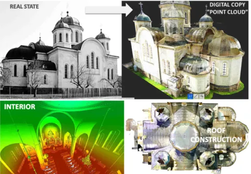
Pre-processing, the most important step in this part of this stage is the process of registration. With this process all individual raw scans are combining together and the result is one coordinate system, or as mentioned before the result of the laser survey is a very dense point cloud (Fig. 3), [1]. Of course the point cloud consists of a lot of redundant information like a surrounding buildings, trees, cars, people, equipment, road surface etc., which needs to be removed;
Fig. 3. From real state to point cloud, (Source: Authors)
Post-processing, the second stage of point cloud data management is post processing which is an operation to form a 3D model of objects based on point cloud [7].
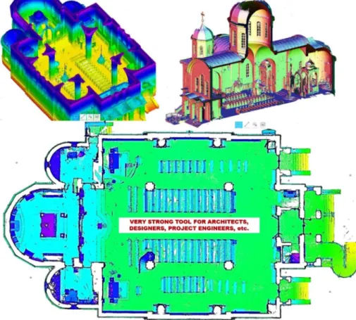
Looking Fig. 4 it can be seen that if an object from outdoor and from indoor too was captured in this case all geometry information from the building is known (for example,
thickens of walls, thickness of ceilings, etc.) in digital environment, and what is very important there is possibility to create a horizontal or vertical cutting plane anywhere.
Fig. 4. Different views of cutting planes from the point cloud, (Source: Authors)
With this ability it is possible to create from the point cloud the complete as-built documentation. The as-built documentation, meaning documentation of the existing state of structures is an essential input for architects, project managers, engineers, designers, or planners. Because the reality is transferred for example to the CAD software with everything that really exists, all other operations take place on a computer. With advanced laser scanning technology and the creation of real 3D model in the computer, the considerable financial costs associated with effective planning and constructing, as well as actual time will be saved.
4. When to use laser scanning in the BIM market
Since laser scanners capture reality with exceedingly high efficiency, they are primarily used in applications where this capability provides added value. In the BIM
market, these uses generally fall into two categories: renovations (Scan-to-BIM) and new construction (Scan-vs-BIM) [5], [14].
Renovations: (creating a geometry of BIM model from point cloud)
The building information model can be used in all stages of the lifecycle of the building project. One of these stages is also the stage of renovation. The stage of renovation is the most commonly used stage where it is possible to use the technology of Terrestrial Laser Scanning (TLS) for creating new as-built BIM model for the purpose of reconstruction or modernization of an existing building.
For renovations or additions to an existing structure, drawings are often out of date or simply said does not exist. This makes designing any type of renovation or addition difficult. The laser scanner locates whatever it sees and the site in time in its current form. This data then can be brought into BIM packages and used to develop extremely accurate existing condition drawings/modeling [5]. The process of creating a geometry of BIM model from point cloud data is often called Scan-to-BIM. In this process, recognizing and reconstructing objects from point cloud are very complex tasks due to the sizes of the point clouds and the vast quantities of information needed to describe the environment. For this reason current Scan-to-BIM techniques require significant manual operation [14]. The challenge here is to create a parametric 3D BIM model from the precise depiction of the real world, in the form of a point cloud [15]. Point cloud based modeling has become widely used in recent years in the engineering practice [16].
First it is necessary to transfer the original survey data into the required BIM system, for example, Autodesk Revit, Graphisoft ArchiCAD, etc. that are capable of importing and displaying large point clouds [15]. The choice of which software tool to use for modeling should depend upon the desired scope outcome [11]. There, it is then possible to use the point cloud as a modeling reference.
Point snapping allows the precise remodeling of the point cloud regions with 3D BIM elements (Fig. 5) [15].
BIM is about parametric modeling. Parametric modeling refers to the relationship between all elements in a project that enables the coordination and change management that the BIM software provides. For example, a door is a fixed dimension from an adjacent partition wall. If the wall moves, the door remains this relationship to the wall.
Other example, the floor or roof is connected to the exterior wall so that when the exterior wall is moved, the floor or roof remains connected. In this case, the parameter is one of association or connection [17].
The stage of the renovation includes a many times the laser survey of different types of the sacral historical buildings/constructions. These types of historical buildings often include constructions or part of structures that have irregular shapes or in other words the unique shape, as it can be seen in Fig. 5. These shapes cannot often be modeled using by standard object elements (for example, standard parametric wall or column) that are located in the BIM database. If, for example, the Revit library does not provide a desired detail object (for example, a certain type of wall),it is possible to create a new detail component family to meet your needs, as it can be seen in Fig. 5 again.
Fig. 5. Remodeling of the point cloud regions with 3D BIM elements, (Source: Authors)
The paramount wish on the software developed is doubtlessly for fully-automatic and flawless pattern recognition. The software should analyze the whole point cloud, locate all of the fittings, recognize their type and fit the position and parameter optimally onto the observed data. But a fully automated system requires the acceptance of the closed world assumption which means that everything what in the point cloud can be found must also be able to model in the BIM system [17].
New construction: (comparing the point cloud with the geometry of BIM model) Laser scanning can be deployed in many places in a new construction project to aid the BIM process. As construction progresses, laser scanning data can be used to compare the newly constructed work, against the as-designed model or drawings for quality assurance. If laser scanning is used throughout the entire construction project, the new facility will have as-built documentation from all the major milestones in the project [5]. Integrating TLS and BIM in Scan-vs-BIM processes can be beneficial for progress and quality control, and even 3D as-build BIM model delivery [14].
For example, scanning all components as they are installed can provide a time-lapse record with millimeter accuracy data on the pipes, structural steels, Mechanical Electrical and Plumbing (MEP) work progress control, creating a record of what is behind the walls, above the ceilings and under the floor slabs, tracking of temporary (e.g. scaffolds) or second (rebar in the concrete slabs throughout the building along with the actual installation date), quickly assess the slab flatness of concrete floors, easily calculate the extents of any areas that need to be adjusted and accurately determine the volume of material needed, dimensional quality control both on-site and during pre-
fabrication, etc. [5], [14]. One of the main constraints to the good performance of Scan- vs-BIM approaches for supporting the applications above (as-built/as-is BIM modeling, dimensional quality control, etc.) is the quality and completeness of the input TLS data [14].
This information can be compared to the design to verify that all components are installed in the correct place. If any errors are discovered, the design can be revised so that new components can be altered in the construction process instead of making costly changes onsite [5].
Case study - control of family house geometry using technology of terrestrial laser scanning
The purpose of this case study is to describe a simple principle of control the geometry of the family house using the technology of terrestrial laser scanning. This case study serves as an example and is divided into three phases.
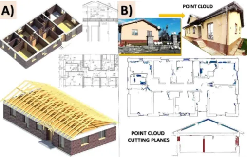
Phase A: For the purpose of the control, a simple geometry of the BIM model (in the software Autodesk Revit) was created from the existing project documentation as it can be seen in Fig. 6A.
Phase B: For the laser survey of the family house was used the laser scanner Faro Focus X130 and 12 reference spheres. The house was measured completely, that means, from the outdoor and from the indoor. The total scanning time was 8 hours. For data processing was used the software Faro Scene and Autodesk Recap and the total data processing time was 3 hours. The result of laser survey is shown in Fig. 6B.
Fig. 6. A) BIM model created from existing project documentation, B) Laser scanning of the family house for a purpose to check the geometry of the BIM model, (Source: Authors)
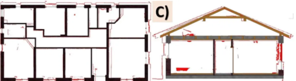
Phase C: In the final phase the point cloud was connected to the geometry of the BIM model in the software Autodesk Revit. The point cloud in this case represents the red color, as it can be seen in Fig. 7. The BIM model in this case represents the existing project documentation on the basis of which the house was to have been realized and the point cloud represents the real state of the family house. Based on this comparison it can be seen differences and deviations between the point cloud and the geometry of the BIM model. Based on these results it is possible to update or correct the geometry of the BIM model based on the point cloud where the point cloud serves as the accurate template for these corrections.
Fig. 7. C) Interconnection between the point cloud and geometry of the BIM model, (Source: Authors)
5. Conclusion
BIM methodology is increasingly penetrating into building design. It will also lead to an inevitable increase in the demand for BIM modeling in the existing building stock.
That raises the question, what is the most effective method of surveying existing buildings? Laser scanning appears to be the ideal solution and it has a variety of applications on construction projects ranging from new construction to renovations, and the captured data can be useful to the entire project team, including the architects and engineers, from project conception through project turnover. It allows the quick and precise high definition capture of 3D data. The accuracy made possible through the use of laser scanning is unparalleled by manual measurement and traditional field surveying techniques. Furthermore, human interpretation of field conditions impacts the accuracy of documentation due to the means and methods of capturing, as well as during the conversion of field measurements to digital models. While sometimes it’s quicker to use the old methods, rather than the laser scanner, the great advantage of scanning is its speed on site. It collects absolutely everything very quickly.
This paper offers an overview of the laser survey stages, processing of point cloud data and the possibility to integrate these data into the building information modeling workflow. At present, laser scanners can be divided into three categories and it;
terrestrial laser scanners, mobile and airborne laser scanners. This paper describes only the methodology of terrestrial laser scanning and its use in the BIM process. The main task of terrestrial laser scanning is to create new as-built documentation mainly for buildings where existing documentation is not accurate, is not actual or does not exist.
In the BIM workflow this process is known as Scan-to-BIM, that means, that based on the scan data is possible to create new and accurate geometry of the BIM model, e.g. for purpose of renovation of some exist building without project documentation. Laser scanning the existing conditions on renovations also allows to compare the as-built conditions with the as-planned design. This process is known as Scan-vs-BIM, that means, that based on the scan data is possible to compare the point cloud with exist geometry of BIM model. This comparison can be used either in reconstructions or in new construction. Scanning progressively during construction to compare with as- designed BIM models and drawings, provide archival records, and document critical milestones provides tremendous value throughout the construction process. Laser scanning helps lower contractor risks by ensuring as-built drawings are accurate and by exposing any inaccuracies early in the process, before they turn into change orders during construction.
Acknowledgements
The article presents a partial research result of project VEGA – 1/0828/17 ‘Research and application of knowledge-based systems for modeling cost and economic parameters in Building Information Modeling’.
The article presents a partial research result of project: CE II, ITMS: 26220120037, Excellent integrated research center of progressive building construction, material and technology.
The article presents a partial research result of project KEGA - 059TUKE-4/2017
‘Supporting the skills in use of BIM technology in a building life-cycle’.
References
[1] Bornaz L., Rinaudo F. Terrestrial laser scanning data processing, 2017, http://citeseerx.
ist.psu.edu/viewdoc/download?doi=10.1.1.434.5357&rep=rep1&type=pdf, (last visited 11 December 2017).
[2] Coşarcă C., Jocea A., Savu A. Analysis of error sources in terrestrial laser scanning, FIG Working Week 2012, Knowing to manage the territory, protect the environment, evaluate the cultural heritage, Rome, Italy, 6-10 May 2012,2011, https://www.fig.
net/resources/proceedings/fig_proceedings/fig2012/papers/ts07a/TS07A_alkan_6097.pdf, (last visited 11 December 2017).
[3] Nguyen T. T., Quang M. N., Xiu G. L., Yao Y. Z. 3D object model reconstruction based on laser scanning point cloud data, International Symposium on GeoInformatics for Spatial- Infrastructure Development in Earth and Allied Sciences (GIS-IDEAS), Ho Chi Minh City, Vietnam, 16-20 October 2012, https://www.researchgate.net/publication/306278163_3D_
object_model_reconstruction_based_on_laser_scanning_point_cloud_data, (last visited 13 December 2017).
[4] Hubert D., Akinci B., Tang P., Adan A., Okorn B., Xiong X. Using laser scanners for modeling and analysis in architecture, engineering, and construction, 44th Annual Conference on Information Sciences and Systems (CISS), Princeton, NJ, USA, 17-19 March 2010, Paper No. 5464818, http://ieeexplore.ieee.org/document/5464818/
?reload=true, (last visited 14 December 2017).
[5] Hayes C., Richie E. When to use laser scanning in building construction, A guide for general contractors, 2015, http://constructrealityxyz.com/test/ebook/LGS_AU_When%20to
%20Use%20Laser%20Scanning.pdf, (last visited 14 December 2017).
[6] Alkan R. M., Kardisiag G. Analysis of the accuracy of terrestrial laser scanning measurements, FIG Working Week 2012, Knowing to manage the territory, protect the environemnt, evaluate the cultural heritage, Rome, Italy, 6-10 May 2012, https://www.fig.net/resources/proceedings/fig_proceedings/fig2012/papers/ts07a/TS07A_al kan_6097.pdf, (last visited 15 December 2017).
[7] Aziz M. A., Idris K. M., Majid Z., Ariff M. F. M., Yusoff A. R., Luh L. C., Abbas M. A., Chong A. K. A study about terrestrial laser scanning for reconstruction of precast concrete to support classic assessment, International Conference on Geomatic and Geospatial Technology (GGT) 3-5 October 2016, Kuala Lumpur, Malaysia, The international Archives of the Photogrammetry, Remote Sensing and Spatial Information Sciences, Vol. XLII- 4/W1, 2016, http://www.int-arch-photogramm-remote-sens-spatial-inf-sci.net/XLII-4- W1/135/2016/isprs-archives-XLII-4-W1-135-2016.pdf, (last visited 18 December 2017).
[8] Antova G., Kunchev I., Mickrenska-Cherneva Ch. Point clouds in BIM, IOP Conf. Series:
Earth and Environmental Science, Vol. 44, 2016, Paper No. 042034,
[9] Gleason D. Lasers scanning for an integrated BIM, Lake Constance 5D Conference, Implementing 5D in the Construction Industry, Constance, Germany, 28-29 October 2013, https://www.tekla.com/de/trimble-5d/laser-scanning-for-bim.pdf, (last visited 19 December 2017).
[10] Berényi, A. Laser scanning in engineering survey - An application study, Pollack Periodica, Vol. 5, No. 2, 2010, pp. 39‒48.
[11] Bosche F., Turkan Y., Haas C. T., Haas R. Fusion 4D modeling and laser scanning for construction schedule control, http://cyberbuild.hw.ac.uk/publications/conference/Bosche- 2010-ARCOM.pdf, (last visited 19 December 2017).
[12] Scan to BIM procedure (Surface reconstruction), Advenser, 2017, https://www.pointcloud bimmodeling.com/scan-to-bim-procedure/, (last visited 20 December 2017).
[13] Kimpton G. R., Horne M., Heslop D. Terrestrial laser scanning and 3D imaging: Heritage case study - The Black Gate, Newcastle Upon Tyne, International Archives of Photogrammetry, Remote Sensing and Spatial Information Sciences, Vol. XXXVIII, Part 5, Commission V Symposium, Newcastle-upon-Tyne, UK, 22-24 June 2010, pp. 325‒330, http://nrl.northumbria.ac.uk/1277/, (last visited 20 December 2017).
[14] Biswas H. K. Planning for scanning in construction: Optimizing 3D laser scanning operations using building information modeling and a novel specification on surface scanning completeness, Heriot-Watt University, School of Energy, Geoscience, Infrastructure and Society, Dissertation work, May 2016, http://www.ros.hw.ac.uk/
bitstream/handle/10399/3155/BiswasHK_0616_egis.pdf?sequence=1&isAllowed=y, (last visited 20 December 2017).
[15] From point cloud to BIM, AEC Magazine, Building Information Modeling (BIM) Technology for Architecture, Engineering and Construction, 12 March 2015, http://aecmag.com/59-features/829-from-point-cloud-to-bim, (last visited 21 December 2017).
[16] Somogi A., Lovas T., Barsi Á. Comparison of spatial reconstruction software packages using DSLR images, Pollack Periodica, Vol. 12, No. 2, 2017, pp. 17‒27.
[17] About parametric modeling relationships, Autodesk, 29 March 2017, https://knowledge.autodesk.com/support/revit-products/getting-started/caas/CloudHelp/
cloudhelp/2016/ENU/Revit-GetStarted/files/GUID-71F2C8EE-2A90-4076-A6C7- 702082566DDF-htm.html, (last visited 22 December 2017).