Wojciech Burakowski1(B), Andrzej Beben1, Hans van den Berg2, Joost W. Bosman3, Gerhard Hasslinger4, Attila Kertesz5, Steven Latre6,
Rob van der Mei3, Tamas Pflanzner5, Patrick Gwydion Poullie7, Maciej Sosnowski1, Bart Spinnewyn6, and Burkhard Stiller7
1 Warsaw University of Technology, Warsaw, Poland {wojtek,abeben,m.sosnowski}@tele.pw.edu.pl
2 Netherlands Organisation for Applied Scientific Research, The Hague, Netherlands
j.l.vandenberg@tno.nl
3 Centrum Wiskunde & Informatica, Amsterdam, Netherlands {j.w.bosman,r.d.van.der.mei}@cwi.nl
4 Deutsche Telekom AG, Bonn, Germany Gerhard.Hasslinger@telekom.de
5 University of Szeged, Szeged, Hungary {keratt,tamas.pflanzner}@inf.u-szeged.hu
6 University of Antwerp - iMINDS, Antwerp, Belgium {steven.latre,bart.spinnewyn}@uantwerpen.be
7 University of Z¨urich - CSG@IfI, Z¨urich, Switzerland {poullie,stiller}@ifi.uzh.ch
Abstract. The chapter summarizes activities of COST IC1304 ACROSS European Project corresponding to traffic management for Cloud Federation (CF). In particular, we provide a survey of CF archi- tectures and standardization activities. We present comprehensive multi- level model for traffic management in CF that consists of five levels: Level 5 - Strategies for building CF, Level 4 - Network for CF, Level 3 - Service specification and provision, Level 2 - Service composition and orchestra- tion, and Level 1 - Task service in cloud resources. For each level we propose specific methods and algorithms. The effectiveness of these solu- tions were verified by simulation and analytical methods. Finally, we also describe specialized simulator for testing CF solution in IoT environment.
Keywords: Cloud federation
·
Traffic management Multi-layer model·
Service provision·
Service composition1 Introduction
Cloud Federation (CF) extends the concept of cloud computing systems by merg- ing a number of clouds into one system. Thanks to this, CF has a potentiality to offer better service to the clients than it can be done by a separated cloud.
This can happen since CF has more resources and may offer wider scope of ser- vices. On the other hand, the management of CF is more complex comparing to
c The Author(s) 2018
I. Ganchev et al. (Eds.): Autonomous Control for a Reliable Internet of Services, LNCS 10768, pp. 269–312, 2018.
https://doi.org/10.1007/978-3-319-90415-3_11
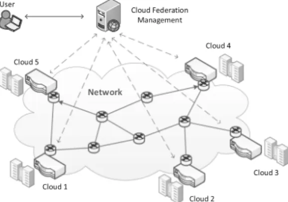
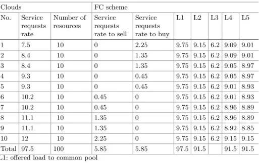
this which is required for a standalone cloud. So, the effective management of resources and services in CF is the key point for getting additional profit from such system. CF is the system composing of a number of clouds connected by a network, as it is illustrated on Fig.1. The main concept of CF is to operate as one computing system with resources distributed among particular clouds.
Fig. 1.Exemplary CF consisting of 5 clouds connected by network.
In this chapter we present a multi-level model for traffic management in CF.
Each level deals with specific class of algorithms, which should together provide satisfactory service of the clients, while maintaining optimal resource utilization.
The structure of the chapter is the following. In Sect.2 we present dis- cussed CF architectures and the current state of standardization. The proposed multi-level model for traffic management in CF is presented in Sect.3. Section4 describes a simulation tool for analyzing performance of CF in Internet of Things (IoT) environment. Finally, Sect.5 summarizes the chapter.
2 Cloud Federation Architectures
2.1 Cloud Architectural Views
In general CF is envisaged as a distributed, heterogeneous environment con- sisting of various cloud infrastructures by aggregating different Infrastructure as a Service (IaaS) provider capabilities coming from possibly both the com- mercial and academic area. Nowadays, cloud providers operate geographically diverse data centers as user demands like disaster recovery and multi-site back- ups became widespread. These techniques are also used to avoid provider lock-in issues for users that frequently utilize multiple clouds. Various research communi- ties and standardization bodies defined architectural categories of infrastructure clouds. A current EU project on “Scalable and secure infrastructures for cloud operations” (SSICLOPS,www.ssiclops.eu) focuses on techniques for the manage- ment of federated private cloud infrastructures, in particular cloud networking
techniques within software-defined data centers and across wide-area networks.
The scope of the SSICLOPS project includes high cloud computing workloads e.g. within the CERN computing cloud (home.cern/about/computing) as well as cloud applications for securing web access under challenging demands for low delay. An expert group set up by the European Commission published their view on Cloud Computing in [1]. These reports categorize cloud architectures into five groups.
– Private Clouds consist of resources managed by an infrastructure provider that are typically owned or leased by an enterprise from a service provider.
Usually, services with cloud-enhanced features are offered, therefore this group includes Software as a Service (SaaS) solutions like eBay.
– Public Clouds offer their services to users outside of the company and may use cloud functionality from other providers. In this solution, enterprises can outsource their services to such cloud providers mainly for cost reduction.
Examples of these providers are Amazon or Google Apps.
– Hybrid Clouds consist of both private and public cloud infrastructures to achieve a higher level of cost reduction through outsourcing by maintaining the desired degree of control (e.g., sensitive data may be handled in private clouds). The report states that hybrid clouds are rarely used at the moment.
– In Community Clouds, different entities contribute with their (usually small) infrastructure to build up an aggregated private or public cloud. Smaller enter- prises may benefit from such infrastructures, and a solution is provided by Zimory.
– Finally, Special Purpose Clouds provide more specialized functionalities with additional, domain specific methods, such as the distributed document man- agement by Google’s App Engine. This group is an extension or a specializa- tion of the previous cloud categories.
The third category called hybrid clouds are also referred as cloud federations in the literature. Many research groups tried to grasp the essence of federa- tion formation. In general, cloud federation refers to a mesh of cloud providers that are interconnected based on open standards to provide a universal decen- tralized computing environment where everything is driven by constraints and agreements in a ubiquitous, multi-provider infrastructure. Until now, the cloud ecosystem has been characterized by the steady rising of hundreds of indepen- dent and heterogeneous cloud providers, managed by private subjects, which offer various services to their clients.
Buyya et al. [2] envisioned Cloud Computing as the fifth utility by satisfy- ing the computing needs of everyday life. They emphasized and introduced a market-oriented cloud architecture, then discussed how global cloud exchanges could take place in the future. They further extended this vision suggesting a federation oriented, just in time, opportunistic and scalable application services provisioning environment called InterCloud. They envision utility oriented fed- erated IaaS systems that are able to predict application service behavior for intelligent down and up-scaling infrastructures. They list the research issues of
flexible service to resource mapping, user and resource centric Quality of Service (QoS) optimization, integration with in-house systems of enterprises, scalable monitoring of system components. They present a market-oriented approach to offer InterClouds including cloud exchanges and brokers that bring together pro- ducers and consumers. Producers are offering domain specific enterprise Clouds that are connected and managed within the federation with their Cloud Coor- dinator component.
Celesti et al. [3] proposed an approach for the federation establishment con- sidering generic cloud architectures according to a three-phase model, represent- ing an architectural solution for federation by means of a Cross-Cloud Federation Manager, a software component in charge of executing the three main function- alities required for a federation. In particular, the component explicitly manages:
1. the discovery phase in which information about other clouds are received and sent,
2. the match-making phase performing the best choice of the provider according to some utility measure and
3. the authentication phase creating a secure channel between the federated clouds. These concepts can be extended taking into account green policies applied in federated scenarios.
Bernstein et al. [4] define two use case scenarios that exemplify the problems of multi-cloud systems like
1. Virtual Machines (VM) mobility where they identify the networking, the spe- cific cloud VM management interfaces and the lack of mobility interfaces as the three major obstacles and
2. storage interoperability and federation scenario in which storage provider replication policies are subject to change when a cloud provider initiates sub- contracting. They offer interoperability solutions only for low-level functional- ity of the clouds that are not focused on recent user demands but on solutions for IaaS system operators.
In the Federated Cloud Management solution [5], interoperability is achieved by high-level brokering instead of bilateral resource renting. Albeit this does not mean that different IaaS providers may not share or rent resources, but if they do so, it is transparent to their higher level management. Such a federation can be enabled without applying additional software stack for providing low- level management interfaces. The logic of federated management is moved to higher levels, and there is no need for adapting interoperability standards by the participating infrastructure providers, which is usually a restriction that some industrial providers are reluctant to undertake.
2.2 Standardization for Cloud Federation
Standardization related to clouds, cloud interoperability and federation has been conducted by the ITU (International Telecommunication Union) [6],
IETF (Internet Engineering Task Force) [7], NIST (National Institute of Stan- dards and Technology) [8] and IEEE (Institute of Electrical and Electronics Engineers) [9]. In 2014, the ITU released standard documents on the vocabu- lary, a reference architecture and a framework of inter-cloud computing. The latter provides an overview, functional requirements and refers to a number of use cases. The overview distinguishes between:
– Inter-cloud Peering: between a primary and secondary CSP (i.e. Cloud Service Provider), where cloud services are provided by the primary CSP who estab- lishes APIs (application programming interfaces) in order to utilize services and resources of the secondary CSP,
– Inter-cloud Intermediary: as an extension of inter-cloud peering including a set of secondary CSPs, each with a bilateral interface for support of the primary CSP which offers all services provided by the interconnected clouds, and – Inter-cloud Federation: which is based on a set of peer CSPs interconnected
by APIs as a distributed system without a primary CSP with services being provided by several CSPs. For each service, the inter-cloud federation may act as an inter-cloud intermediary with a primary CSP responsible for the service.
The user population may also be subdivided and attributed to several CSPs.
The main functional requirements to set up and operate a cloud federation system are:
– Networking and communication between the CSPs, – Service level agreement (SLA) and policy negotiations, – Resource provisioning and discovery mechanisms,
– Resource selection, monitoring and performance estimation mechanisms, – Cloud service switch over between CSPs.
Finally, the ITU [6] takes a number of use cases into account to be addressed by could interconnection and federation approaches:
– Performance guarantee against an abrupt increase in load (offloading), – Performance guarantee regarding delay (optimization for user location), – Guaranteed availability in the event of a disaster or large-scale failure, – Service continuity (in the case of service termination of the original CSP),
service operation enhancement and broadening service variety,
– Expansion and distribution of cloud storage, media and virtual data center, – Market transactions in inter-cloud intermediary pattern and cloud service
rebranding.
The standardization on cloud federation has many aspects in common with the interconnection of content delivery networks (CDN). A CDN is an infras- tructure of servers operating on application layers, arranged for the efficient distribution and delivery of digital content mostly for downloads, software updates and video streaming. The CDN interconnection (CDNI) working group
of the IETF provided informational RFC standard documents on the prob- lem statement, framework, requirements and use cases for CDN interconnec- tion in a first phase until 2014. Meanwhile specifications on interfaces between upstream/downstream CDNs including redirection of users between CDNs have been issued in the proposed standards track [7]. CDNs can be considered as a special case of clouds with the main propose of distributing or streaming large data volumes within a broader service portfolio of cloud computing applications.
The underlying distributed CDN architecture is also useful for large clouds and cloud federations for improving the system scalability and performance. This is reflected in a collection of CDNI use cases which are outlined in RFC 6770 [7]
in the areas of:
– footprint extension, – offloading,
– resilience enhancement,
– capability enhancements with regard to technology, QoS/QoE support, the service portfolio and interoperability.
The CDNI concept is foreseen as a basis for CDN federations, where a fed- eration of peer CDN systems is directly supported by CDNI. A CDN exchange or broker approach is not included but can be build on top of core CDNI mech- anisms.
In 2013, NIST [8] published a cloud computing standards roadmap includ- ing basic definitions, use cases and an overview on standards with focus on cloud/grid computing. Gaps are identified with conclusions on priorities for ongo- ing standardization work. However, a recently started standards activity by the IEEE [9] towards intercloud interoperability and federation is still motivated by today’s landscape of independent and incompatible cloud offerings in proprietary as well as open access architectures.
3 Multi-level Model for Traffic Management in Cloud Federation
Developing of efficient traffic engineering methods for Cloud Federation is essen- tial in order to offer services to the clients on appropriate quality level while maintaining high utilization of resources. These methods deal with such issues as distribution of resources in CF, designing of network connecting particular clouds, service provision, handling service requests coming from clients and man- aging virtual resource environment. The proposed traffic management model for CF consists of 5 levels, as it is depicted on Fig.2. Below we shortly discuss objectives of each level of the model.
Level 5: This is the highest level of the model which deals with the rules for merging particular clouds into the form of CF. The addressed issue is e.g.
amount of resources which would be delegated by particular clouds to CF. We assume that the main reason for constituting federation is getting more profit
Fig. 2.Traffic management model for Cloud Federation
comparing to the situation when particular clouds work alone. So, this level deals with the conditions when CF can be attractive solution for cloud owners even if particular clouds differ in their capabilities, e.g. in amount of resources, client population and service request rate submitted by them.
Level 4: This level deals with design of the CF network for connecting par- ticular clouds. Such network should be of adequate quality and, if it is possible, its transfer capabilities should be controlled by the CF network manager. The addressed issues are: required link capacities between particular clouds and effec- tive utilization of network resources (transmission links). We assume that net- work capabilities should provide adequate quality of the offered by CF services even when resources allocated for a given service (e.g. virtual machines) come from different clouds. Effective designing of the network in question is especially important when CF uses network provided by a network operator based on SLA (Service Level Agreement) and as a consequence it has limited possibilities to control network. Currently such solution is a common practice.
Level 3: This level is responsible for handling requests corresponding to ser- vice installation in CF. The installation of new service requires: (1) specification of the service and (2) provision of the service. Specification of the service is pro- vided in the form of definition of appropriate task sequence that is executed in CF when a client asks for execution of this service. Furthermore, provision of
the service corresponds to allocation of resources when particular tasks can be executed.
Level 2: This level deals with service composition and orchestration pro- cesses. So, the earlier specified sequence of tasks should be executed in response to handle service requests. Service composition time should meet user quality expectations corresponding to the requested service.
Level 1: The last and the lowest level deals with task execution in cloud resources in the case when more than one task is delegated at the same time to be served by a given resource. So, appropriate scheduling mechanisms should be applied in order to provide e.g. fairness for tasks execution. In addition, impor- tant issue is to understand dependencies between different types of resources in virtualized cloud environment.
3.1 Level 5: Strategy for Cloud Resource Distribution in Federation 3.1.1 Motivation and State of the Art
Cloud Federation is the system that is built on the top of a number of clouds.
Such system should provide some additional profits for each cloud owner in comparison to stand-alone cloud. In this section we focus on strategies, in which way clouds can make federation to get maximum profit assuming that it is equally shared among cloud owners.
Unfortunately, there are not too many positions dealing with discussed prob- lem. For instance in [10] the authors consider effectiveness of different federation schemes using the M/M/1 queueing system to model cloud. They assume that profit get from a task execution depends on the waiting time (showing received QoS) of this task. Furthermore, they consider scenarios when the profit is max- imized from the perspective of the whole CF, and scenarios when each cloud maximizes its profit. Another approach is presented in [11], where the author applied game theory to analyze the selfish behavior of cloud owner selling unused resources depending on uncertain load conditions.
3.1.2 Proposed Model
In the presented approach we assume that capacities of each cloud are charac- terized in terms of number of resources and service request rate. Furthermore, for the sake of simplicity, it is assumed that both types of resources and exe- cuted services are the same in each cloud. In addition, execution of each service is performed by single resource only. Finally, we will model each cloud by well- known loss queueing system M/M/c/c (e.g. [12]), where c denotes number of identical cloud resources, arrival service request rate follows Poisson distribu- tion with parameterλ, service time distribution is done by negative exponential distribution with the rate 1/h(his the mean service time). The performances of cloud system are measured by: (1) Ploss, which denotes the loss rate due to lack of available resources at the moment of service request arrival, and (2) Acarried=λh(1−Ploss), which denotes traffic carried by the cloud, that corre- sponds directly to the resource utilization ratio.
Now, let us search for the appropriate scheme for building CF system. For this purpose, let us consider a number, say N, of clouds that intend to build CF where the i-th cloud (i = 1, ..., N) is characterized by two parameters (λi
and ci). In addition, the mean service times of service execution are the same in each cloud h1 = h2 = ... = hN = h. Subsequently we assume that h = 1, and as a consequence offered load A = λh will be denoted as A = λ. Next, the assumed objective function for comparing the discussed schemes for CF is to maximize profit coming from resource utilization delegated from each cloud to CF. Furthermore, the profit is equally shared among clouds participating in CF. Such approach looks to be reasonable (at least as the first approach) since otherwise in CF we should take into account requests coming from a given cloud and which resource (from each cloud) was chosen to serve the request.
We consider three schemes:
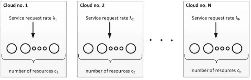
– Scheme no. 1 (see Fig.3): this is the reference scheme when the clouds work alone, denoted by SC.
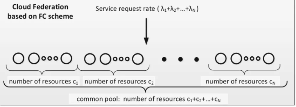
– Scheme no. 2 (see Fig.4): this scheme is named as full federation and assumes that all clouds dedicate all theirs resources and clients to the CF system. This scheme we denote as FC.
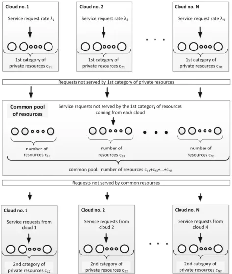
– Scheme no. 3 (see Fig.5): for this scheme we assume that each cloud can delegate to CF only a part of its resources as well as a part of service requests coming from its clients. This scheme we name as PCF (Partial CF).
First, let us compare the performances of schemes SC and FC in terms of resource utilization ratio and service request loss rate. The first observation is that FC scheme will have lower loss probabilities as well as better resource utilization ratio due to larger number of resources. But the open question is in which way to share profit gained from FC scheme when the clouds are of different capabilities? Table1shows exemplary results for the case, when the profit, which is consequence of better resources utilization, is shared equally among clouds.
The results from Table1show that, as it was expected, FC scheme assures less service request loss rate and better resource utilization ratio for most of clouds (except cloud no. 1 that is under loaded). Note, that if we share the profit equally, the clouds with smaller service requests rate can receive more profit from FC
Fig. 3.Scenario with clouds working in separate way
Fig. 4.Scenario with clouds creating Cloud Federation based on full federation scheme
scheme comparing to the SC scheme while the clouds with higher service request rate get less profit comparing to the SC scheme. So, one can conclude that FC scheme is optimal solution when the capabilities of the clouds are similar but if they differ essentially then this scheme simply fails.
Scheme no. 3 mitigates the drawbacks of the schemes no. 1 and no. 2. As it was above stated, in this scheme we assume that each cloud can delegate to CF only a part of its resources as well as a part of service request rate submitted by its clients. The main assumptions for PFC scheme are the following:
Table 1.Exemplary results comparing SC and FC schemes in terms of loss rate and resource utilization parameters. Number of cloudsN = 5, values ofλ:λ1= 0.2, λ2 = 0.4, λ3 = 0.6, λ4 = 0.8, the same mean service times h1 = h2 = h3 =h4 =h5 = 1, Number of resources in each cloud:c1=c2=c3=c4 =c5= 10.
Cloud characteristics SC scheme FC scheme No. Service
requests rate
Number of resources
Resource utilization
Loss rate [%]
Resource utilization
Loss rate[%]
1 2 10 0.2 <0.01 0.6 0.02
2 4 10 0.398 0.54 0.6 0.02
3 6 10 0.575 4.3 0.6 0.02
4 8 10 0.703 12 0.6 0.02
5 10 10 0.786 21 0.6 0.02
1. we split the resources belonging to the i-th cloud (i= 1, ..., N), sayci, into 2 main subsets:
– set of private resources that are delegated to handle only service requests coming from thei-th cloud clients
– set of resources dedicated to Cloud Federation for handling service requests coming from all clouds creating Cloud Federation, denoted asci3
2. we again split the private resources into two categories:
– belonging to the 1st category, denoted asci1, which are dedicated as the first choice to handle service requests coming from thei-th cloud clients – belonging to the 2nd category, denoted as ci2, which are dedicated to
handle service requests coming from the i-th cloud clients that were not served by resources from 1st category as well as from common pool since all these resources were occupied.
The following relationship holds:
ci=ci1+ci2+ci3, fori= 1, ..., N. (1) The handling of service requests in PFC scheme is shown on Fig.5. The service requests from clients belonging e.g. to cloud no. i (i = 1, ..., N) are submitted as the first choice to be handled by private resources belonging to the 1st category. In the case, when these resources are currently occupied, then as the second choice are the resources belonging to common pool. The number of common pool resources equals (c13+c23+...+cN3). If again these resources are currently occupied then as the final choice are the resources belonging to the 2nd category of private resources of the considered cloud. The service requests are finally lost if also no available resources in this pool.
Next, we show in which way we count the resources belonging to particular clouds in order to get maximum profit (equally shared between the cloud owners).
We stress that the following conditions should be satisfied for designing size of the common pool:
Condition 1: service request rate (offered load) submitted by particular clouds to the common pool should be the same. It means that
Ploss1(λ1, c11)λ1=Ploss2(λ2, c21)λ2=...=PlossN(λN, cN1)λN (2) where the value of Ploss(λi, ci1) we calculate from the analysis of the system M/M/n/nby using Erlang formula:
Plossi(λi, ci1) =
λci1i ci1!
ci1
j=0λji j!
Note that we only require that mean traffic load submitted from each cloud to common pool should be the same. Let us note, that the service request arrival processes from each cloud submitted to this pool are generally different. It is due to the fact that these requests were not served by 1st category of private resources and as a consequence they are not still Poissonian.
Condition 2: the number of resources dedicated from each cloud to the com- mon pool should be the same
c13=c23=...=cN3.
Fig. 5.Handling of service requests in PFC scheme.
Finally, the algorithm for calculating resource distribution for each cloud is the following:
Step 1: to orderλi (i= 1, ..., N) values from minimum value to maximum.
Let thek-th cloud has minimum value ofλ.
Step 2: to calculate (using Formula2) for each cloud the values of the num- ber of resources delegated to category 1 of private resources, ci1 (i = 1, ..., N) assuming thatck1= 0.
Step 3: to choose the minimum value from set of (ci−ci1) (i= 1, ..., N) and to state that each cloud should delegate this number of resources to the common pool. Let us note that if for the i-th cloud the value of (ci−ci1) ≤0 then no
common pool can be set and, as a consequence, not conditions are satisfied for Cloud Federation.
Step 4: to calculate from the Formula1the number of 2nd category of private resources ci2 (i= 1, ..., N) for each cloud.
3.1.3 Exemplary Results
Now we present some exemplary numerical results showing performances of the described schemes. The first observation is that when the size of common pool grows the profit we can get from Cloud Federation also grows.
Example: In this example we have 10 clouds that differ in service request rates while the number of resources in each cloud is the same and is equal to 10. Table2 presents the numerical results corresponding to traffic conditions, number of resources and performances of the systems build under SC and PFC schemes. The required amount of resources belonging to particular categories were calculated from the above described algorithm.
Table2 says that thanks to the PFC scheme we extend the volume of served traffic from 76,95 up to 84,50 (about 10%). The next step to increase Cloud Federation performances is to apply FC scheme instead of PFC scheme.
Table 2.Numerical results showing comparison between SC and PFC schemes.
Clouds SC scheme PFC scheme
No. Service requests rate
Number of resources
Load served by cloud
Loss rate [%]
L1 L2 L3 L4 L5 L6 L7 L8 L9 L10
1 7.5 10 6.75 10 7.50 0 5 5 0.00 2.34 4.82 7.16 3.5 0.41 2 8.4 10 7.22 14 7.50 1 4 5 0.89 2.10 4.82 7.82 6.3 0.60 3 8.4 10 7.22 14 7.50 1 4 5 0.89 2.10 4.82 7.82 6.3 0.60 4 9.3 10 7.61 18 7.50 2 3 5 1.79 1.75 4.82 8.35 10 0.74 5 9.3 10 7.61 18 7.50 2 3 5 1.79 1.75 4.82 8.35 10 0.74 6 10.2 10 7.91 22 7.50 3 2 5 2.69 1.26 4.82 8.77 14 0.86 7 10.2 10 7.91 22 7.50 3 2 5 2.69 1.26 4.82 8.77 14 0.86 8 11.1 10 8.17 26 7.50 4 1 5 3.58 0.68 4.82 9.08 19 0.91 9 11.1 10 8.17 26 7.50 4 1 5 3.58 0.68 4.82 9.08 19 0.91 10 12 10 8.38 30 7.50 5 0 5 4.49 0.00 4.82 9.31 23 0.92 Total 97.5 100 76.95 75 25 25 50 22.39 13.91 48.2 84.50 7.55 L1: offered load to common pool
L2: number of the 1st category of private resources L3: number of the 2nd category of private resources L4: number of resources delegated to common pool L5: load served by the 1st category of private resources L6: load served by the 2nd category of private resources L7: load served by common pool of resources
L8: total load served by clouds L9: loss rate [%]
L10: load served gain comparing to SC scheme
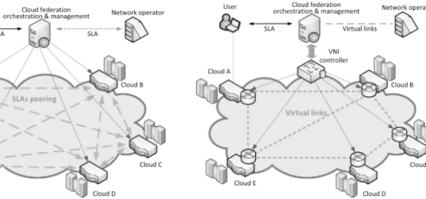
Unfortunately, it is not possible to be done in a straightforward way. It needs a moving of resources or service request rates between particular clouds. Table3 presents moving of service request rates in the considered example to make trans- formation from PFC scheme into the form of FC scheme. For instance, cloud no.
1 should buy value of service request rate of 2.25 while cloud no. 10 should sell value of service request rate also of 2.25. Finally, after buying/selling process, one can observe that the profit gained from FC scheme is greater than the profit we have got from PFC scheme and now is equal to 91.50 (19% comparing to SC scheme and 8% comparing to PFC scheme).
Concluding, the presented approach for modeling different cloud federation schemes as FC and PFC could be only applied for setting preliminary rules for establishing CF. Anyway, it appears that in some cases by using simple FC scheme we may expect the problem with sharing the profit among CF owners.
More precisely, some cloud owners may lost or extend their profits comparing to the case when their clouds work alone. Of course, more detailed model of CF is strongly required that also takes into account such characteristics as types of offered services, prices of resources, charging, control of service requests etc.
Table 3.Example showing system transformation into FC scheme.
Clouds FC scheme
No. Service requests rate
Number of resources
Service requests rate to sell
Service requests rate to buy
L1 L2 L3 L4 L5
1 7.5 10 0 2.25 9.75 9.15 6.2 9.09 9.01
2 8.4 10 0 1.35 9.75 9.15 6.2 9.09 9.01
3 8.4 10 0 1.35 9.75 9.15 6.2 9.05 8.97
4 9.3 10 0 0.45 9.75 9.15 6.2 9.05 8.97
5 9.3 10 0 0.45 9.75 9.15 6.2 9.01 8.93
6 10.2 10 0.45 0 9.75 9.15 6.2 9.01 8.93
7 10.2 10 0.45 0 9.75 9.15 6.2 8.96 8.89
8 11.1 10 1.35 0 9.75 9.15 6.2 8.96 8.89
9 11.1 10 1.35 0 9.75 9.15 6.2 8.92 8.85
10 12 10 2.25 0 9.75 9.15 6.2 9.15 9.15
Total 97.5 100 5.85 5.85 97.5 91.5 91.5 91.5
L1: offered load to common pool
L2: load served by common pool of resources L3: loss rate [%]
L4: load served gain comparing to PFC scheme L5: load served gain comparing to SC scheme
3.2 Level 4: Network for Cloud Federation 3.2.1 Motivation and State of the Art
The services offered by CF use resources provided by multiple clouds with dif- ferent location of data centers. Therefore, CF requires an efficient, reliable and secure inter-cloud communication infrastructure. This infrastructure is espe- cially important for mission critical and interactive services that have strict QoS requirements. Currently, CF commonly exploits the Internet for inter-cloud communication, e.g. CONTRAIL [13]. Although this approach may be suffi- cient for non-real time services, i.e., distributed file storage or data backups, it inhibits deploying more demanding services like augmented or virtual real- ity, video conferencing, on-line gaming, real-time data processing in distributed databases or live video streaming. The commonly used approach for ensuring required QoS level is to exploit SLAs between clouds participating in CF. These SLAs are established on demand during the service provisioning process (see Level 3 of the model in Fig.2) and use network resources coming from network providers. However, independently established SLAs lead to inefficient utilization of network resources, suffer scalability concerns and increase operating expen- ditures (OPEX) costs paid by CF. These negative effects become critical for large CFs with many participants as well as for large cloud providers offer- ing plethora of services. For example, the recent experiences of Google cloud point out that using independent SLAs between data centers is ineffective [14].
Therefore, Google creates their own communication infrastructure that can be optimized and dynamically reconfigured following demands of currently offered services, planned maintenance operations as well as restoration actions taken to overcome failures.
3.2.2 Proposed Solution
The proposed approach for CF is to create, manage and maintain a Virtual Net- work Infrastructure (VNI), which provides communication services tailored for inter-cloud communication. The VNI is shared among all clouds participating in CF and is managed by CF orchestration and management system. Actually, VNI constitutes a new “service component” that is orchestrated during service provi- sioning process and is used in service composition process. The key advantages of VNI are the following:
1. The common orchestration of cloud and VNI resources enables optimization of service provisioning by considering network capabilities. In particular, CF can benefit from advanced traffic engineering algorithms taking into account knowledge about service demands and VNI capabilities, including QoS guar- antees and available network resources. The objective function of designed algorithms may cover efficient load balancing or maximization and fair share of the CF revenue.
2. New communication facilities tailored for cloud services:
– The cloud services significantly differ in QoS requirements, e.g. interac- tive services are delay sensitive, while video on demand or big data storage
demands more bandwidth. Therefore, VNI should differentiate packet ser- vice and provide QoS guaranties following user’s requirements. The key challenge is to design a set of Classes of Services (CoS) adequate for han- dling traffic carried by federation. These CoSs are considered in the service orchestration process.
– The VNI should offer multi-path communication facilities that support multicast connections, multi-side backups and makes effective communi- cation for multi-tenancy scenarios. The key challenge is developing a scal- able routing and forwarding mechanisms able to support large number of multi-side communications.
The VNI is created following the Network as a Service (NaaS) paradigm based on resources provided by clouds participating in CF. Each cloud should provide: (1) virtual network node, which is used to send, receive or transit packets directed to or coming from other clouds, and (2) a number of virtual links estab- lished between peering clouds. These links are created based on SLAs agreed with network provider(s). The VNI exploits advantages of the Software Defined Networking (SDN) concept supported by network virtualization techniques. It makes feasible separation of network control functions from underlying physical network infrastructure. In our approach, CF defines its own traffic control and management functions that operate on an abstract model of VNI. The manage- ment focuses on adaptation of VNI topology, provisioning of resources allocated to virtual nodes and links, traffic engineering, and costs optimization. On the other hand, this VNI model is used during the service composition phase for dynamic resource allocation, load balancing, cost optimization, and other short time scale operations. Finally, decisions taken by VNI control functions on the abstract VNI model are translated into configuration commands specific for par- ticular virtual node.
Fig. 6.Two reference network scenarios considered for CF.
Figure6 shows the reference network scenarios considered for CF. Figure6a presents the scenario where CF exploits only direct communication between peering clouds. In this scenario, the role of CF orchestration and management is limited to dynamic updates of SLAs between peering clouds. Figure6b presents scenario where CF creates a VNI using virtual nodes provided by clouds and virtual links provided by network operators. The CF orchestration and man- agement process uses a VNI controller to setup/release flows, perform traffic engineering as well as maintain VNI (update of VNI topology, provisioning of virtual links).
The Control Algorithm for VNI. The VNI is controlled and managed by a specialized CF network application running on the VNI controller. This applica- tion is responsible for handling flow setup and release requests received from the CF orchestration and management process as well as for performing commonly recognized network management functions related to configuration, provisioning and maintenance of VNI. The flow setup requires a specialized control algorithm, which decides about acceptance or rejection of incoming flow request. Admis- sion decision is taken based on traffic descriptor, requested class of service, and information about available resources on routing paths between source and des- tination. In order to efficiently exploit network resources, CF uses multi-path routing that allows allocating bandwidth between any pair of network nodes up to the available capacity of the minimum cut of the VNI network graph.
Thanks to a logically centralized VNI architecture, CF may exploit different multi-path routing algorithms, e.g. [15,16]. We propose a new k-shortest path algorithm which considers multi-criteria constraints during calculation of alter- native k-shortest paths to meet QoS objectives of classes of services offered in CF.
We model VNI as a directed graphG(N, E), whereNrepresents the set of virtual nodes provided by particular cloud, while E is the set of virtual links between peering clouds. Each link u → v, u, v ∈ N, u → v ∈ E, is characterized by a m−dimensional vector of non-negative link weightsw(u→v) = [w1, w2, . . . , wm] which relates to QoS requirements of services offered by CF. Any path p established between two nodes is characterized by a vector of path weights w(p) = [w1(p), w2(p), . . . , wm(p)], where wi(p) is calculated as a concatenation of link weights wi of each link belonging to the path p. The proposed multi- criteria, k-shortest path routing algorithm finds a set of Pareto optimum paths, f ∈F, between each pair of source to destination nodes. A given path is Pareto optimum if its path weights satisfy constraints:wi(f)< li, i= 1, . . . , m, whereL is the vector of assumed constraints L= [l1, l2, . . . , lm] and it is non-dominated within the scope of the considered objective functions. Note that proposed multi- criteria, k-shortest path routing algorithm runs off-line as a sub-process in CF network application. It is invoked in response to any changes in the VNI topology corresponding to: instantiation or release of a virtual link or a node, detection of any link or node failures as well as to update of SLA agreements.
The VNI control algorithm is invoked when a flow request arrives from the CF orchestration process. The algorithm is responsible for: (1) selection of a subset of feasible alternative routing paths which satisfy QoS requirements of
the requested flow. Notice, that bandwidth requested in the traffic descriptor may be satisfied by a number of alternative path assuming flow splitting among them, (2) allocation of the flow to selected feasible alternative routing paths, and (3) configuration of flow tables in virtual nodes on the selected path(s).
The main objective of the proposed VNI control algorithm is to maximize the number of requests that are served with the success. This goal is achieved through smart allocation algorithm which efficiently use network resources. Remark, that flow allocation problem belongs to the NP-complete problems. The allocation algorithm has to take decision in a relatively short time (of second order) to not exceed tolerable request processing time. This limitation opt for using heuristic algorithm that find feasible solution in a reasonable time, although selected solution may not be the optimal one.
The proposed VNI control algorithm performs the following steps:
1. Create a decision space.In this step the algorithm creates a subset of feasi- ble alternative paths that meet QoS requirements from the set of k-shortest routing paths. The algorithm matches QoS requirements with path weights w(p). Then, it checks if selected subset of feasible alternative paths can meet bandwidth requirements, i.e. if the sum of available bandwidth on disjointed paths is greater than requested bandwidth. Finally, the algorithm returns the subset of feasible paths if the request is accepted or returns empty set ∅, which results in flow rejection.
2. Allocate flow in VNI.In this step, the algorithm allocates flow into previously selected subset of feasible paths. The allocation may address different objec- tives, as e.g.load balancing, keeping the flow on a single path, etc.depending on the CF strategy and policies. In the proposed algorithm, we allocate the requested flow on the shortest paths, using as much as possible limited num- ber of alternative paths. So, we first try to allocate the flow on the latest loaded shortest path. If there is not enough bandwidth to satisfy demand, we divide the flow over other alternative paths following the load balancing principles. If we still need more bandwidth to satisfy the request, we consider longer alternative paths in consecutive steps. The process finishes when the requested bandwidth is allocated.
3. Configure flow tables.In the final step, the VNI control algorithm configures allocated paths using the abstract model of VNI maintained in the SDN controller. The actual configuration is performed by the management system of particular cloud using e.g. Open Flow protocol, net conf or other.
3.2.3 Performance Evaluation
The experiments focus on performance evaluation of the proposed VNI control algorithm. They are performed assuming a model of CF comprising n clouds offering the same set of services. A CF network assumes a full mesh topology where peering clouds are connected by virtual links. In this model the number of degree of freedom in selecting alternative paths is relatively large. Our experi- ments are performed by simulation. We simulate flow request arrival process and
(a) balanced load (b) unbalanced load
Fig. 7.Blocking probabilities of flow requests served by VNI using different number of alternative paths.
analyze the system performances in terms of request blocking probabilities. We analyze the effectiveness of the VNI control algorithm under the following condi- tions: (1) number of alternative paths established in VNI, and (2) balanced and unbalanced load conditions. Notice, that results related to a single path, denoted as1 path, correspond to the strategy based on choosing only direct virtual links between peering clouds, while other cases exploit multi-path routing capabilities offered by VNI.
Figure7 presents exemplary results showing values of request blocking prob- abilities as a function of offered load obtained for VNI using different number of alternative paths. Figure7a corresponds to balanced load conditions where each relation of source to destination is equally loaded in the network. Further- more, Fig.7b shows values of blocking probabilities for extremely unbalanced load conditions, where flows are established between a chosen single relation.
One can observe that using VNI instead of direct communication between peer- ing clouds leads to significant decreasing of blocking probabilities under wide range of the offered load up to the limit of the working point at blocking proba- bility at the assumed level of 0.1. One can also observe that by using alternative paths we significantly increase carried traffic under the same blocking probabil- ity. Moreover, the gain from using alternative paths is mostly visible if we use the first alternative path. Increasing the number of alternative paths above four or five practically yields no further improvement. The gain becomes especially significant under unbalanced load conditions.
3.3 Level 3: Service Provision
Motivation.While traditionally a cloud infrastructure is located within a data- center, recently, there is a need for geographical distribution [17]. For instance, cloud federation can combine the capabilities of multiple cloud offerings in order to satisfy the user’s response time or availability requirements. Lately, this need for geo-distribution has led to a new evolution of decentralization. Most notably,
the extension of cloud computing towards the edge of the enterprise network, is generally referred to as fog or edge computing [18]. In fog computing, computa- tion is performed at the edge of the network at the gateway devices, reducing bandwidth requirements, latency, and the need for communicating data to the servers. Second, mist computing pushes processing even further to the network edge, involving the sensor and actuator devices [19].
Compared to a traditional cloud computing environment, a geo-distributed cloud environment is less well-controlled and behaves in an ad-hoc manner.
Devices may leave and join the network, or may become unavailable due to unpredictable failures or obstructions in the environment.
Additionally, while in a data-center heterogeneity is limited to multiple gen- erations of servers being used, there is a large spread on capabilities within a geo-distributed cloud environment. Memory and processing means range from high (e.g. servers), over medium (e.g. cloudlets, gateways) to very low (e.g.
mobile devices, sensor nodes). While some communication links guarantee a certain bandwidth (e.g. dedicated wired links), others provide a bandwidth with a certain probability (e.g. a shared wired link), and others do not provide any guarantees at all (wireless links).
Reliability is an important non-functional requirement, as it outlines how a software systems realizes its functionality [20]. The unreliability of substrate resources in a heterogeneous cloud environment, severely affects the reliability of the applications relying on those resources. Therefore, it is very challenging to host reliable applications on top of unreliable infrastructure [21].
Moreover, traditional cloud management algorithms cannot be applied here, as they generally consider powerful, always on servers, interconnected over wired links. Many algorithms do not even take into account bandwidth limitations.
While such an omission can be justified by an appropriately over provisioned net- work bandwidth within a data-center, it is not warranted in the above described geo-distributed cloud networks.
State of the Art. In this section, the state of the art with regard to the Application Placement Problem (APP) in cloud environments is discussed. Early work on application placement merely considers nodal resources, such as Central Processing Unit (CPU) and memory capabilities. Deciding whether requests are accepted and where those virtual resources are placed then reduces to a Multiple Knapsack Problem (MKP) [22]. An MKP is known to be NP-hard and therefore optimal algorithms are hampered by scalability issues. A large body of work has been devoted to finding heuristic solutions [23–25].
When the application placement not only decides where computational enti- ties are hosted, but also decides on how the communication between those entities is routed in the Substrate Network (SN), then we speak of network- aware APP. Network-aware application placement is closely tied to Virtual Network Embedding (VNE) [26]. An example of a network-aware approach is the work from Moens et al. [27]. It employs a Service Oriented Architecture (SOA), in which applications are constructed as a collection of communicating services. This optimal approach performs node and link mapping simultaneously.
In contrast, other works try to reduce computational complexity by performing those tasks in distinct phases [28,29].
While the traditional VNE problem assumes that the SN network remains operational at all times, the Survivable Virtual Network Embedding (SVNE) problem does consider failures in the SN. For instance, Ajtai et al. try and guarantee that a virtual network can still be embedded in a physical network, afterknetwork components fail. They provide a theoretical framework for fault- tolerant graphs [30]. However, in this model, hardware failure can still result in service outage as migrations may be required before normal operation can continue.
Mihailescu et al. try to reduce network interference by placing Virtual Machines (VMs) that communicate frequently, and do not have anti-collocation constraints, on Physical Machines (PMs) located on the same racks [31]. Addi- tionally, they uphold application availability when dealing with hardware fail- ures by placing redundant VMs on separate server racks. A major shortcoming is that the number of replicas to be placed, and the anti-collocation constraints are user-defined.
Csorba et al. propose a distributed algorithm to deploy replicas of VM images onto PMs that reside in different parts of the network [32]. The objective is to construct balanced and dependable deployment configurations that are resilient.
Again, the number of replicas to be placed is assumed predefined.
SiMPLE allocates additional bandwidth resources along multiple disjoint paths in the SN [33]. This proactive approach assumes splittable flow, i.e. the bandwidth required for a Virtual Link (VL) can be realized by combining mul- tiple parallel connections between the two end points. The goal of SiMPLE is to minimize the total bandwidth that must be reserved, while still guarantee- ing survivability against single link failures. However, an important drawback is that while the required bandwidth decreases as the number of parallel paths increases, the probability of more than one path failing goes up exponentially, effectively reducing the VL’s availability.
Chowdhury et al. propose Dedicated Protection for Virtual Network Embed- ding (DRONE) [34]. DRONE guarantees Virtual Network (VN) survivability against single link or node failure, by creating two VNEs for each request. These two VNEs cannot share any nodes and links.
Aforementioned SVNE approaches [30–34] lack an availability model. When the infrastructure is homogeneous, it might suffice to say that each VN or VNE need a predefined number of replicas. However, in geo-distributed cloud environ- ments the resulting availability will largely be determined by the exact placement configuration, as moving one service from an unreliable node to a more reliable one can make all the difference. Therefore, geo-distributed cloud environments require SVNE approaches which have a computational model for availability as a function of SN failure distributions and placement configuration.
The following cloud management algorithms have a model to calculate avail- ability. Jayasinghe et al. model cloud infrastructure as a tree structure with arbi- trary depth [35]. Physical hosts on which Virtual Machines (VMs) are hosted
are the leaves of this tree, while the ancestors comprise regions and availability zones. The nodes at bottom level are physical hosts where VMs are hosted. Wang et al. were the first to provide a mathematical model to estimate the resulting availability from such a tree structure [36]. They calculate the availability of a single VM as the probability that neither the leaf itself, nor any of its ancestors fail. Their work focuses on handling workload variations by a combination of vertical and horizontal scaling of VMs. Horizontal scaling launches or suspends additional VMs, while vertical scaling alters VM dimensions. The total availabil- ity is then the probability that at least one of the VMs is available. While their model suffices for traditional clouds, it is ill-suited for a geo-distributed cloud environment as link failure and bandwidth limitations are disregarded.
In contrast, Yeow et al. define reliability as the probability that critical nodes of a virtual infrastructure remain in operation over all possible failures [37]. They propose an approach in which backup resources are pooled and shared across multiple virtual infrastructures. Their algorithm first determines the required redundancy level and subsequently performs the actual placement. However, decoupling those two operations is only possible when link failure can be omitted and nodes are homogeneous.
Availability Model.In this section we introduce an availability model for geo- distributed cloud networks, which considers any combination of node and link failures, and supports both node and link replication. Then, building on this model, we will study the problem of guaranteeing a minimum level of availabil- ity for applications. In the next section, we introduce an Integer Linear Program (ILP) formulation of the problem. The ILP solver can find optimal placement configurations for small scale networks, its computation time quickly becomes unmanageable when the substrate network dimensions increase. Subsequently two heuristics are presented: (1) a distributed evolutionary algorithm employing a pool-model, where execution of computational tasks and storage of the pop- ulation database (DB) are separated (2) a fast centralized algorithm, based on subgraph isomorphism detection. Finally, we evaluate the performance of the proposed algorithms.
3.3.0.1 Application Requests. We consider a SOA, which is a way of structur- ing IT solutions that leverage resources distributed across the network [38]. In a SOA, each application is described as its composition of services. Through- out this work, the collected composition of all requested applications will be represented by the instance matrix (I).
Services have certain CPU (ω) and memory requirements (γ). Additionally, bandwidth (β) is required by the VLs between any two services. A sub-modular approach allows sharing of memory resources amongst services belonging to mul- tiple applications.
3.3.0.2 Cloud Infrastructure. Consider a substrate network consisting of nodes and links. Nodes have certain CPU (Ω) and memory capabilities (Γ). Physical links between nodes are characterized by a given bandwidth (B). Both links and
Table 4. Overview of input variables to the Cloud Application Placement Problem (CAPP).
Symbol Description
A Set of requested applications S Set of services
ωs CPU requirement of services γs Memory requirement of services
βs1,s2 Bandwidth requirement between servicess1 ands2
Ia,s Instantiation of servicesby applicationa: 1 if instanced, else 0 N Set of physical nodes comprising the substrate network E Set of physical links (edges) comprising the substrate network Ωn CPU capacity of noden
Γn Memory capacity of noden pNn Probability of failure of noden Be Bandwidth capacity of linke pEe Probability of failure of linke
Ra Required total availability of applicationa: lower bound on the probability that at least one of the duplicates forais available δ Maximum allowed number of duplicates
nodes have a known probability of failure,pN andpE respectively. Failures are considered to be independent.
3.3.0.3 The VAR Protection Method. Availability not only depends on failure in the SN, but also on how the application is placed. Non-redundant application placement assigns each service and VL at most once, while its redundant counter- part can place those virtual resources more than once. The survivability method presented in this work, referred to as VAR, guarantees a minimum availability by application level replication, while minimizing the overhead imposed by alloca- tion of those additional resources. VAR uses a static failure model, i.e. availabil- ity only depends on the current state of the network. Additionally, it is assumed that upon failure, switching between multiple application instances takes place without any delay. These separate application instances will be referred to as duplicates. Immediate switchover yields a good approximation, when the dura- tion of switchover is small compared to the uptime of individual components.
A small switchover time is feasible, given that each backup service is preloaded in memory, and CPU and bandwidth resources have been preallocated. Further- more, immediate switchover allows condensation of the exact failure dynamics of each component, into its expected availability value, as long as the individual components fail independently (a more limiting assumption).
Fig. 8. Overview of this work: services {ω,γ,β}, composing applications {I}, are placed on a substrate network where node {pN} and link failure {pE} is modeled.
By increasing the redundancyδ, a minimum availabilityRcan be guaranteed.
Table 5.An overview of resource sharing amongst identical services and VLs.
Sharing of resources CPU Memory Bandwidth Within application Yes Yes Yes Amongst applications No Yes No
In the VAR model, an application is available if at least one of its duplicates is on-line. A duplicate is on-line if none of the PMs and Physical Links (PLs), that contribute its placement, fail. Duplicates of the same application can share physical components. An advantage of this reuse is that a fine-grained tradeoff can be made between increased availability, and decreased resource consumption.
An overview of resources’ reuse is shown in Table5. In Fig.9 three possible placement configurations using two duplicates are shown for one application.
In Fig.9a both duplicates are identical, and no redundancy is introduced. The nodal resource consumption is minimal, as CPU and memory for s1, s2, and s3 are provisioned only once. Additionally, the total bandwidth required for (s1, s2), and (s2, s3) is only provisioned once. The bandwidth consumption of this configuration might not be minimal, if consolidation of two or three services onto one PM is possible. This placement configuration does not provide any fault-tolerance, as failure of either n1, n2 or n3, or (n1, n2),(n2, n3) results in downtime.
When more than one duplicate is placed and the resulting arrangements of VLs and services differ, then the placement is said to introduce redundancy.
However, this increased redundancy results in a higher resource consumption.
In Fig.9b the application survives a singular failure of either (n4, n2), (n2, n3), (n4, n5), or (n5, n3). The placement configuration depicted in Fig.9c survives all singular failures in the SN, except for a failure ofn1.
Application
Duplicate 1
Duplicate 2
s1 s2 s3
n1 n2 n3 n4 n5
n1 n2 n3 n4 n5
(a) 0 replicated services
s1 s2 s3
n1 n2 n3 n4 n5
n1 n2 n3 n4 n5
(b) 1 replicated VL
s1 s2 s3
n1 n2 n3 n4 n5
n1 n2 n3 n4 n5
(c) 2 replicated services replicated VL
Fig. 9.Illustration of the VAR protection method.
Formal Problem Description. The algorithms presented in this work are based on the optimisation model proposed in [39]. In this section we briefly describe the model but refer to [39] for a more elaborate discussion. Our model consists of two main blocks: the cloud-environment and the set of applications.
To model the problem we define the following constraints. We refer to [39] for the mathematical representation.
– The total amount of duplicates for each application is limited byδ.
– An applicationais placed correctly if and only if at least one duplicate ofa is placed.
– A service is correctly placed if there is enough CPU and memory available in all PMs.
– A service will only be placed on a PM if and only if it is used by at least one duplicate.
– The total bandwidth of a PL cannot be higher than the aggregate bandwidth of the VLs that use the PL.
– A VL can use a PL if and only if the PL has sufficient remaining bandwidth.
– An application is only placed if the availability of the application can be guaranteed.
If a service is placed on the same PM, for multiple duplicates or for multiple applications, or the same VL is placed on a PL, they can reuse resources (see Table5). Therefore, if servicesis placed twice on PMnfor the same application then there is no need to allocate CPU and memory twice. Only if service s is placed for a different application additional CPU resources must be allocated.
The problem we solve is to maximise the number of accepted applications.
Results. For a description of the proposed heuristics, and an extensive perfor- mance analysis, featuring multiple application types, SN types and scalability study we refer the interested reader to [40].
In reliable cloud environments (or equivalently, under low availability require- ments) it is often acceptable to place each VN only once, and not bother about availability [27]. However, when the frequency of failures is higher (or if avail- ability requirements increase), then one of the following measures should be