Lisbon, Portugal, July 24-27, 2018
BENDING AND SHEAR BUCKLING INTERACTION OF I-GIRDERS WITH SLENDER WEB
Bence Jáger*, Balázs Kövesdi* and László Dunai*
* Budapest University of Technology and Economics, Dept. of Structural Engineering e-mails: jager.bence@epito.bme.hu, kovesdi.balazs@epito.bme.hu, ldunai@epito.bme.hu
Keywords: Steel girder; Bending and shear interaction; Slender web; Longitudinally unstiffened web;
Longitudinally stiffened web.
Abstract. Steel I-girders are commonly used structural elements in the engineering practice. Previous research results proved that the current design method of the EN1993-1-5 [2] for the bending and shear interaction (M-V) check is not always on the safe side for longitudinally unstiffened and stiffened web girders, however a systematic review of the M-V interaction behavior is missing from the international literature. The aim of the current paper is to analyze the M-V interaction behavior of longitudinally unstiffened and stiffened I-girders with slender web and to determine the applicability interval of the M- V interaction resistance model of the current EN1993-1-5. Based on the executed numerical investigation a refined M-V interaction equation is proposed to ensure safe design in the whole analyzed parameter range.
1 INTRODUCTION
In the Eurocode 3 the pure bending and shear buckling resistances and even the M-V interaction resistance are predicted based on the cross-section class and the web sensitivity check against shear buckling. According to the cross-section class and the sensitivity check the standard provides three different resistance models for the determination of the M-V interaction resistance for longitudinally unstiffened and stiffened web girders. In case of girders with relatively thick web – not sensitive for shear buckling – the M-V interaction resistances may be checked using the theoretically derived and empirically modified formula for cross-sections class 1-2 or the yield criterion for cross-sections class 3 and 4. These theoretical and empirical models are implemented in the EN1993-1-1 [1] and commonly accepted by researchers and designers.
For cross-sections with slender web panels sensitive for shear buckling the EN1993-1-5 [2]
provides one design equation irrespective to the cross-section class. This design equation is based on the modified Basler’s [3] M-V interaction model and containing a cut-off limit at the bending resistance of the effective cross-section for class 4 girders. Hendy and Presta [4]
conducted numerical investigations regarding to transversally stiffened I-girders with heavy flanges, which are commonly used in bridges. Based on their studies it was concluded that the M-V interaction resistance can be significantly underestimated using the design equation of the EN 1993-1-5, if the resistance contribution of the flanges are not considered in the shear buckling resistance, and the proposal of the EN1993-1-5 [2] can lead to uneconomical design.
On the other side Sinur and Beg performed a comprehensive experimental [5] and numerical [6] research program on the M-V interaction behavior of I-girders with longitudinally stiffened web. According to their results it was concluded that the current M-V interaction equation of the EN1993-1-5 [2] is not always on the safe side, and therefore a modified lower limit design interaction equation was proposed. This enhanced design equation uses the elastic bending resistance instead of the plastic moment capacity and the exponent of the shear term was
changed from 2.0 to 1.0, which resulted the linearization of the interaction curve. This design method was developed and verified only for a certain type of longitudinally stiffened I-girders.
The previous investigations of Kövesdi et al. on the bending, shear and transverse force (M- V-F) interaction behavior of longitudinally unstiffened [7] and stiffened [8] web I-girders also proved that the current M-V interaction equation of the EN1993-1-5 [2] can lead to unsafe results. For dominant parts of parameter the current design formulas give safe side solutions, but not in the whole analyzed range. The investigations of Kövesdi et al. had the original aim to investigate the longitudinally unstiffened and stiffened I-girders under the combined M-V-F interaction and to verify the developed design method for the M-V-F interaction behavior of Braun [9]. Within this research program the M-V plane was also studied, however it was not evaluated in the details.
The aim of the current investigation is to execute a systematic numerical parametrical study based on the previous research results and to find the reason of the above mentioned contradictions. It is intended to extend the studied parameter range of the previous investigations and to analyze the applicability of the previous design proposals. To achieve these research aims an advanced numerical model is developed and verified based on the experimental results found in the international literature. Based on the developed numerical model the FEM based bending and shear buckling resistances of the analyzed girders are determined and the structural behavior under the combined loading situation is investigated. In the current paper the validity interval of the current EN 1993-1-5 [2] M-V interaction model is investigated and the applicability of other M-V interaction proposals are also studied. Finally, an enhanced M-V interaction equation is developed for longitudinally unstiffened and stiffened I-girders. The notations used in this paper are shown in figure 1.
Figure 1: Used notations.
2 LITERATURE OVERVIEW
2.1 Design model for the bending resistance
The resistance model of the EN 1993-1-5 [2] is used for the determination of the bending moment resistance of girders with longitudinally unstiffened and stiffened web. According to the standard the design bending moment resistance of girders having class 4 sections can be determined by equation 1 based on the effective width method.
0 , ,
M y eff el Rd c
f M W
(1)
where Wel,eff is the cross-sectional modulus considering the effective area of the section, fy is the yield strength and γM0 is the partial safety factor. In the cross-sectional modulus the local and the global buckling behavior of the stiffened web is also taken into account considering plate- like and column-like behavior as well.
2.2 Design model for the shear buckling resistance
The resistance model of the EN 1993-1-5 [2] is used for the determination of the shear buckling resistance of girders with longitudinally unstiffened and stiffened web. Höglund developed the “rotated stress field method” which was originally developed for unstiffened webs and it was later extended for panels with longitudinal stiffeners [10]. Höglund’s approach was accepted as the basis for design rules in the EN 1993-1-5. According to this model the shear buckling resistance can be determined from the sum of the contribution of the web (Vbw,Rd) and flange (Vbf,Rd) resistances according to equation 2.
1 ,
,
, 3 M
w w y Rd
bf Rd bw Rd b
t h V f
V
V
(2)
where Vbf,Rd should be reduced if the girder is subjected by accompanying bending moment; hw
and tw are the web depth and thickness, respectively, and γM1 is the partial safety factor for stability checks and η is modification factor equal to 1.2 for fy≤460 and 1.0 otherwise. The contribution of the web and the flange to the shear buckling resistance can be calculated by equations 3-4.
1
, 3 M
w w y w Rd bw
t h V f
(3)
2
, 1
2
, 1
Rd f M
y f f Rd
bf M
M c
f t V b
(4)
yw w
yf f
f h t
f t a b
c
w f
2
6 2
. 25 1 .
0 (5)
where χw is the reduction factor for shear buckling; bf and tf are the flange width and thickness;
c is the distance between transverse stiffener and plastic hinge developed in the flange as given by equation 5; a is the distance between the transverse stiffeners; M is the bending moment acting in the analysed cross-section and Mf,Rd is the bending moment resistance of the flanges alone. The reduction factor should be based on the largest slenderness of all subpanels as separated tension fields and the whole orthotropic panel considering the longitudinal stiffeners if any. The shear buckling coefficients regarding to local subpanel buckling can be determined by the formula developed for unstiffened plates. The standard, however, provides different shear buckling coefficients (i) for panels having one or two longitudinal stiffeners and (ii) for panels having more than two longitudinal stiffeners. For plates with rigid transverse stiffeners and with more than two longitudinal stiffeners the shear buckling coefficient can be obtained by equations 6a-6b.
ksl
k
4.02 34 .
5 if α≥1.0 (6a)
2
4.0 5.34 sl
k k
if α<1.0 (6b)
where α is the aspect ratio of the web panel (a/hw); kτsl is the contribution of the longitudinal stiffeners – if any – according to equations 7-8; Isl is the sum of the out-of-plane gross cross- sectional inertia of the stiffeners including the accompanying plate part (15·ԑ·tw) on both sides.
The shear buckling coefficient can be determined by equations 7, and equations 8 by giving a minimum value.
4
3 3
4 2
3 3 2
3 92
. 45 10 . 3
9
w w
sl w
w sl
sl t h
I h
t k I
(7)
3 3
3 3
min ,
3 92 . 36 10 . 1 1
. 2
w w
sl w
w sl
sl t h
I h
t k I
(8)
Equations 7-8 were derived by Höglund [10]. The validation of these equations are based on the elastic critical shear stress, theoretically derived by Crate and Lo [11] for infinitely long web panels with one centrally placed longitudinal stiffener. The reason of the stiffness reduction by 1/3 in the equations of the EN 1993-1-5 is explained by the smaller post-buckling reserve of the longitudinally stiffened panels than for the unstiffened panels. In order to associate the same reduction function for both longitudinally stiffened and unstiffened web girders the standard prescribes the bending stiffness to be the one third of its actual value in the shear buckling coefficient since longitudinally stiffened web girders have smaller post-critical behavior. The above described design equation can be also used for panels with one or two longitudinal stiffeners, if the panel aspect ratio (α) is larger than 3. Otherwise the shear buckling coefficient regarding panels with one or two longitudinal stiffeners can be calculated by equations 9 according to EN 1993-1-5.
3 3
2 3
2 . 2 18
. 0 3 . 6 1 . 4
w w
sl w
w sl
h t
I h
t I
k
if α<3.0 (9)
Equations 9 was originally proposed by Beg [12] for one or two longitudinal stiffeners without having 1/3 of the Isl value in the expression, as given in equations 10.
3 3
2 3 ,
92 . 44 10 . 1 92
. 05 10 . 0 3 . 6 1 . 4
w w
sl w
w sl
Beg t h
I h
t I
k
(10)
The above presented shear buckling resistance model with one or two longitudinal stiffeners was investigated by Pavlovčič et al. in 2007 with laboratory tests [13] and FE simulations [14].
The results were compared to the resistance model of the EN 1993-1-5 and it was concluded that the standard provides conservative results even if no reduction is applied in the out-of- plane bending stiffness of the longitudinal stiffeners. In addition, the flange contribution to the
shear buckling resistance (equations 4) was studied and concluded that the standard results in unsafe solutions for heavy flanges, however, due to reserve in the shear buckling resistance model of the web (equations 3) unsafe results only appear if the flange-to-web cross-sectional area ratio exceeds 1.25.
2.3 Resistance models for bending and shear buckling interaction
This section gives an overview on the previous proposals to determine the bending and shear buckling interaction behavior of steel I-girders. The first elastic critical stress-based formula for longitudinally unstiffened plates under bending and shear interaction is provided by Way [15]
in 1936. This formula was further developed for longitudinally stiffened plates by Gerard and Becker [16] in 1957 by dividing the stiffened plate into unstiffened subpanels subjected to normal stresses coming from bending and axial force and shear stress (M-N-V). This formula was suggested for I-girders by Rockey [17] in 1971. In 2009 Alinia and Moosavi [18]
numerically studied the interaction behavior of longitudinally stiffened web plates and concluded that under combined loading the buckling capacity is very sensitive to the location of the stiffener. The first force-based formulation of the M-V interaction equation was proposed by Basler in 1961 [3] for unstiffened girders in form of equation 11.
0 . 1 1
2
, ,
, ,
R bw R pl
R f R
pl V
V M
M M
M if M Mc,R (11)
where Mf,R is the moment of resistance of the section considering the effective area of the flanges alone, Mpl,R is the plastic moment of resistance of the cross-section irrespective of its section class, Vbw,R is the shear buckling resistance of the web panel alone, M and V are the applied bending moment and shear force. The theoretical background of the M-V interaction equation is based on the assumption that the shear force is carried only by the web and it is independent from the bending moment in the panel as long as the moment is less than the bending capacity of flanges alone. In case of larger bending moments, the moment should be also carried by the web, which reduces the shear resistance of the girder. If the flange contribution is also considered in the shear buckling resistance, the reduction of the axial force in the flange as a consequence of bending moment has to be also considered in the design.
A slightly modified version of this design proposal was implemented in the current EN 1993-1-5 in form of equation 12 with index equal to κ=2. The same interaction equation can be found in the Swedish code K18 [19] and in the EN1999-1-1 [20] using index κ=1.
0 . 1 1 2
1
, ,
, ,
R bw R
pl R f R
pl V
V M
M M
M if M Mc,R (12)
In the STN 73 1401 [21] Slovak and ČSN 73 1401 [22] Czech standards the M-V interaction equation formed by equation 13 is recommended using index κ=2.
0 . 1 2 1
1
, ,
, , ,
,
R bw R eff el
R f R
eff
el V
V M
M M
M if 0.5Vbw,R V Vbw,R (13)
where the notations are similar to equation 12, the only difference is that equation 13 uses the design elastic bending moment resistance (Mel,eff,Rd) of the cross-section, instead of the plastic moment capacity (Mpl,Rd). Sinur and Beg [6] investigated the M-V interaction behavior of I-
girders with longitudinally stiffened web. According to their numerical results the proposal of the EN 1993-1-5 was modified to equation 13, where the index is recommended to be κ=1. This modified interaction equation was found to be too conservative in case of typical girder geometries used in bridges. Further interaction equations are proposed by Braun [9], Shahabian and Roberts [23], Fujii et al. [24], Herzog [25], Lee et al. [26], AASHTO [27], Chrisan and Dubina [28] and DASt Richtlinien 015 [29]. Detailed discussion of these interaction equations is presented in [30].
Figure 2: Comparison of the different interaction equations.
Figure 2 summarizes and compares the relevant existing interaction curves. The horizontal and vertical axes represent the pure bending moment and shear utilization ratios, respectively.
The black vertical dashed lines demonstrate the flange bending moment resistance, the elastic bending moment resistance of the effective cross-section of the girder normalized to the plastic moment resistance (Mf,R / Mpl,R, Mel,eff,R / Mpl,R) and the M/Mpl,R ratio equal to 1.0. The design proposals are represented using different colored lines. It can be observed that the proposal of the DASt Richtlinie 015 [29] provides the most conservative design equation (green continuous line) while the EN 1993-1-5 [2] considers the M-V interaction behavior in the most favorable way (blue dashed line). Furthermore the proposals of Basler [3], Braun [9], Swedish code K18 [19], STN 73 1401 [21], ČSN 73 1401 [22], Shahabian and Roberts [23], Lee et al. [26] and AASHTO [27] predict the M-V interaction behavior in a moderate way. Moreover Sinur and Beg [6] gives a lower limit proposal of the aforementioned M-V interaction curves (red continuous straight line).
3 PROBLEM STATEMENT AND RESEARCH STRATEGY
In the literature review numerous different design equations for the M-V interaction of steel I-girders are presented. From these equations the current formulation of the EN 1993-1-5 [2]
results in the highest resistance. For longitudinally stiffened girders it is proved by Sinur [6]
that the current design equation of the EN 1993-1-5 is not always on the safe side, but the
detailed investigation of longitudinally unstiffened girders was still missing from the literature.
The aim of the current study is the systematic checking of the M-V interaction equation of EN 1993-1-5. In addition the aim is to check the parameter range where the current M-V interaction model of the EN1993-1-5 [2] (equation 12) leads to significantly conservative results, as observed by Hendy and Presta [4]. The research is completed by the following strategy:
1) Advanced numerical model development considering the geometric and material nonlinearities and equivalent geometric imperfections.
2) Validation of the numerical model based on published test results.
3) Determination of the parameter domain to be investigated.
4) Numerical parametric study using different geometric parameters to investigate the pure resistances and bending and shear interaction behavior.
5) Comparison of the numerical results to the proposal of EN1993-1-5 interaction model.
Statistical evaluation to determine the applicability and accuracy of the interaction equation.
6) Comparison of the numerical results with other proposals related to the M-V interaction behavior and statistical evaluation.
7) Proposal for modified M-V interaction resistance model.
4 FE MODEL DEVELOPMENT
4.1 Geometrical model and applied analysis method
The applied numerical models are developed in ANSYS 15.0 [31] FE program. The ultimate resistances are determined by geometrical and material nonlinear analysis using equivalent geometric imperfections (GMNI). Full Newton-Raphson approach is used in the nonlinear analysis with 0.1% convergence tolerance of the residual force based Euclidian norm. Mesh sensitivity analysis is conducted before the parametric studies to ensure the accuracy of the model.
Figure 3: Boundary and loading conditions of the numerical model.
Figure 3 shows the geometrical model with boundary and loading conditions used in the numerical simulations. A numerical model having two closed section stiffeners are shown in the figure, but similar models are used without stiffeners and with open section stiffeners as well. The stiffener distribution within the web depth was uniform in all the investigated cases.
The analyzed girder is modeled with rigid end-post layout for all cases. The right end of the girder is constrained against rotation around the longitudinal and transversal axes and against vertical and longitudinal displacement. The left end of the girder is loaded by bending moment applied on the flanges and shear force applied along the web. The girder is supported in lateral direction at the transverse stiffeners to avoid lateral torsional buckling failure mode.
4.2 Applied material models
A linear elastic – hardening plastic material model with von Mises yield criterion is applied in the numerical calculations. The material model behaves linearly elastic up to the yield strength (fy) by obeying the Hook’s law with Young’s modulus equal to 210000 MPa. The yield plateau is modelled up to 1% strains with a small increase in the stresses. By exceeding the end of the plateau an isotropic hardening behavior is modeled by a hardening modulus until it reaches the ultimate strength (fu). Thereafter the material is assumed to behave perfectly plastic.
In the current research program two different model parameters are used, one for the numerical model verification and one for the parametric study. For the model verification measured material properties are used and the numerical parametric study is executed based on the characteristic values of the material properties.
4.3 Applied imperfections
Imperfections have an important role in the numerical simulations since the structural behavior and the failure mode is governed by the buckling of the web. Two different buckling modes are to be simulated in the current investigations, shear buckling and buckling due to compression caused by the bending moment, which might need different imperfection shapes.
Therefore, special attention is given to the applied imperfection shape and magnitude. There are different alternatives to define the equivalent geometric imperfection shapes and magnitudes, but the application of the first eigenmode shape is mainly used by the researchers, because it contains the relevant failure mode depending on the applied internal forces. It has a specific role in case of the investigation of the M-V interaction behavior, because this imperfection type can handle the change of the failure mode in the interaction domain depending on the ratio of the applied bending moment and shear force. Figure 4 shows the typical eigenmode shapes for unstiffened web girders.
a) bending b) combined bending and shear c) shear Figure 4: First eigenmode shapes.
On the other hand in case of stiffened panels it is important that the model contains both local (sub-panel buckling) and global (stiffener buckling) imperfections. Therefore global stiffener buckling and stiffener rotational imperfection shapes are also applied, having a sinus wave shape with an amplitude of hw/200 and with a maximum rotation of 1/50 as given in the EN 1993-1-5 [2] Annex C. This imperfection shape is integrated with the first eigenmode shape, which is mainly local plate buckling of the sub-panels or the interactive shear buckling of the whole web. In case of girders with stiffeners having small bending stiffness, where the first eigenmode shape is the global buckling of the whole panel, the first eigenmode shape is not applied in the model. In other cases, both the local and global imperfections are used in the same model. Three typical eigenmode shapes (global stiffener buckling; local bending; local
shear buckling type imperfections) are presented in figure 5. As a safe side solution both the global and the local imperfections shapes are applied with their 100% scaled magnitude (according to the standard) and there are no leading and accompanying imperfections selection.
In additon the directions of the applied imperfections can also have importance in the ultimate resistance, therefore all the calculations are made with global imperfections having a positive and a negative magnitude, representing different imperfection directions.
a) global imperfection b) local bending c) local shear
Figure 5: Applied imperfections.
4.4 Model validation
Since the M-V interaction behavior of unstiffened and stiffened web girders having open and closed section stiffeners are investigated, the model validation is executed for unstiffened and for both stiffener types. For the validation of the FE model with unstiffened web is performed by using the test results of the COMBRI research project [32]. The tests were carried out at Luleå Technical University (Sweden). Figure 6 presents the layout of the tested girders;
the material and geometric parameters can be found in [32].
The numerical model using closed section stiffeners is validated by the test results of Pavlovčič et al. [13[13] and for open section stiffeners of Sinur and Beg [5]. In case of both test programs the specimens are stiffened by one or two longitudinal stiffeners located in the web.
All the test specimens are loaded by three-point-bending resulting in a combined bending and shear interaction in the analyzed web panel. The general research aim of Pavlovčič et al. [13[13] was to investigate the shear buckling resistance of longitudinally stiffened girders but the analyzed web panel had a length of 1/3 of the total girder length which indicates significant accompanying bending moment in the analyzed panel. In the case of the test program of Sinur and Beg [5] the original aim was the investigation of the M-V interaction behavior of stiffened girders, therefore these specimens fit well to the model validation. The test layout and the geometry of the test specimens used in the current validation process are shown in figure 7-8;
the material and geometric parameters can be found in the corresponding papers.
Figure 6: Test girders of COMBRI project [32] used for validation – unstiffened web.
Figure 7: Test girder of Pavlovčič et al. [13[13] used for validation – closed stiffeners.
Figure 8: Test girders of Sinur and Beg [5] used for validation – open stiffeners.
Ultimate resistances are determined using the first eigenmode shape in general which is combined with the sinus wave global imperfections shapes in the case of stiffened web girders.
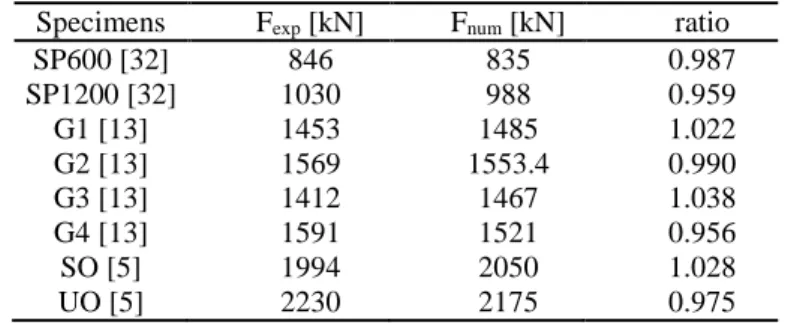
The magnitude of the global imperfection is scaled to hw/200 and the local imperfection is scaled to the web subpanels depth with hw,i/200. The results showed that there are no large differences (smaller than 2-3%) between the ultimate loads using different imperfection shapes, or different signs. The application of both imperfection shapes (local and global), however, is necessary to approximate the ultimate resistance with adequate accuracy. Therefore, in the case of stiffened web girders the parametric studies are based on the combination of the global and local imperfection shapes. Numerical models of eight test specimens are re-built and the validation is made by the comparison of the results obtained in the test and the numerical calculations; the results are summarized in table 1. The ultimate shape and the failure modes observed in the tests and in the numerical simulations are also compared, which showed good agreement. The largest difference on the unsafe side between the measured and computed resistances is 3.8% (specimen G3), however, the average of the differences is obtained to 0.994 on the safe side.
Table 1: Model validation based on the load carrying capacities.
Specimens Fexp [kN] Fnum [kN] ratio
SP600 [32] 846 835 0.987
SP1200 [32] 1030 988 0.959
G1 [13] 1453 1485 1.022
G2 [13] 1569 1553.4 0.990
G3 [13] 1412 1467 1.038
G4 [13] 1591 1521 0.956
SO [5] 1994 2050 1.028
UO [5] 2230 2175 0.975
5 INVESTIGATED PARAMETER RANGES
In the numerical analysis the following parameter domain is analyzed, which has a significant importance from the point of view of the validity interval of the studied M-V interaction model. For the numerical parametric study 40 typical unstiffened and 121 typical longitudinally stiffened cross-section geometries are selected with the parameter ranges as follows:
hw 300 – 3000 mm,
tw 3 – 16 mm,
bf 200 – 550 mm,
tf 10 – 50 mm,
hw/tw 50 – 200,
bf/tf 7.5 – 22.5,
α 1.5 – 2.0,
Af/Aw 0.22 – 6.11,
γ 23 – 8000 (closed section stiffeners),
γ 11 – 2300 (flat open section stiffeners),
where α is the aspect ratio of the web panels. Beside the geometries of the web and the flange plates, the number and the geometry of the stiffeners are also varied in the analysis. Closed section and open section stiffeners are also investigated, since they have significantly different structural behavior coming from the different torsional stiffness. A total of six different stiffener types are selected to the analysis: two closed section stiffeners and four open section (flat) stiffeners, which are varied in the research program. The number of the stiffeners are also varied between 2 and 3, because the Eurocode based resistance model is different for girders having 1-2 and 3 or more longitudinal stiffeners. Both categories are analyzed and evaluated separately.
All the cross-section geometries belong to cross-section class 3 or 4 according to the EN 1993- 1-5, and all the girder geometries fulfill the sensitivity requirement of shear buckling defined by equation 14.
=48.82 (14)
Figure 9 presents the investigated girder geometries evaluated based on the bending resistance models. The horizontal axis represents the flange over web cross-sectional area ratio (Af/Aw) while the vertical axis represents the ratios of the different bending moment resistances.
The result of the simulations showed that the Af/Aw, Mf/Mpl and Mf/Mel ratios have significant importance in the M-V interaction behavior, therefore the analyzed parameter range is also given using these ratios. It can be observed that the Mf/Mpl ratio represented by blue line is a continuous function in the case of unstiffened webs which monotonically tends to 1.0, if Af/Aw
72
w w
t h
increases. The other two ratios Mf/Mel,eff and Mel,eff/Mpl, however, cannot be given as continuous functions but the same increasing tendency can be observed. In the case of stiffened webs none of the ratios has continuous characteristics. It is clear that greater Af/Aw ratio indicates decreasing tendency in the resistance reduction for the M-V behavior. In the current research program there is a special focus on the applicability of the current design methods, to check its safe solutions especially in the parameter domain marked by red in figure 9. In addition, it can be seen that the investigated Af/Aw ratio is greater for stiffened girders, since thinner webs can be applied when stiffeners are placed on the web.
a) longitudinally unstiffened web b) longitudinally stiffened web Figure 9: Investigated parameter domain.
6 INVESTIGATION OF THE M-V INTERACTION BEHAVIOR 6.1 Research strategy
In the analysis all the studied girder geometries are investigated with seven intermediate points of the interaction representing different M/V ratios. The total number of the executed numerical simulations is more than 1350. During the study both the ultimate resistances and ultimate shapes are investigated. The FEM based capacities are compared and statistically evaluated by the design interaction equations of the EN 1993-1-5 and by the other proposed interaction curves (equation 12). The statistical evaluation is based on the distance between the numerically computed resistances and its central projection to the proposed interaction curve.
In the case of longitudinally stiffened web girders the investigation is performed using the reduced (Isl/3) or the full (Isl) moment of inertia of the longitudinal stiffeners. It has to be highlighted that the cross-section location where the evaluation is made has an important role in the process. Several researchers have already investigated the effect of the interaction check location because the moment gradient has a positive effect on the M-V interaction behavior.
The standard prescribes a distance of hw/2 measured from the transverse stiffener based on the proposal of Basler [3], however, it does not mention the case of longitudinally stiffened web girders. Johansson et al. [12] and Sinur and Beg [6] proposed the location for the interaction check hw,i,max/2 to ensure safe side solution. In the current study the proposal of the standard (hw/2) is adopted in order to be on the safe side by the validation of the M-V interaction curve, since it can be applied by the designers using the rules of the EN1993-1-5 and the application of the location hw,i,max/2 would give more safe side solutions.
Figure 10: Interaction check location according to the EN1993-1-5 [2].
6.2 Longitudinally unstiffened web I-girders
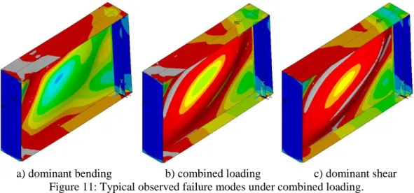
Figure 11 presents three typical failure modes and the relevant von-Mises stress distributions under different combined M-V loading situations (dominant bending; dominant shear; and their combination). The zones colored by grey represents yielding.
a) dominant bending b) combined loading c) dominant shear Figure 11: Typical observed failure modes under combined loading.
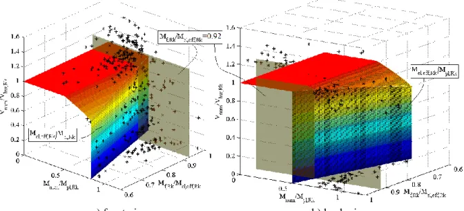
Figure 12 presents the calculation results for all the investigated unstiffened web cross- sections compared to the M-V interaction equation of the EN 1993-1-5. All the results are evaluated in the function of the Mf,R/Mel/eff,R ratio, which represents the dominancy of the flanges in the bending resistance, and therefore it has clear impact on the M-V interaction behavior.
The value of the bending resistance is represented in the paper by Mel/eff,R, which refers to the effective or elastic bending resistance depending on the relevant cross-section class. The horizontal axis represents the FEM based bending moment resistances divided by the plastic bending moment resistance (Mnum/Mpl,R), the other horizontal axis shows the Mf,R/Mel,eff,R ratio, while on the vertical axis the FEM based shear buckling resistance divided by the shear buckling resistance of the web alone (Vnum/Vbw,R) is described.
The vertical surface demonstrates the cut-off line of the design interaction model at Mel/eff,R/Mpl,R ratio for each girder, which should be also verified beside the M-V interaction check. It can be observed in the front and back views of the 3D diagram that girders having smaller Mf,R/Mel/eff,R ratio than 0.92 – demonstrated by the transparent gray vertical surface – the standard does not provide safe side solutions. It can be also observed that the smaller is the Mf,R/Mel/eff,R ratio the larger is the difference between the standard M-V interaction surface and
the numerical simulations. It means that for larger Mf,R/Mel/eff,R ratio than 0,92 all the calculation results are on the safe side. This parameter range is especially used in case of bridges. If the Mf,R/Mel/eff,R ratio is smaller than 0,92, there are points inside of the M-V interaction surface.
This parameter range is usually typical for building structures having relatively small flanges.
It should be highlighted, however, that there are no unsafe results even in this parameter range with smaller Vnum/Vbw,R ratio than 0,5, and for smaller bending moments than the flange moment resistance (Mf,R). Based on the results of the numerical simulations it can be also observed, that the difference in the shear buckling resistance and the shear resistance of the web panel alone (Vbw,R) is the highest in the parameter range of the safe side solutions (Mf,R/Mel,eff,R >0.92). It indicates that in this parameter range the standard M-V interaction equation can lead to conservative design, especially for bridges having relative large flanges. In this parameter range the original formulation of the EN1993-1-5 would be also applicable, or the consideration of the flanges in the shear buckling resistance could reduce the difference in the real and standardized resistances.
a) front view b) back view
Figure 12: Numerical results compared to the M-V interaction model of EN1993-1-5.
Table 2: Statistical evaluation of the results.
EN1993-1-5 Basler AASHTO DASt Shahabian
& Roberts
Sinur
& Beg Lee et al.
Average 1.070 1.080 1.106 1.363 1.125 1.090 1.100
SD 0.089 0.077 0.077 0.203 0.088 0.070 0.072
CoV 0.084 0.072 0.070 0.149 0.078 0.064 0.066
Min 0.850 0.956 0.959 1.033 0.968 1.000 0.974
Max 1.441 1.441 1.441 1.441 1.445 1.441 1.441
The statistical evaluation of the numerical results compared to the existing M-V interaction equations are shown in table 2. The average difference of the results from the M-V interaction equation of EN1993-1-5 is obtained to 7% on the safe side with a standard deviation of 0.089, and with the coefficient of variation of 0.084, the minimum difference is obtained to 15% on the unsafe side which is judged to be unacceptable for design resistance models used in the practice. The results show that the most favorable M-V interaction formula, which gives the best fit in case of longitudinally unstiffened girders to the numerical results is provided by Sinur and Beg [6]; the average difference is obtained to 9% on the safe side with a coefficient of variation equal to 0.064.
6.3 Longitudinally stiffened web I-girders
The observed typical failure modes with two and three longitudinal stiffeners under combined loading are presented in figure 13. Under dominant bending moment there are geometries with relative large stiffeners where the failure mode is the local buckling of the upper web panel closest to the flange in compression (figure 13a); in the case of weaker stiffeners global buckling occurred with accompanying stiffener buckling. The local shear sub- panel buckling and the global shear buckling are also separated by changing the stiffness of the stiffener and the slenderness ratio of the local sub-panel. The aim is to investigate geometries where the failure model is the global buckling of the whole web (figure 13b) and the local buckling of the sub-panels (figure 13c), representing the two typical situations which are covered by the Eurocode based shear buckling resistance model.
a) bending buckling b) local shear buckling c) global shear buckling Figure 13: Typical observed failure modes under combined loading.
Figure 14 shows the overall results regarding the longitudinally stiffened web girders with the similar way as presented by figure 12. The same observations can be seen as in the case of unstiffened web girder that girders having smaller Mf,R/Mel/eff,R ratio than 0.88 – demonstrated by the transparent gray vertical surface – the EN1993-1-5 does not provide safe side solutions.
It indicates that the revision of the standard’s proposal is necessary.
The statistical evaluation of the numerical results compared to the M-V interaction equation of EN1993-1-5 without the consideration of the flange shear resistance are also shown in table 3. In the table N represents the number of stiffeners. The average differences of the results are obtained to 45.6%, 40.5% and 22.5% on the safe side, respectively, with the minimum values smaller than 1.0 referring to the M-V interaction equation which shows the request for a slight modification on the current interaction equation.
a) front view b) back view
Figure 14: Numerical results compared to the M-V interaction model of EN1993-1-5 (Isl/3).
Table 3: Statistical evaluation of the EN1993-1-5 proposal (Isl/3).
Trapezoidal stiffeners N=2
Open flat stiffeners N=2
Open flat stiffeners N=3
Average 1.456 1.405 1.225
SD 0.357 0.337 0.158
CoV 0.245 0.240
0.957
0.129 0.957 1.531
Min 0.981
Max 2.176 2.996
7 DESIGN MODEL DEVELOPMENT
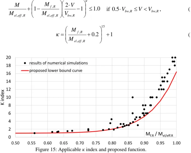
Investigations are performed to develop a refined M-V interaction equation to ensure a more economic design approach providing safe side solutions. The numerical parametric study showed that a slight increase in the M-V interaction diagram can be possible by changing the index κ from 1.0 (proposal of Sinur and Beg [6], equation 13) to an increased value. This optional change would be in harmony with the latest research results of Crisan and Dubina [28], who also proposed to change the value of κ to 1.5 for girders having cross-section classes 1 and 2. To investigate the appropriate value of κ in equation 13 an extended study is performed and the applicable index is determined for all the investigated cross sections.
The numerical results show that the applicable index strongly depends on the Mf,R/Mel/eff,R
ratio of the analyzed cross-section, therefore the index is evaluated in the function of it. The determined values of the κ index are presented by black points in figure 15 and the lower bound curve proposed for design purposes is presented by red continuous line. The currently proposed improved design M-V interaction equations are given in equations 15-16.
0 . 1 2 1
1
, ,
, , ,
,
R bw R eff el
R f R
eff
el V
V M
M M
M
if 0.5Vbw,R V Vbw,R, (15)
1 2 . 0
15
, ,
,
R eff el
R f
M
M (16)
Figure 15: Applicable κ index and proposed function.
0 2 4 6 8 10 12 14 16 18 20
0.50 0.55 0.60 0.65 0.70 0.75 0.80 0.85 0.90 0.95 1.00
K index
Mf.R/ Mel/eff.R results of numerical simulations
proposed lower bound curve
Figure 16 presents the 3D plot of the numerical simulation results for longitudinally unstiffened web girders compared to the currently proposed M-V interaction equation. It can be seen, that all the simulation results are on the safe side.
a) front view b) back view
Figure 16: Comparison of the numerical results with equations 15-16 for unstiffened girders.
Figure 17 shows the 3D plot of all the numerical results with the new interaction equation and considering the full stiffeners’ inertia in the shear buckling coefficient. It can be seen that all the points are above the modified interaction equation which fits quite good to the actual structural behavior for larger bending moments than the flange moment resistance alone (M>Mf,R).
a) front view b) back view
Figure 17: Comparison of the numerical result with equations 15-16 for stiffened girders with full Isl.
The statistical evaluation of the numerical results compared to the proposed M-V interaction equation are given in table 4. The average difference of the unstiffened web girders’ results from the interaction equation is obtained to 7% on the safe side with a standard deviation of 0.075. The coefficient of variation is obtained to 0.069. In the case of longitudinally stiffened web girders the statistical evaluation is also provided. In the statistics the provided values
consider the full stiffeners’ inertia (Isl). The concerning coefficient of variations are obtained to 0.198, 0.187 and 0.080 with minimum differences equal to 2.1%, 0.8% and 0.9% on the safe side.
Table 4: Statistical evaluation of the proposed M-V interaction equation considering full Isl.
unstiffened Trapezoidal stiffeners N=2
Open flat stiffeners N=2
Open flat stiffeners N=3
Average 1.073 1.329 1.298 1.148
SD 0.075 0.263 0.243 0.092
CoV 0.069 0.198 0.187
1.008
0.080
Min 0.988 1.021 1.009
Max 1.457 1.994 2.388 1.409
8 CONCLUSION
Based on the executed research program on the M-V interaction behavior of longitudinally unstiffened and stiffened I-girders with slender web the following conclusions are drawn:
- The Mf,R/Mel/eff,R ratio has significant impact on the M-V interaction behavior, therefore all the results are evaluated in function of this ratio.
- The M-V interaction equation of the EN 1993-1-5 does not provide safe side solutions for girders having smaller Mf,R/Mel,eff,R ratio than 0.88 in the case of longitudinally stiffened and 0.92 in the case of longitudinally unstiffened webs. For larger Mf,R/Mel/eff,R
ratios the standard M-V interaction equation gives safe side solution in the M-V interaction domain.
- The most favorable M-V interaction formula from the previously developed interaction equations, which gives the best fit to the numerical results is provided by Sinur and Beg [6].
- It is proved that the M-V interaction equation of the EN 1993-1-5 can also lead to significantly conservative resistances, especially for bridges having heavy flanges as observed by Hendy and Presta [4].
- It is also observed that the proposal of Sinur and Beg [6] and the observation of Hendy and Presta [4] are corresponding to different ranges of the M-V interaction diagram, therefore they can complement each other.
- An improved M-V interaction diagram is developed by changing the index κ from 1.0 to an increased value in the function of the Mf,R/Mel/eff,R ratio, which ensures better fit to the numerical simulations.
- The application of the full stiffeners’ inertia in the shear buckling coefficient could be applicable for stiffened girders, and the currently proposed M-V interaction equation would remain on the safe side.
ACKNOWLEDGEMENT
The presented research program was partly supported by the first author’s ÚNKP-17-3-IV.
New National Excellence Program of the Ministry of Human Capacities and by the second author’s ÚNKP-17-4-III New National Excellence Program of the Ministry of Human Capacities; the financial supports are gratefully acknowledged.
REFERENCES
[1] EN 1993-1-1:2005, Eurocode 3: Design of steel structures, Part 1-1: General rules and rules for buildings.
[2] EN 1993-1-5:2005, Eurocode 3: Design of steel structures, Part 1-5: Plated structural elements.
[3] Basler K., “Strength of plate girders under combined bending and shear”, Journal of the Structural Division ASCE, 87(7), 181-197, 1961.
[4] Hendy C.R., Presta F., “Transverse web stiffeners and shear moment interaction for steel plate girder bridges”, The Structural Engineer, November, 2008.
[5] Sinur F., Beg D., “Moment-shear interaction of stiffened plate girders – Tests and numerical model verification”, Journal of Constructional Steel Research, 85, 116-129, 2013.
[6] Sinur F., Beg D., “Moment-shear interaction of stiffened plate girders – Numerical study and reliability analysis”, Journal of Constructional Steel Research, 88, 231-243, 2013.
[7] Kövesdi B., Alcaine J., Dunai L., Mirambell E., Braun B., Kuhlmann U., “Interaction behavior of steel I-girders under bending, shear and transverse force, Part I: Longitudinally unstiffened girders”, Journal of Constructional Steel Research, 103, 327-343, 2014.
[8] Kövesdi B., Alcaine J., Dunai L., Mirambell E., Braun B., Kuhlmann U., “Interaction behavior of steel I-girders under bending, shear and transverse force, Part II: Longitudinally stiffened girders”, Journal of Constructional Steel Research, 103, 344-353, 2014.
[9] Braun B., “Stability of steel plates under combined loading”, PhD thesis No. 2010-3 Institute for Structural Design, Universität Stuttgart, 2010.
[10] Höglund T., “Shear buckling resistance of steel and aluminium plate girders”, Thin-Walled Structures, 29, 13-30, 1997.
[11] Crate H., Lo H., “Effect of longitudinal stiffeners on the buckling load of long flat plates under shear”, NACA Technical Note, No. 1589, 1948.
[12] Johansson B., Maquoi R., Sedlacek G., Müller C., Beg D., “Commentary and worked examples to DIN-EN-1993-1-5 Plated Structural Elements”, 2007.
[13] Pavlovčič L., Detzel A., Kuhlmann U., Beg D., “Shear resistance of longitudinally stiffened panels – Part 1: Tests and numerical analysis of imperfections”, Journal of Constructional Steel Research, 63, 337-350, 2007.
[14] Pavlovčič L., Beg D., Kuhlmann U., “Shear resistance of longitudinally stiffened panels – Part 2:
Numerical parametric study”, Journal of Constructional Steel Research, 63, 351-364, 2007.
[15] Way S., “Stability of rectangular plates under shear and bending forces”, Journal of Applied Mechanics, 3(4), A,131, 1936.
[16] Gerard G., Becker H., “Handbook of Structural Stability, Six Parts”, NACA Technical Notes, Nos.
3781-3786, 1957/1958.
[17] Rockey K.C., “An ultimate load method for the design of plate girders”, Proc.
Colloquium on Design of Plate and Box Girders for Ultimate Strength IABSE, 253-268, 1971.
[18] Alinia M.M., Moosavi S.H., “Stability of longitudinally stiffened web plates under interactive shear and bending force”, Thin-Walled Structures, 47, 53-60, 2009.
[19] Höglund T., “K18, Design of steel structures”, Chapter K18 and K19 from the building handbook (in Swedish), SBI, KTH Royal Institute of Technology, Stockholm, 1994.
[20] EN 1999-1-1:2007, Eurocode 9: Design of aluminium structures, Part 1-1: General structural rules.
[21] STN 73 1401 Navrhovanie oceľových konštrukcií (Design of steel structures), SÚTN Bratislava, March, 2008.
[22] ČSN 73 1401 Navrhování ocelových konstrukcí (Design of steel structures), ČSNI Praha, March, 2008.
[23] Shahabian F., Roberts T.M., “Behavior of plate girders subjected to combined bending and shear loading”, Scientia Iranica, 15(1), 16-20, 2008.
[24] Fujii T., Fukomoto Y., Nishino F., Okamura T., “Research works on ultimate strength of plate girders and Japanese provisions on plate girder design”, Proc. Colloquium on Design of Plate and Box Girders for Ultimate Strength IABSE, 21-48, 1971.
[25] Herzog M., “Ultimate static strength of plate girders from tests”, Journal of the Structural Division ASCE, 100(5), 849-864, 1974.
[26] Lee S., Lee D., Yoo C., “Flexure and shear interaction in steel I-girders”, Journal of Structural Engineering, 139(11), 1882-1894, 2013.
[27] AASHTO. LRFD bridge design specifications, Washington, DC: American Association of State Highway and Transportation Officials, 2004.
[28] Crisan A., Dubina D., “Bending-shear interaction in RBS short coupling beams”, Proc. European Conference on Steel and Composite Structures EUROSTEEL 2014, Napoli, Italy, 2014.
[29] DASt Richtlinien 015, Träger mit schlanken Stege, Stahlbau-Verlag, Köln, 1990.
[30] Jáger B., Kövesdi B., Dunai L., “I-girders with unstiffened slender webs subjected by bending and shear interaction”, Journal of Constructional Steel Research, 131, 176-188, 2017.
[31] ANSYS® v15.0, Canonsburg, Pennsylvania, USA.
[32] COMBRI: “Competitive Steel and Composite Bridges by Improved Steel Plated Structures”, Final Report, RFCS Research Project RFS-CR-03018, 2007.


![Figure 6: Test girders of COMBRI project [32] used for validation – unstiffened web](https://thumb-eu.123doks.com/thumbv2/9dokorg/1401220.117409/9.892.153.737.897.1083/figure-test-girders-combri-project-used-validation-unstiffened.webp)
![Figure 8: Test girders of Sinur and Beg [5] used for validation – open stiffeners.](https://thumb-eu.123doks.com/thumbv2/9dokorg/1401220.117409/10.892.130.774.358.773/figure-test-girders-sinur-beg-used-validation-stiffeners.webp)