III. Manifestations of Nuclear Magnetic Shielding in NMR Spectra of Solids
A. General Remarks
We have already stated that measuirng the NMR parameters σι, Dik, V1', etc., is one of the principal goals of experimental NMR. There are three main factors governing the experimenter's access to these parameters:
(1) the relative size of the internal Hamiltonians,
(2) the averaging processes operative—intentionally or unintentionally—
in both ordinary r and spin spaces,
(3) the manner in which the internal Hamiltonians manifest themselves in NMR spectra, particularly in NMR spectra of solids.
In many cases Jtf D greatly exceeds other internal Hamiltonians, in particular J»fcs. It then renders σ inaccessible to measurement. In isotropic liquids, fast random molecular motions average out 3tfO, but likewise they average out all anisotropic constituents of 3tfcs. Only the isotropic constituent of σ becomes measurable. The major achievement of selective averaging by multiple-pulse sequences is that it provided a technique by which it is possible to suppress JfD in solids by an averaging process in spin space that leaves alive all con- stituents of Jfcs. By this technique the full σ tensors become accessible to measurement.
In this chapter we discuss the types of spectra encountered when 3tfcs either is the dominant part of the total spin Hamiltonian or when it is made the dominant part by selectively suppressing the homo- and heteronuclear dipolar spin-spin coupling terms.
Let us consider a perfect single crystal and let us recall two definitions:
Two nuclei are called crystallographically equivalent if they are related by any one of the symmetry elements of the space group of the crystal.
17
18 III. SHIELDING IN NMR SPECTRA OF SOLIDS
Two nuclei are called magnetically equivalent if they are related by one of the translation and/or inversion elements of the space group.8 These latter symmetry elements constitute an invariant subgroup of the space group.
Using these definitions, we may state:
(1) The tensorial parameters σ and V are identical for magnetically equivalent nuclei, i.e., σι = σΛ, V* = Vfc for magnetically equivalent nuclei / and k.
(2) σ and V of crystallographically equivalent nuclei / and k are related by the rotation-reflection parts of the symmetry operations by which the nuclei / and k are related. The invariance of σ and V against inversions is a consequence of the symmetry of these tensors (σαβ = σβα; Vaß = Vßa9 or alternatively, ρξ±? = 0). Effects of hypothetical nonvanishing constituents of σ are discussed below.
(3) The NMR spectra of idealized samples, in which only single-particle Hamiltonians such as Jfcs and ^fQ are operative, are independent super- positions of the spectra from magnetically nonequivalent nuclei.
Each partial spectrum consists of Nt sharp lines, where Nt depends on the spin quantum number / and the ratio hco0i/e2qiQi. For hco0l/e2qiQl > 1, Nt = 21.
For / = ·£, Nt is just 1. Line splitting, and eventually line broadening, is caused by the many-particle interactions J^D and J^}. We disregard them in this chapter.
If there are Nm magnetically nonequivalent sites for a given isotope in a single crystal, its (idealized) NMR spectrum consists of 7VzxNm sharp lines.
In special orientations of the crystal with respect to Bst some of the lines will coalesce. In any case the number of lines is limited, although often it is not very small.
Let us consider a crystal with Nc crystallographically equivalent but magnetically nonequivalent sites for an isotope with, say, spin I =\. These sites contribute Nc lines to the spectrum. Of course, we would like to know which of these lines arises from which site. Now it is very important to realize that it is impossible in principle to decide—on the basis of complete structural and NMR information—which of these lines must be assigned to which site.
In other words, there is no symmetry argument on which an assignment could be based. With the procedures to be described in the following section we
8 Note that neither crystallographically nor magnetically equivalent nuclei are automatically equivalent nuclei according to the definition used in high-resolution NMR in fluids, where equivalence is defined with respect to molecular symmetry, and scalar couplings Jifc are taken into account.9
9 A. Abragam, "The Principles of Nuclear Magnetism," Chapter XI, p. 480. Oxford Univ.
Press (Clarendon), London and New York, 1961.
B. SINGLE CRYSTALS AVAILABLE 19 can, in principle, determine a σ tensor for each of the Nc lines. These tensors transform among themselves under the symmetry operations by which the crystallographically equivalent sites are related.
Crystallographically nonequivalent sites can, in general, be distinguished:
The corresponding σ tensors cannot be brought into exact coincidence by any one of the symmetry operations of the space group. There is, however, still the question of which set of lines (or σ tensors) belongs to which set of crystallographically equivalent sites. Again there is no symmetry argument that allows an assignment of the different sets of related lines to the cor- responding sets of crystallographically equivalent sites if these sites are general sites. Special sites, however, can be distinguished from general sites.
Sites on «-fold axes, as well as on screw axes, mirror and glide planes, and inversion centers are called special sites.
The lines from two sites related by, e.g., a mirror plane coincide when Bst
falls into that mirror plane. This line then has double intensity in comparison to a line from a site on the mirror plane. More important, however, the former line splits when Bst moves out of the mirror plane, whereas the latter does not.
For magnetic resonance experiments planes perpendicular to «-fold axes (screw axes) are equivalent to mirror planes. Lines from sites on inversion centers can be distinguished from other lines again by their smaller intensity.
In summary, symmetry arguments are very valuable for handling the assignment problem, but often they do not lead to its complete solution.
Assignments must then be based on additional information, for instance, NMR data from related compounds, or on theoretical grounds. Such assign- ments are usually highly reliable but inevitably they incorporate some kind of assumption.
B. Single Crystals Available
We start with a case in which all sites are magnetically equivalent for the isotope in which we are interested. For simplicity we suppose / = \. There is only one line in the spectrum. We ask ourselves how we can determine the desired shielding parameters from the spectral position of this line. Obviously we must render the line position dependent on an external parameter. The orientation of the crystal with respect to the external magnetic field plays the role of this external parameter.
In the approximation—usually an excellent one—in which we restrict ourselves to secular terms of the internal Hamiltonian [terms with m = 0 in Eq. (2-16)] the position of the one line in the spectrum is governed by
■#CS, secular = )>n'θ * 0 {*' + V I * 2 θ ' ' } = Ö>0/0 {** + V * ^ o )
20 III. SHIELDING IN NMR SPECTRA OF SOLIDS
[cf. Eq. (2-27)]. To save indices we set Βξ%* = σ2γη. The upper Zeeman level (mj = -i) is shifted by an amount -^ω0{σί+^σ20), and the lower {rm = +■£) by the same amount in the opposite direction. Hence the position col of the line relative to the position cob of the line of the bare nucleus (ab = 0) is given in units of 2π Hz by
col-cob = -ω0{σ'' + νΐσί>ο} = - ω0< 4 · (3-1) The position of the line of the bare nucleus is not known. Therefore, in
practice, we do not reference ω1 against cob, but against a/ef, which is the line position of a reference sample for which σ20 vanishes for one reason or another (e.g., motional averaging or cubic crystal symmetry).
ωί _ ω^ = _ω ο{σί _σΓβί + ^σ,2 ο} ( 3 - 2 )
is all that we can measure in an NMR experiment. The scalar shielding parameter that we can measure—in principle, not only in practice—is not
^ b u t a ' - a " * .
In Eq. (2-30) we have expressed σ20 in terms of δ\ r( and ß\ f. Recall that ßi and / are the Euler angles by which the laboratory system of coordinates (henceforth denoted by LABS) can be brought into coincidence with the PAS of σ\ Although βι and yl are parameters on which ωι — coref directly depends, they are not the parameters in which we are ultimately interested.
The parameters in which we are ultimately interested are σ1 — <5ref, δ\ η\ and the Euler angles a/, /?/, y{ ( = Ω/), which relate some arbitrarily chosen, crystal fixed orthogonal axes system (CRS) with the shielding principal axes system.
What is needed, therefore, is an expression for σ20 in terms of δ\ η\ Ω/, and the Euler angles a", ß", y" (=Ω"), which relate the laboratory and the crystal fixed frames. Such an expression is obtained easily by applying Eq.
(2-20) twice:
^o(LABS) = g ^ O ^ V U C R S ) = Σ ^ ο ( Ω " ) Σ ^ ν ( Ω / ) Ρ Ϊ "
= Σ »i'o (Ω") # \Ά ®L· (an + W \9L· (Q/)+^
2-
2« («/)]]·
m' (3-3)
Recall that the @^,0 actually do not depend on a". In fact, ωι must not depend on a" since the line position must be invariant under rotations of the crystal about the external magnetic field.
Often it is very useful to express the relation between the LABS and the CRS not by the Euler angles a", ß", y"—which are always hard to visualize, and one of which does not enter the result in any case—but by the polar angles θ, φ9 which specify the direction of the external magnetic field in the
B. SINGLE CRYSTALS AVAILABLE 21 crystal fixed frame, ß", y" and $ ,φ are related by
β" = S, (3-4a) / ' = π - φ (3-4b) (see, e.g., Fig. 1.1 of Edmonds1).
Using Eqs. (2-24b), (3-4a), and (3-4b), and well-known symmetry relations among the spherical harmonics, we get
®2m.0(ß") = (-i)m'W5)ll2Y2Aß",y")
= (-ΐΠ4π/5)1/2Υ2ηι,φ,π-φ)
= (4π/5)1/272,_„,(θ,φ). (3-5)
Inserting Eqs. (3-5) and (3-3) into Eq. (3-2) gives the line position in terms of the desired parameters:
ω< - ω'« = - ω0\ σ ' - σ"{ + (8π/15)1/2<5' £ YW( S ,Ψ )
χ [ßl2)
U2®l
mm + W (®L· OV)+Sl
2Μ-(Ω/))]
(3-6)
# and φ are external parameters. Six different, nondegenerate choices of 9, φ lead to six different line positions from which we may calculate, in principle, the desired parameters. This is, however, not the typical procedure.
Usually one rotates the crystal about an axis perpendicular to the external field and records what is called a rotation pattern. Stated differently, one records ω' — o>ref when the external field moves in a plane of the crystal.
Three rotation patterns with three different choices of the rotation axes are usually needed. The rotation patterns are always of the form
-Wm-co^/cDo = a + A1 cos2(0-Oil a x), (3-7) where Φ is the rotation angle (counted from an arbitrary zero); C\ A\ and
<I>max are constants that are (complicated) functions of a/, /?/, y/f σ1 — aref, <5\ η\
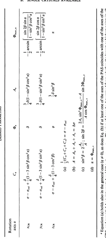
and of the choice of the rotation axis. These functions become reasonably simple only if ηι = 0 (axially symmetric shielding tensor) and if we choose the axes xCR, >>CR, zCR of the CRS as rotation axes. Figure 3-1 and Table 3-1 show how we get the desired internal parameters directly from the rotation patterns in such a simple case.
In the general case (η Φ 0) one usually determines these parameters by a least-squares computer fit analysis of the data of the rotation patterns.
Equation (3-6) is a good starting point for the required program.
22 HI. SHIELDING IN NMR SPECTRA OF SOLIDS
\ ΧΥ-ρ^ηε
jl*E»L j 9m
(b)
FIG. 3-1. (a) Example of rotation patterns when σ is axially symmetric; δ > 0, a = 30°, β = 60° have been chosen. The lowest points in each pattern are the same. For S < 0 the highest points would be the same. Note what is plotted on the ordinate axis! ω is the resonance position of the line for B0 = const; ω0 =γηΒ0.
(b) Stereographic projection of (1) the crystal fixed frame ^C R, ^CR , ZCR\ (2) the unique shielding axis (Z) and the XY plane of the shielding principal axes system; (3) the paths of Bst when the crystal is rotated about the zCR, J>CR, and JCCR axes; the rotation axis is always perpendicular to Bs t; (4) 0>maXfJC, <Dmax,y, <J>max,z; Omin,*, Φη,ΐη.,, Φπϋη,*.
When taking rotation patterns it is always wise to draw a figure like (b).
TABLE 3-1 CONSTANTS A, C, AND ΦΠ13Χ IN EQ. (3-7) WHEN σ is AXIALLY SYMMETRIC, AND RELATIONS FOR OBTAINING FROM THEM THE DESIRED PARAMETERS0 Rotation axis a Φ* Aa Φ. •*CR .VCR ■ZCR
σ — aref + - (1 — 3 sin2 /? cos2 a) 4 σ — σΓ6ί + - (1 — 3 sin2 /? sin2 a) 4 σ — σΓβΓ + -(1 - 3 cos2 /?) 4 (a) -(Cx+ Cy+ Cz) = σ - σΓβΓ (b) Λ = Ax + Λ, + Az = Δσ
-<5(l-sin2 /?cos2 a) 4 -<5(l-sin2 £sin2 a) 4 -<5sin2 A (c) sin2 £ = 2—; sin2£ = (d) a = Omax,z
2/4z sin2 Φ„ A cos Φπ, 8ΐη2Φπ13Χ,),
— arcsm 2 - - arcsin 2
sin 2/? sin a 1 — sin2 /? cos2 a J sin 2/? cos o 1 — sin2 /? sin »sal
2!
g
CO 52 r co > P > Cda Equation (a) holds also in the general case (η φ 0), as does Eq. (b) if at least one of the axes of the PAS coincides with one of the axes of the CRS, and provided Δσ is interpreted as i<5(3 + ή) = σζζ — ^χχ · The sign of δ can be determined from whether the lowest or highest points in all patterns are the same or nearly the same for 1 > η φ 0. For δ < 0 "max" must be replaced by "min."
24 III. SHIELDING IN NMR SPECTRA OF SOLIDS C. Only Powders Available10
1. POWDER PATTERN LINESHAPES
A powder consists of a multitude of randomly oriented single crystals.
Consider a group of crystallographically equivalent nuclei and suppose that their shielding tensors are axially symmetric. If we plot the orientations of the unique axes of all these tensors in the powder sample on a sphere we get a distribution that is constant over the sphere. Alternatively, we may plot on a sphere the direction of Bst (specified by 9, φ) as seen in the PAS of each nucleus.
This alternative makes it easy to drop the restricting assumption of axially symmetric shielding tensors.
The distribution we get is again constant over the sphere. Each point on the sphere corresponds to a definite orientation of Bst with respect to a shielding principal axes system and hence to a definite NMR spectral line position. It is obtained from Eq. (3-6) by setting Ω/ = (0,0,0), which means making the CRS and the PAS coincide. Since i^2«m,(0) = dm„m> we obtain
o/_a)r e f = -ω0{σΛ-σηΧ + (βη/15)1/2
x δ* l(3/2y<2Y20(3, φ) + W(Y2t2(θ, φ) + 72,_2 (θ, φ))]}
= - ω ο ί ^ - σ ^ + <5f[i(3 c o s2S - l) + W sin25 cos2<p]}.
(3-8) The orientational dependence of the line position is contained in
ω = ω0 δH(3 c o s2θ - 1 ) + \r\ sin2θ cos2φ], (3-9) where, for simplicity, we have dropped the indices / from the parameters η
and δ. Using Eq. (3-9) we now can draw curves ω = const on our sphere.
Two examples are given in Figs. 3-2 and 3-4.
The NMR spectrum of a powder sample is a superposition of the NMR lines from all the nuclei of all the grains of the sample. The intensity /(ω) of the spectrum, when integrated over an interval (ua--a>h is proportional to the number of nuclei whose NMR lines fall into that interval. This means it is proportional to the area between the curves ω = ωα and ω = cob on our sphere (it is clear that we need consider only one hemisphere, in fact, only one octant of the sphere):
10 The subject matter of this section is treated, e.g., by Bloembergen and Rowland.11'12 However, it is our experience that students often have a very hard time following their articles. Therefore, we discuss here the underlying ideas in a rather detailed manner and hope that this is warranted from a didactic point of view.
11 N. Bloembergen and T. J. Rowland, Acta Met. 1, 731 (1953).
12 N. Bloembergen and T. J. Rowland, Phys. Rev. 55,1679 (1955).
C. ONLY POWDERS AVAILABLE 25
3=0
3=7Γ
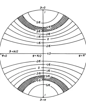
FIG. 3-2. Stereographic projection of curves ω = const (actually curves 3 = const) when σ is axially symmetric, η = 0. Units are ω0δ. Notice the large distance of the curves for S->0 and $->πβ.
J
*0)ωα b I(co) dco - * / / sin 5 d9 dq>. (3-10)between curves ω = ωα
and ω = cob
TV is a normalization factor which we are free to choose in such a way that Ji^ Ι(ω) άω = 1. JV = 2/π if eventually we integrate over one octant of the sphere.
First let us consider the special case η = 0.
Figure 3-2 shows the curves ω = ωη = const. Equal increments of ωη have been chosen, ω depends only on 5. The curves ω = const are actually curves 5 = const. We integrate Eq. (3-10) over φ (from φ = 0 to <p = π/2). In the remaining integral over $ we introduce
ω = ω0δ 3 c o s2S - l as a new integration variable. This gives
L
Ι(ω) d(°
=7 f ^ L ίΙ + (2ω/ω
dco 0δ)Υ'
2·
(3-11)26 III. SHIELDING IN NMR SPECTRA OF SOLIDS
Equation (3-11) holds for arbitrary integration limits ωα, ω&; hence we can equate the integrands and obtain
I(co) = — —γ π , -ω0δ/2 < ω ^ ω0δ.
^3ω0δυ+(2ω/ω0δ)γ/2
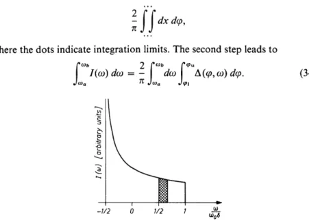
(3-12) Figure 3-3 shows Ι(ω), which is the idealized powder pattern when σ is axially symmetric. It diverges for ω -► — %ω0 δ. We hope that Figure 3-2 provides a
"look and see" understanding for this divergence. Note, in particular, the spacing of the curves ω = ωη! Figure 3-3 also makes clear how the desired internal parameters σ — aref and Δσ = § δ can be determined from a powder pattern. Naturally no information about the direction of the unique axis relative to a crystal fixed frame can be derived from powder patterns.13
To treat the general case, η Φ 0, let us first introduce x = — cos # and then co = %ω0δ[3χ2 —1+*7(1— x2) cos2(p] as new integration variables in the right-hand integral of Eq. (3-10). The first step leads to
Hi
dx d(p,where the dots indicate integration limits. The second step leads to
J
%a>b 2 ΓΙ(ω)άω = - dco Α(φωι> Γφχχ 9ω)αφ.(3-13)
FIG. 3-3. Powder pattern when σ is axially symmetric. The divisions on the axis corre- spond to the lines ω = const in Fig. 3-2. Similarly, the shaded areas in Figs. 3-2 and 3-3 correspond to each other.
13 By comparing 19F multiple-pulse powder patterns of C6F6 at different temperatures and exploiting the knowledge that C6F6 molecule rotates rapidly about their 6-fold axes in the solid state at higher temperatures Mehring et al.14, were able to determine the unique axis of the 19F shielding tensor. C6F6, however, is an exceptional case.
14 M. Mehring, R. G. Griffin, and J. S. Waugh, /. Chem. Phys. 55, 746 (1971).
C. ONLY POWDERS AVAILABLE 27
φι and cpu are the lower and upper integration limits of the (^-integral, respectively. We shall specify them shortly. Α(φ,ω) is the Jacobian d(cp, χ)/δ(φ, ω), which reduces to
-1/2
(3-14) We have introduced the abbreviation ω3 = ω0 δ and similarly we shall define ω2 = — \ω0δ(\—η) = ω0σ(γ2^ anda^ = — %ω0δ(\+η) = ω0σί^. By the same argument used in the paragraph following Eq. (3-11) we can now equate the integrands of the ω integrals in Eq. (3-13):
2 />« [2ω \ "1 / 2
Ι(ω) = (3->7COs2(p)"1/2 — + 1 -?ycos2^ άφ.
πω3 )φ ι \ω3 )
(3-15) Let us now turn to φι and cpu. We integrate only over one octant of the sphere; we choose the upper left one in Fig. 3-4. It is clear from Fig. 3-4 that we must distinguish two cases:
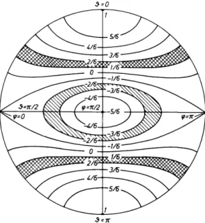
FIG. 3-4. Stereographic projection of curves ω = const when σ is nonaxially symmetric.
η — i has been chosen in this example. Units are ω0δ = ω3. For ω/ω3 < ω2/ω3 = — i(l — η) the curves cross the equator. The crossing meridian ψχ is determined by ω/ω3 =
- i [ l - ^ c o s 2 ^ , ] .
οω ω31 η cos 2φ) I h 1 — η cos 2φ ω3
28 III. SHIELDING IN NMR SPECTRA OF SOLIDS
(ι) ω2 ^ ω < ω3 -* φ, = 0, (pu = - , π
(ii) ωχ < co < ω2 -> (pt = - arccos
E('^]-i·
To proceed, we introduce the new integration variable z = cos2(p. We get
{C0) πω3η)ζι [(1-ζ2)(3^-ζ){(1/^)[(2ω/ω3)+11-ζ}]1/2 ' 1 (2ω \
zu = 1 (case i), zu = -1 h i (case ii), z, = — 1 (cases i, ii).
This integral is tabulated, e.g., in the "Table of Integrals, Sums, Series and Products" by Gradshteyn and Ryzhik.15 Note that the zeros zn of the poly- nomial under the root are known; note also that the sequence of the zn's (which is crucial) is different in cases i and ii.
Calculating the required parameters from zl9 zu9 and the zn's we finally get Ι(ω) = π [ ( ω3- ω2) ( ω - ω1) ] % ω ^ ω ^ ω ^ ω ΰ ) ' 2}
1 1(ω3-ω2)(ω-ωί)] J (3-16a) for ω2 < co < ω3, and
Ι(ω) = π 1[ ( ω3- ω ) ( ω2- ω1) ] 1,2FU ,-\
11(ω3-ω)(ω2-ωι)_\ 2J
= π-1 [( α > 3 - ω ) ( ω2- ω1) ] -1^ { 3 Γ 05ί η [ ^ -ω;)/(" -ω ι; 11 / 2} [ Ι((ο3-ο))(ω2-ω1)_\ J
(3-16b) for ωχ < ω < ω2.
.F(&, <ρ) is the (incomplete) elliptic integral of the first kind, and, AT(arcsinA:) = F(k,n/2)
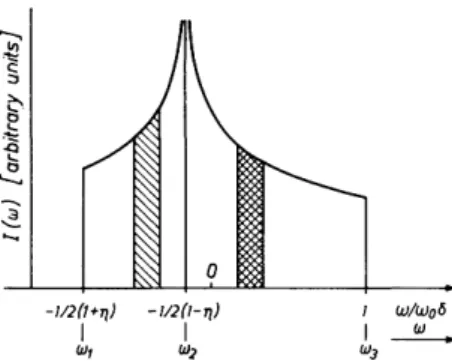
is the complete elliptic integral of the first kind. We have normalized I(co) such that the area under I{co) is unity. Figure 3-5 shows an example. The discontinuities ω3, ω2, ωί immediately yield σζ ζ, σΥΥ9 σχχ or, alternatively,
<5, η9 and σ.
Before leaving the subject of nuclear-shielding powder lineshapes a final
1 51 . S. Gradshteyn and I. M. Ryzhik, "Table of Integrals, Sums, Series and Products,"
4th ed., pp. 241-242. Academic Press, New York, 1966.
C. ONLY POWDERS AVAILABLE 29
FIG. 3-5. Powder patterns when σ is nonaxially symmetric (η = $). The divisions on the axis correspond to the lines ω = const in Fig. 3-4. Again, the differently shaded areas in Figs. 3-4 and 3-5 correspond to each other. Two abscissa axes are indicated for convenience.
remark should be made. We have already emphasized that by investigating powders one does not get information about principal shielding directions.
Hence single-crystal studies are always potentially superior to powder studies.
In practice, however, there may be exceptions to this rule. Remember that all crystallographically equivlaent nuclei contribute to one and the same powder pattern. Now, in molecular solids the nuclear shielding is often dominated so much by molecular properties that not only all crystallographically, but all chemically equivalent nuclei (nuclei related by molecular symmetry operations) contribute to one and the same pattern. This may result for highly symmetric molecules (C6F6, P4, C6H6, etc.) in powder patterns simple enough to be analyzed, whereas the corresponding single-crystal spectra may resist an analysis due to too large a number of often unresolved lines.
2. MOMENTS OF SHIELDING POWDER PATTERNS
The «th moment of a (normalized) lineshape function Ι(ω) or, in other terms, the mean value <ωη> of con is defined as
<ω">
-r
J-o 1{ώ)ωηάω. (3-17)This definition requires a specification of the point about which the moments are to be taken. We choose it such that <ω> = 0. This choice is consistent with Eq. (3-9). We call that point in the spectrum ω. ω and <ω2> of pure shielding powder patterns can be determined experimentally even when the experimental patterns are strongly affected by internal Hamiltonians other than J4?CS9 e.g., by JfD. The precise conditions under which this holds true are discussed by Van der Hart and Gutowsky.16
16 D. L. Van der Hart and H. S. Gutowsky, /. Chem. Phys. 49,261 (1968).
30 III. SHIELDING IN NMR SPECTRA OF SOLIDS
A third quantity that is accessible experimentally is ω1 / 2 defined by
Γ 1{ω)άω = \. (3-18)
•/ωι/2
ω1 / 2 divides the area under Ι(ω) in two equal halves. For symmetric patterns ω1 / 2 = ω.
By inserting the squares of both sides of Eq. (3-9) in both sides of Eq. (3-10) and extending the integration limits appropriately, we obtain in a straight- forward manner
<ω2> = (ω0δ)2^(3 + η2). (3-19) We were unsuccessful in finding an explicit formula for ω = ω1 / 2; therefore,
we give in Fig. 3-6 a graphic plot of /(η) = (ω0δ)_ 1 |(ω — ω1 / 2)| versus η.
To determine δ and η (σ is fixed by ω itself) from measured values of ω, ω1 / 2, and <ω2> a plot of
g{n) = < ω2> "1 / 2| ω - ω1 / 2| = Λη) [15/(3+ η2)^2
is helpful and is given in Fig. 3-6. g is a measurable quantity. Knowing g we can immediately get η from Fig. 3-6. Knowing η and <ω2> one can find δ from Eq. (3-19). The sign of δ is the same as the sign of ω — ω1 / 2.
This is a simple procedure to determine δ and η ( and σ). However, we are afraid that it will rarely produce accurate results, at least as far as η is con- cerned. Its drawback is that \ω — ω1 / 2| never exceeds - ^ of the total width of the spectrum. Therefore, nowadays most workers prefer to analyze their powder patterns by least-squares computer fit programs, as we do ourselves.
Nevertheless, the procedure described above may help sometimes to get quickly results, if only preliminary ones.
.12
I .70-
5 08'
.06- .04-
0- .2 .4 .6 .8 1 .2 .4 .6 .8 / FIG. 3-6. The functions
fOl) = {ω0δ)-ί\(ω-ωί/2)\ and g{rj) =/(η) [15/(3 + //2)]1 / 2.
D. ANTISYMMETRIC CONSTITUENTS OF O 31 D. Antisymmetric Constituents of σ
In the past few years there has been considerable discussion about a non- vanishing antisymmetric constituent of σ. The discussion runs, in fact, on two levels:
(i) Do antisymmetric constituents exist at all ?
(ii) Given they exist, how do they manifest themselves in NMR spectra?
The first of these questions has been answered in the affirmative, at least to the extent that there are no symmetry arguments forbidding an antisymmetric constituent of σ. Buckingham and Malm17 have provided a valuable table that tells which of the elements of both the symmetric (σ(δ)) and antisymmetric (a(a)) constituents of σ can be nonzero for a given nuclear site symmetry.
We shall draw upon that table later in this section. These authors have also described a model system with nonvanishing elements of a(a). Schneider18 and Griffin et al.19 have dealt with the second of the above questions. They showed that a(a) affects NMR line positions only in second order. We shall rederive their results here by a different, completely straightforward, and simple approach, and shall indicate how an experiment could be devised to demon- strate the existence of a(a) in real physical systems.
In cartesian coordinates the Hamiltonian in question has the form
h ^ = ynhl-a^-Bst. (3-20)
Again we drop indices designating nuclei. In the principal axes system of the symmetric constituent of σ we have
(3-21)
We recall that in the axes system chosen the elements of a(a) are identical with the off-diagonal elements of σ itself.
In irreducible spherical tensor notation J f ^ reads as follows:
*& = ?» Σ ( " 1 )m^s-m Tg. (3-22)
m
17 A. D. Buckingham and S. Malm, Mol. Phys. 22, 1127 (1971).
18 R. F. Schneider, / . Chem. Phys. 48, 4905 (1968).
19 R. G. Griffin, J. D. Ellett, M. Mehring, J. G. Bulitt, and J. S. Waugh, J. Chem. Phys. 57, 2147 (1972); also see Kneubühl.20
2 0 F. K. Kneubühl, Phys. Kondens. Mater. 1, 410 (1963).
T(a) T7( a ) XY
T( a )
7XZ
T( a )
7XY
T(a)
7YZ
T(a)
7YZ
32 III. SHIELDING IN NMR SPECTRA OF SOLIDS
where
T« = (lIs/ijd.Bo-IoB,) - (1/V2)A B0,
Γ « = (1/V2) (/t fi_, - / _ , Β,) -+ 0, j- (3-23)
^ - 1 = (1/V2) (/<,*-!-/-!*<>) - -(l/V^/^Äo.J
The expressions following the arrows in Eqs. 3-23 give the T " 's for our usual choice of Bst. Again, we denote the /f^'s in the principal axes system of σω by p ^ . The p " are given in terms of the cartesian components of a(a) by
P?i = (<4
ai + M?2)> 0-24a)
ρψ
0= -Φσ®, (3-24b)
Pff-i = (4ai-^(/i)· (3-24c)
Equation (2-20), with / = 1 expresses the B^s needed in Eq. (3-22) by the p^,'s and by the elements of the Wigner rotation matrix Qj)„m.:
R?m = Z^.-m(")P^'· 0-25)
m'
The Euler angles (a,j?,y) = Ω are the same as, e.g., in Eq. (2-28). This is assured by our choice of the frame of reference in which we specified the p^'s.
By inserting Eq. (3-25) and Eqs. (3-23a)-(3-23c) into Eq. (3-22) we get Jfg in a form that is convenient for our discussion:
Λ*£>
= »y„ Σ (-irsi'.-.pS.Tg
mm'
= hco0-^ y ($m,,I.,-»iwIJpfc. (3-26) We approach the manifestation of JPgg in NMR spectra of solids by per-
turbation theory. The total Hamiltonian that we consider is
htf = htfz + hJfg + ÄJfg>, (3-27)
where ft«#^ is the unperturbed Hamiltonian. The perturbation approach will work well so long as all σΛβ <^ 1.
For / = i, 3tfz defines two eigenstates, | - > and | + >, with energies ihynB0 = -£Αω0, and — ihco0. In first order only the so-called secular terms
«^cs, secular of &c& [see Eq. (2-29)] cause energy level shifts. The corresponding resonance shifts in the NMR spectrum have been discussed in detail in Section B. Jf£\ in particular, has no diagonal elements between the eigen- states of ^fz. This is immediately clear from Eq. (3-26). Both Jifg and the nonsecular terms of Jf^ do cause second-order energy shifts. For the upper
D. ANTISYMMETRIC CONSTITUENTS OF σ 33
= COc
level ( I - » t h e shift is
eu = | < - | f t ^) + ^^n o n s e c u l a r| + >|2/to0;
for the lower level (| + >) it is ει = — eu. Hence, the second-order angular frequency shift is
Δω2 = 2sjh
|<-|{l^-iP?
Sm-^Vl^
1+i»;(^i
1+^
2-
2,
1)]J/-
1| + >r
= io>0\{-}\2. (3-28)
Note that the index m is one in all the &m>m that enter Eq. (3-28). This means that every term has a factor ela (see Table 2-1), which drops out on performing the |···|2 operation: rotations of the crystal about the magnetic field are unobservable by NMR.
Equation (3-28) tells us that the resonance position of our spectral line is affected by the antisymmetric constituent of σ only in second order. However, the second-order shift Δω2 is not entirely due to a(a); a considerable part of it arises from a(s). We now discuss a specific example.
We shall not consider a completely general antisymmetric tensor but one whose XY (and YX) components only are nonzero. From the spherical components of a(a) only p^l will be nonzero as a consequence. According to Buckingham and Malm's table17 this choice of a(a) applies for C2, Cs, and C2h nuclear site symmetries. Equation (3-28) simplifies in this special case:
Δω2 = ^ ω ο Ι ^ ^ ρ ^ - ^ ν ^ ^ + ^ ^ ^ + ^ , , ! ) ] !2
= ico0\ismßa(x} — ö\_ — %sm2ß
+ ^sinj?((l+cosjS)^2 i v-(l-cosj?)^-2 i y)]|2
= \ω0 {sin2 β (σ$)2 - δησ$ sin2 ß sin 2γ + ±δ2 η2 sin2 ß sin2 2y
+ ^δ2 sin22j3(3-6f7 cos2y + >/2 cos22y)}. (3-29) We now ask ourselves how does the second-order shift manifest itself in
rotation patterns. In the spirit of our previous discussion of rotation patterns we rotate the magnetic field Bst about three orthogonal crystal fixed axes.
For simplicity we choose the principal axes system of σ(8) of the nucleus considered as crystal fixed axes system. Thus we rotate Bst successively in the XY, XZ. and YZ planes. For ease of comparison we also indicate the first- order shifts Δωχ. These are obtained in a straightforward way from Eq. (2-30).
(i) Bst rotates in the XY plane (y is running, β = ^π):
34 III. SHIELDING IN NMR SPECTRA OF SOLIDS
Δω2(y;ß = in) = >0{ ( σ $ )2-δ η σ ® sin2γ + i<52*/2 sin22y}
= *ω0{[(σο)2 + ^2^2] - &/σ# sin2y - \b2n2 cos4y}, (3-30a)
Acol(y;ß = in) = - ω0{ [ σ - aref - \b~\ +±δη cos2y}. (3-30b) (ii) Bst rotates in the XZ plane (/? is running, y = 0):
Δω2(£; 7 = 0) = £ω0{δίη2£(σ#)2 Ψ ^ Ο - ι / )2 sin22β} (3-3la)
= * ω0{ ο ( σ ο )2 + Α 52( 3 - ι7)2]
- i ( 4a^ )2 c o s 2 £ -& δ2( 3 - η )2 cos4«, AW lt f ; 7 = 0) = - ω o { [ σ - σr e f + i 5 ( l + ^ ) ] + ^(3-/7)cos2i5}.
(3-3 lb) (iii) Bst rotates in the YZ plane (β is running, y = -J-π)
Δω2(/?; y = ±π) = W s i n2j 8 ( a # )2 + ^2( 3 + ^)2 sin22/?}
= ^0{ [ i ( a ^ )2 + 3V(52(3 + f/)2]
- ί-(σ$)2 cos2ß - 3V<52(3 + >7)2 cos4ß}, (3-32a) Δω ι(]β;7 = ^π) = - ω0{ [ σ ^ σΓ^ + ^ ( 1 -η)] + ^ ( 3 + f|) cos2ß}.
(3-32b) Equations (3-30)-(3-32) show that the inclusion of second-order terms—
quadratic in the shielding components—results in a number of new features of the rotation patterns:
(a) The rotation patterns are no longer purely π periodic. They do have terms that are \π periodic (cos4y; cos4/f). This has been emphasized by Schneider.* 8 However, the ^π-periodic terms are not related to antisymmetric shielding components. Hence ^π-periodic terms in rotation patterns are not manifestations of a(a). They should alert the experimenter to look for mani- festations of a(a) in the π-periodic terms but more so to check his experimental setup, because most probably they are an indication that something went wrong in the experiment.
(b) The average shift is no longer σ — aref. However, by considering the average shift at just one field strength B0 there is no way to detect the difference.
(c) For our special choice of a(a) the most conspicuous manifestation of antisymmetric shielding occurs in the ΛΎ-rotation pattern where σ $ enters linearly. In the XZ- and YZ patterns a(a) enters squared and its effect is only
D. ANTISYMMETRIC CONSTITUENTS OF σ 35 to simulate slightly modified values of the anisotropy and asymmetry parameters.
Let us focus our attention on two nuclei, 1 and 2, related by a center of symmetry. The space group Pcmn, e.g., is consistent with the symmetry requirements for Eqs. (3-30a)-(3-32b) and the presence of a center of sym- metry. For a(a) = 0 the NMR lines from nuclei 1 and 2 coincide. For a(a) Φ 0 they are split in the ΑΎ-rotation pattern. By definition the sign of σ $ is opposite for two nuclei related by a center of symmetry.
Equation (3-30a) tells us how large, or rather how small, the splitting δω will be:
|<5ω/ω0| = |&/σ$ sin2y|. (3-33a)
The maximum splitting will be reached for sin 2y = 1:
\δ<ο„^ω0\=\δησ®\. (3-33b)
Naturally the splitting is quadratically small in shielding parameters (δ, σ$).
Unfortunately, η < 1 enters as an additional factor.
For light nuclei such as 1H and 13C, where δ and—hopefully—σ$ may be of the order of 2 x 10"5 and 2 x 10" 4, respectively, there is nowadays hardly a chance to observe such a line splitting due to a(a). We repeat: This line splitting is the most conspicuous manifestation of a(a). On the other hand, for heavy nuclei such as 2 0 7Pb, where δ and σ $ may range up to 10"2 or even higher, an experimental demonstration of the line splitting described above and hence a detection of a(a) seems feasible under favorable circumstances.
We warned above against experimental pitfalls. One that an experimenter must be prepared to encounter and that is liable to produce "false" line splitting is small-angle twinning of the sample crystal. Equal intensities of the two components of the split line, or even better unsplit resonance lines from a pair of quadrupolar nuclei related by a center of symmetry, are valuable and convincing checks for the absence of crystal twinning.