M A G Y A R TU D O M Á N Y O S A K A D É M IA
S Z Á M ÍT Á S T E C H N IK Á I é s a u t o m a t i z a l a s i k u t a t ó i n t é z e t e
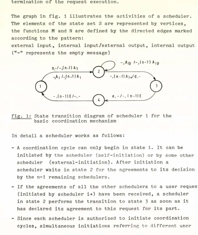
OPERÁCIÓS RENDSZEREK E L M É L E T E III. V IS E G R Á D I T É L I IS K O LA
ISBN 963 311 049 1 ISSN 0324-2951
Tanulmányok 69/1977.
Szerkesztőbizottság:
AR A TÓ M Á T YÁ S (felelős szerkesztő) DEM ETRO VICS JÁNOS (titkár)
FISC H ER JANOS, FR E Y TA M Ä S , G EH ER ISTVÁ N
G E R G E L Y JÓZSEF, G E R TLE R JANOS, K E R E S ZTÉL Y SÁNDOR PRÉKOPA AND RAS, T A N K Ó JÓZSEF
Felelős kiadó:
Dr VÁMOS T IB O R
M T A Számítástechnikai és Automatizálási Kutató Intézet MTA Számítástudományi Bizottsága
Konferencia szervező bizottsága:
A R A TÓ M ÁTYÁS (elnök) K N U T H ELŐD (titká r)
V A R G A LÁSZLÓ
Készült:
az ORSZÁGOS MŰSZAKI ES DO KUM EN TÁCIÓ S KÖZPONT házi sokszorosítójában
F.v.: Janoch Gyula
- 3 -
A konferenciát a ’’Számítástechnika tudományos kérdései” c.
többoldalú akadémia együttműködés keretében rendeztük.
Конференция была проведена в рамках многостороннего сотрудничества академий
социалистических стран по проблеме
"Научные вопросы вычислительной техники"
Conference was held in the frame of the multilateral cooperation o f the academies of sciences o f the socialist countries on Computer Sciences.
TARTALOMJEGYZÉK J.A. Kogan
Lapozáai algoritmusok egy hierarchikus osztálya .... 7 P. Schumacher
Számítógéprendszerek modellezése szimulációs hálók
kal ... 14 Pabók J., Hermann G., Rácz Zs.
OSCAR ... 31 В. Wolfinger, О. Drobnik, E. Holler
Decentralizált hálózatok tervezése és szimulációja . 49 I.V. Szergijenkó, I.N. Paraszjuk
Egy alkalmazási programcsomag-osztály ütemezési al
goritmusáról ESZR számitógépekre ... 64 Bárdossy Dániel, Iványi Antal
Lapozási algoritmusok tulajdonságairól ... ... 79 Győr у György
Diszkrendszerek használatának újabb módjairól .... . 95 Knuth Előd
Folyamatok dinamikus rendszerének koordinálásáról .. 102 W. Cellary
Erőforrás lekötési politikák a nempreemptiv esetben 107 Gáspár András, Visontay György, Csáki Péter
Kvázi parallel taskrendszerek ... ... 120 G. Bergholz
Real-time folyamatok analizise ... ... 141
- 5 -
CONTENTS
Ya.A. Kogan
A class of hierarchical paging algorithms ... 7 F. Schumacher
Modeling and simulation of computer systems with
simulation nets ... «... 14 J. Fabók, G. Hermann, Zs. Rácz
O S C A R ... 31 B. Wolfinger, 0. Drobnik, E. Holler
Design and simulation of decentralized control
structures for reliable distributed systems ... 49 I.V. Segiyenko, I.N. Parasyuk
On the scheduling for a class of program packages
for Ryad machines ... ... . 64 D. Bárdossy, A. Iványi
On some features of paging algorithms ... 79 Gy. György
Some recent developments in disk systems utilization 95 E. Knuth
Coordination of dynamic systems of processes ... 102 W. Cellary
On resource allocation polices in uniprocessor
systems with nonpreemptible resources ... 107 A. Gáspár, Gy. Visontay, P. Csáki
Quasi parallel task s y s t e m s ... ... ... 120 G. Bergholz
Analysis of real-time processes ... 141
- 6 -
СОДЕРЖАНИЕ Я.А. Коган:
Об одном классе алгорифмов виртуальной памяти ... 7 Ф . Шумахер :
Моделирование вычислительных систем с помощью
имитационных сетей ... 11 Ю. Фабок, Г. Херманн, Ж. Рац:
ОСКАР ... 31 Б. Волфингер, О. Дробник, Е. Холлер:
Проектирование и имитация децентрализованных
сетей ... 49 И.В. Сергиенко, И.Н. Парасюк:
Об организации вычислительного•процесса в одном
классе пакетов прикладных программ на ЕС ЭВМ ... 64 Д. Бардошши, А. Ивани:
О некоторых свойствах страничных алгоритмов ... 79 Дьёрдь Дьёри:
О новых методах использования дисковых систем .... 95 Э, Кнут:
Координация динамических систем, процессов ... 102 В . Целлари:
Политика завязывания ресурсов ... 107 А. Гашпар, Г. Вишонтаи, П. Чаки:
Псевдо - параллельные системы ... 120 Г. Бергольц:
Анализ процессов, работающих в реальном масштабе
времени ... 141
A CLASS OF HIERARCHICAL PAGING ALGORITHMS
Ya.A. KOGAN
Institute of Control Sciences Moscow, USSR
A paged virtual memory has become a common feature of large modern operating systems. The costs associated with paging have led to a great deal of re
search on the paging algorithms. Almost all paging algorithms discussed in the literature and implemented in computer systems are local, since they retain in main memory only those pages that were used recently in some sense.
FIFO, LRU and Working Set are well known examples of such paging algorithms, which differ by the definitions of the set of most recently used pages.
With local paging algorithms the rerely requested pages may replace those of real working set of a program. In this paper we define a class X of hierarchical paging algorithms a member of wich with properly selected para
meters will be free of this disadvantage.
For paging algorithms of the class X the contents and ordering of the pages in main memory may be regarded as the state of the device.
Let В = (i^, . . . , ) represent the memory state at time t . To define a paging algorithm*" we should indicate how Bt is transformed
into В . t+l .
h
Let В = U M, where h is a parameter of the classX, the intersection t k=l *
for al к ^ j and
*1
“h
(i ,i 2 •••» i lm ) * M 2 (1 2i»122*
1 h
(lh l ,1h 2 ’ 1hm h ) ; h < 1, U r n . i=l
2m.
m.
It should be noted that some of M i may be empty. Now we introduce the following parameters:
It should be noted that some of may be empty. Now we introduce the following parameters:
u is the maximal size of the set of the set M , i.e. Im I < u
T T * T — ч
T=1.... h.
is the time that a page nay retain in M^., r*l, h, without referencing to it. The time is measured, as usual in seconds of process (virtual) time. We suppose that _> T-,> . .. T^.
t is the time since the last reference to tha page i E M ,
T F 6 т т t
T=l,..., h. We shall use also some additional parameiers the essence of which will be clear from the following definition.
Definition. Let X . be the page that is referenced at time t+1.
^ ^ . A
For a paging algorithm A € % the transformation rules В -+ Bt+^ are defined by the following steps.
Step 1. Remove from those pages that are not referenced within the interval ft+l-T , t+11 , T=1 ..., h .
- 8 -
Step 2. Denote by
(it1* *•., i ,) The
Tm L ordered set of pages which is left in M T= 1,.
T> . . ,h , after Stepl l.
Let
В » = (м’»М*
t+1 1 2 ...V -
Step 3. The memory state Bt+j differs from
Bt+1 i) only by
if V f V i • ii) only by Mt ,l<T<h, if
* t . l £ Mt4d t where D
T is a fixed subset of M , 2<T<h
T --- , and D^= 11 , iii) only by M , and M
1 T i£ DT where D
T defined in ii) and 2 < t t< h.
Step 4. Definition of Вt+1
9
Let 0 <ct^__<L and T = 1 ... h, be additional parameters of the paging algorithms A € % .
In case i) Bt+1 = (M*, , Mjj)
where
mV =
a t+l’ \ 1 ' “
’ 4 *
if W h and ^ < y h h
(Jtt+1* \ l ” '
■ Ч - 1’
if fch >oth T h or m h = u
In case ii)
t + 1 = (MJ, M ’
T - l ’ M" m; +i * V where for X ., = i
t+1 TS M ’T
^ T S , 4 l * '*** \s-l* 4 s + l*
In case iii)
if £ < < m* . T — T
V i ■ <Mi ...Mx - 2 ,MT - i * t * ML r •••> V where for % , = i
t + 1 TS
M" . т-1
and
(iTS> •»и H .1 r-4
1 f-lm*
T-l
if t 1 < et ,T ,
t -1— т-l T-l and m* ,< 1 1 -, T-l MT — 1 (iTS> 4-11* T-lm’ )
T-l
if t X >01 , T .
T -1 т-l T-l or m ’ = y , T-s иТ-1
V i Tl, i 1 » 1 .... l ,) if t , <ot t T ,
TS-1 TS + 1 Tin’ т-1— т-1 т-1 T
M"= J and m ’ , < у ’ л
T l т-1 т-1
L (lT-lm^_1 * 4 l ... 1t s-1 » Ч в + 1 ... Ч т ^
10
if t , > a ,T , т-1 т-1 т-1 or ш ’ , = у
т-1 т-1
Thus in а general case a paging algorithm A e X depends on the following parameters; h , 5h numbers y ^ , T^, t^, oi^. and 8,^ and h-1 of the subset D .
T
The class X of hierarchical paging algorithms contains a number of algorithms of practical and theoretical interest.
With T ^ * ^ * . . ’T^”00 and DT=MT »2ji T ^ h , we h a v e the class H
introduced in [1]. There known paging algorithms, FIFO, LRU and CLIMB, are extremal members of H which are obtained for h=l, 8.^=y^; h=l, 8^=1 and у^=...=уп« 1 respectively. With h=l and y^=°° we have a Modified Working Set paging algorithm C2I which transforms for a^=l in a Working Set paging algorithm.
The class % extends considerably the control possibilities as compared with the class H . To demonstrate the advantages of the classé» let us consider a simplest Markov model of program behaviour. For this model
. r Pi (l-qj
P t * t+ 1 - i - J
I q.+(l-q.)p.^ i V ni ' * i j И j=i
(1)
where i,j=l,2 n
n 0 < < 1, p. 0 and
D e n o t e by F^iA) the long-run page fault rate for the paging algorithm A and main memory size m . Using the correspondence between the Markov model (1) and the independent model pbtainde form (1) if q^*=...qn=0, we can prove that for a simplest Markov model of program behavior
n
F (LRU) - F° (LRU) / S P-)°i l - l
(2)
- 11
where F (A) denotes the long-run page fault rate for the independent
m ”1
model and iK = (l-q^) is the so called page duration.
Furthermore if U^=...=Un= U , then for any A € H
F (A) = FU (A) / u.
m m
Let E = m and consider the Markov model (1) with the parameters pr...=pm=p, Pm+1 = a , pm+2=...=pn=0, qi=...=qm =0 and qm+1 = q .
Suppose that a ->■ 0. and q 1. Then it is easy to show that for any A £ H
F (A) > F (LRU),
m — m
For example, with m=2 we have
lira F (CLIMB) / F (LRU) = 7/5; lim F (FIFO) / F (LRU) = 6/5.
a-4),q*l m m a-+0,q->l m
Now let us consider the paging algorithm A € X defined by the following parameters: h=2, т 1=т2= °°» y 1=sm —2 y2=2, D 2=i22‘ Then it: is easy to show that
~ n
sup CF (A) / (a / E p.U. )I
m . . l l
p,a,q i=l
is independent of m, while from III and (2) we have n
sup CFm (LRU) / (a / p.U.)I = 1+ E 1 /i
P.a.q 1 1 1 i—1
which is increasing logarithmically as m
Distribution-free results on algorithms of the class % may be obtained by the technique developed by the author in III.
On the case of an independent model of program behavior explicit expression of Fm (A) may be obtained for a number of paging algorithms A 6 % ,
For example, if °°, ^ = £ ^ = 0 , y2=£2=m-c , D2=i-21» then
- 12 -
n F (A) = I p 2.
га * i
1 л ~ . 1 • • • 1 .__ • . 1 1 •
с с+1 m j>=m+l j ш
where summation extends over all permutations of m distinct integers selected from (1,2,..., n).
1. Aven O.I., Boguslavsky L.B. and Kogan Ya.A. Some Results on
Distribution-Free Analysis of Pagaing Algorithms, IEEE Trans. Comput., vol. C-25, No.7, pp. 737-745, July 1976.
2. Smith A*J. A Modified Working Set Paging Algorithm,, IEEE Trans.Comput., vol. C-25, No.9, pp.907-914, September 1976.
REFERENCES
- 13 -
Dapozásl algoritmusok egy hierarchikus osztálya Кордап J». AV
A' dolgozat a lapozás! algoritmusoknak e g y olyan táp; osztályát vizsgálja, msly tartalmazza a leg
több ismert tipikus stratégiát.
Р Е З Ю М Е
Об одном классе алгорифмов виртуальной памяти Я.А. Коган
В работе рассматривается широкий класс алгорифмов, включающий большинство известных типичных стратегий.
.
Modeling and Sim ulation of Computer Systems with Sim ulation Nets
by
Franz Schumacher
G esellschaft fü r Kernforschung mbH, Karlsruhe D-7500 Karlsruhe, Postfach 3640, FRG
1. Introduction
The growing complexity of modern computer systems has made perform
ance evaluation re s u lts more and more d i f f i c u l t to obtain. One pop
u la r approach th a t has been used fo r evaluating proposed computer systems is d is c re te event sim ulation.
An e f f ic ie n t and g en erally known model description method does not e x is t in the sim ulation of d is c re te systems. E s pecially when simu
la tin g with SIMULA or SIMSCRIPT a complete descrip tio n of the simu
la tio n model w ill be the program i t s e l f .
The purpose of the paper is to introduce a method o f representation th a t is useful in constructing and evaluating a sim ulation model in a r e la tiv e ly small amount of tim e. The method is based on P e tri nets / 1 , 2/ and c arries on the a c t iv it ie s on P e tri nets performed by Nutt / 3 / . The method w ill be named simulation n e t, abbreviated s -n e t.
The s-n et system is a computer program fo r sim ulating s-n ets. The s-n et system has been implemented as a p re fix class in SIMULA.
1
- 15 -
In the follow ing an informal d e fin itio n of an s -n e t is given. The ap p licatio n of the modeling method and the sim ulation system to a queuing model of a computer system is shown.
2. D e fin itio n of a Sim ulation Net
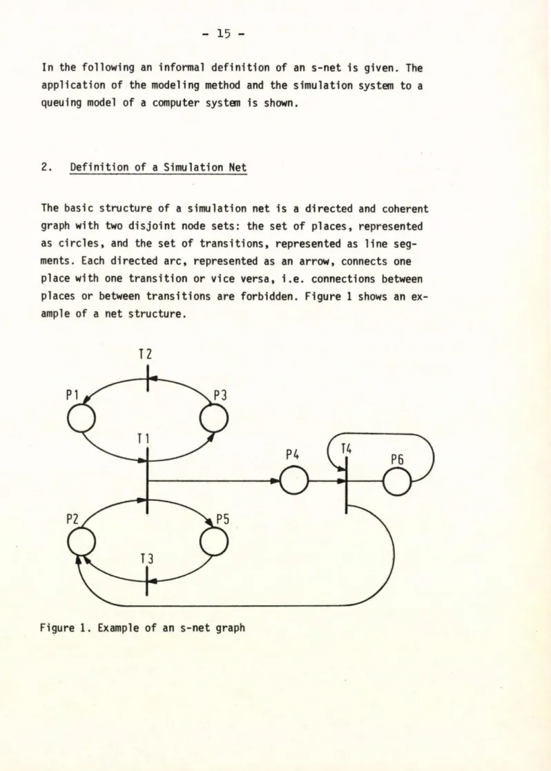
The basic stru ctu re of a sim ulation net is a d irected and coherent graph with two d is jo in t node sets: the set o f places, represented as c ir c le s , and the set o f tra n s itio n s , represented as lin e seg
ments. Each d irected a rc , represented as an arrow, connects one place with one tra n s itio n or vice versa, i . e . connections between places or between tra n s itio n s are forbidden. Figure 1 shows an ex
ample of a net s tru c tu re .
12
Figure 1. Example o f an s -n e t graph
16 -
An arrow from a place to a tra n s itio n means th a t the place is an input place of the tra n s itio n , e .g . PI of T1 in Figure 1; an arrow from a tra n s itio n to a place means that the place is an output place of the tra n s itio n , e .g . PI of T2 in Figure 1.
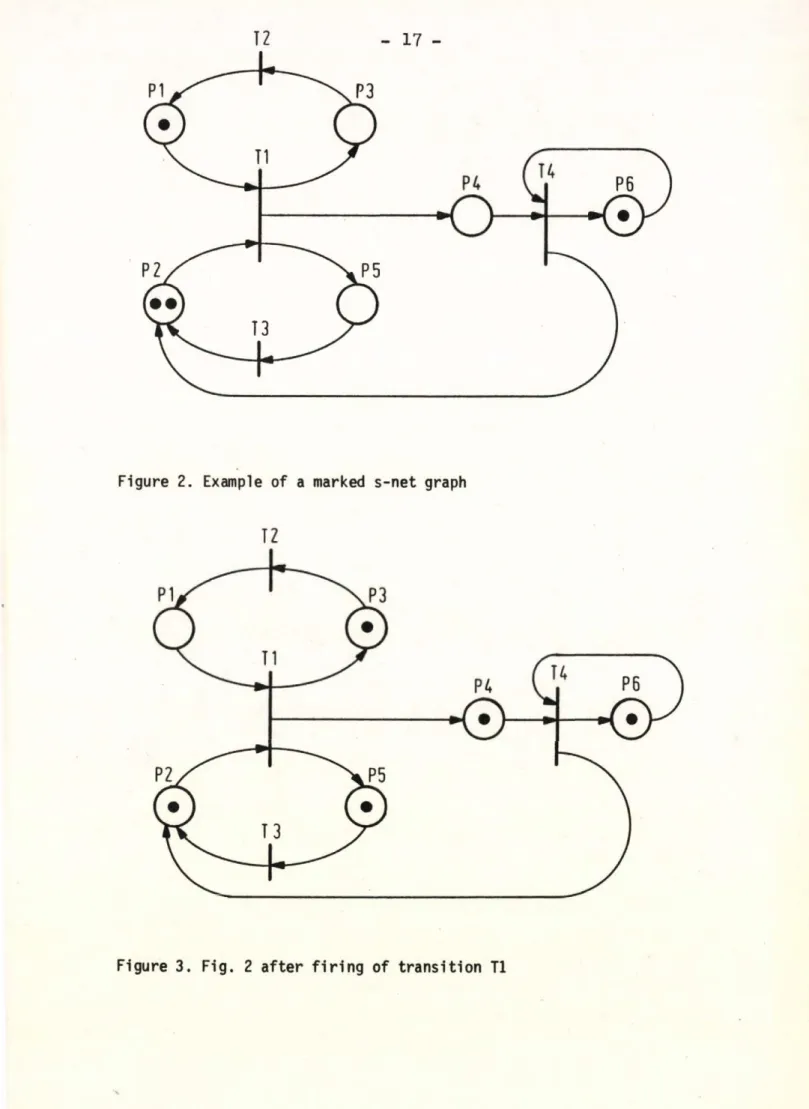
A place may be marked, i . e . a place may contain tokens, represented as dots. For example, places PI and P6 in Figure 2 contain one token each, and place P2 contains two tokens. Thus, the stru ctu re of an s-net is equal to the s tru c tu re of a P e tri net.
Every tra n s itio n possesses a so -c a lle d a c tiv a tio n scheme and tra n s itio n scheme. The a c tiv a tio n scheme of a tra n s itio n contains an integer number fo r every input place. A tra n s itio n is c a lle d ac
tiv a te d , i f the number of tokens on each input place is g re a te r or equal to the corresponding in te g e r number in the a c tiv a tio n scheme.
For instance, i f the a c tiv a tio n scheme of tra n s itio n T1 in Figure 2 is defined by
input place no. PI P2
number of tokens 1 2
then the tra n s itio n T1 in Figure 2 is a c tiv a te d .
The d e fin itio n of the tra n s itio n scheme is q u ite lengthy and w ill be given la t e r . Now a tra n s itio n scheme shall be defined by r e moving one token from each input place of an activated tra n s itio n
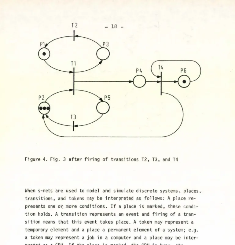
and by s e ttin g one token on each output place. This d e fin itio n is the tra n s itio n ru le in P etri n ets. The execution of the tra n s itio n scheme is c a lle d f ir in g of the tra n s itio n . E.g. the tra n s itio n T1 in Figure 2 is activated with the a c tiv a tio n scheme defined above and the tra n s itio n scheme can be performed. Figure 3 shows the net a fte r f ir in g of T1. I f a ll the a c tiv a tio n schemes of tra n s itio n s T2, T3 and T4 contain the number one, these tra n s itio n s can be fire d (s . Fig. 4 ).
12 17 -
Figure 2. Example of a marked s-n et graph
Figure 3. F ig . 2 a fte r f i r i n g of tra n s itio n T1
Figure 4. Fig. 3 a fte r fir in g of transitions T2, T3, and T4
When s-nets are used to model and simulate d is c re te systems, places, tra n s itio n s , and tokens may be in terp reted as follow s: A place re presents one or more conditions. I f a place is marked, these condi
tio n holds. A tra n s itio n represents an event and f ir in g of a tra n s itio n means th a t th is event takes place. A token may represent a temporary element and a place a permanent element of a system; e.g.
a token may represent a job in a computer and a place may be in te r preted as a CPU. I f the place is marked, the CPU is busy, e tc .
Every token and every place may possess parameters, e .g . token num
b e r, place number, etc.
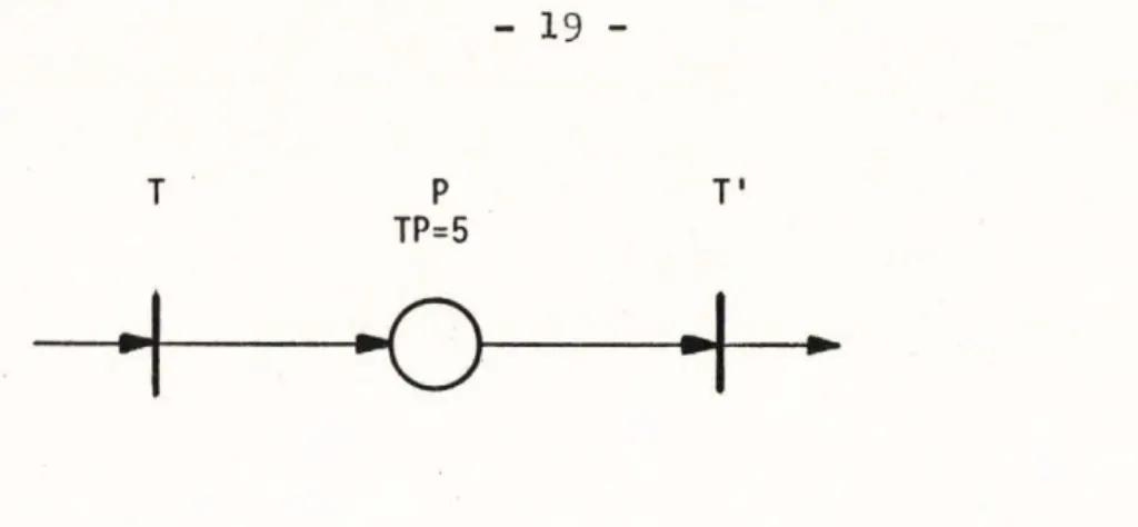
A so-called place time TP is a llo c a te d to a place. I f a token enters a place, i t is delayed by th is place by TP time u n its . E.g. i f the place time of a place P is 5 time units and i f a token enters place P a fte r fir in g o f T , then T' c a n 't be fire d before 5 time units:
- 19 -
T P
TP=5
T'
H—о—+-
The main ru le of the dynamic behavior of an s -n et says: I f a token enters a place P with place time TP, the a c tiv a tio n schemes of the output tra n s itio n s of place P, i . e . the tra n s itio n s fo r which place P is the input place, are c a lle d a fte r TP tim e u n its . I f the ac
tiv a tio n scheme of an output tra n s itio n y ie ld s the value tru e , i . e . the number of tokens on each input place is greater than or equal to the corresponding in te g er number in the a c tiv a tio n scheme, the a c tiv a tio n scheme c a lls the tra n s itio n scheme, i . e . the tra n s itio n f ir e s . I f a place is the input place of more than one tra n s itio n ( c o n flic t case), the a c tiv a tio n schemes o f the tra n s itio n s are called in the sequence of increasing tra n s itio n number.
The d e fin itio n of the dynamic behavior allows the modeling of in terru p ts and lo g ic al s tru c tu re s . The place time of place P2 in Figure 5 is in terru p ted by place P I, because tra n s itio n T' is ac
tiv a te d and fir e d a f te r fin is h in g of place time TP1.
T PI
TP1 = 5
T'
P2 TP2=8
Figure 5. Example of an in te rru p t structure
20
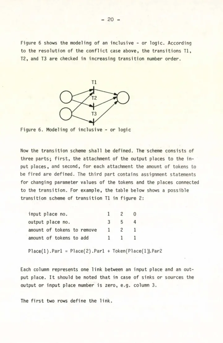
Figure 6 shows the modeling o f an inclusive - or lo g ic . According to the re s o lu tio n of the c o n flic t case above, the tra n s itio n s T l, T2, and T3 are checked in increasing tra n s itio n number order.
Tl
Figure 6. Modeling of in c lu s iv e - or logic
Now the tra n s itio n scheme s h a ll be defined. The scheme consists of three p arts; f i r s t , the attachment of the output places to the in put places, and second, fo r each attachment the amount o f tokens to be fire d are defined. The th ir d part contains assignment statements fo r changing parameter values of the tokens and the places connected to the tr a n s itio n . For example, the table below shows a possible tra n s itio n scheme of tra n s itio n Tl in fig u re 2:
input place no.
output place no.
amount o f tokens to remove amount o f tokens to add
1 2 0
3 СЛ 4
1 2 1
1 1 1
P la c e (l) .P a ri = Place(2) .P a ri + Token(Place(l)).Par2
Each column represents one lin k between an input place and an out
put place. I t should be noted th a t in case o f sinks or sources the output or input place number is zero, e .g . column 3.
The f i r s t two rows define the lin k .
21 -
The th ird row determines the number of tokens to be removed from the input places and the fourth row determines the number of tokens which are added to the output places. Under the tab le an assignment statement is shown which changes a parameter o f input place P I.
Two special cases give ris e to separate treatm en t, f i r s t , i f one in put place is connected to more than one output place, and second, i f an input place contains more tokens than tokens should be f ir e d . In these cases a se le c tio n must be made, e .g . random, f i r s t - i n - f i r s t - out (FIFO ), e t c . . Figure 7 shows an example o f a complete tra n s itio n d e fin itio n .
T
A ctivatio n scheme:
input place no.
minimum of tokens
1 2 3
1 2 4
Tran sitio n scheme:
input place no. 1 2 3
lower output place no. 4 5 0
upper output place no. 5 5 0
amount of tokens to remove 1 1 4
amount of tokens to add 1 3 0
token selectio n mode LIFO FIFO FIFO
place se le c tio n mode RANDOM
Figure 7. Example o f a tra n s itio n d e fin itio n
го о ст> a> о
22
3 . The S-Net System
The s-net has been implemented as a p re fix class in SIMULA. The p re fix c la s s , c a lle d SIMULATION NET, consists of the follow ing parts:
s-net sim ulation part
selection procedures: place time - token - place measurement procedures
te s t of the model
input o f model d e fin itio n output procedures:
model - re s u lts - histogram - trace - e rro r - warning trace procedures
reset procedures s ta rt sim ulation main lin e
For a more d e ta ile d description o f the system see / 4 , 5 /.
Now, the user has only to d e fin e his s-net model on input d a ta , i . e . matrices which define the net s tru c tu re , and then the sim ulation goes on. The standard output y ie ld s c h a ra c te ris tic s fo r every place re la tin g to the maximum, minimum, average, variance of number and duration of tokens on a place, i . e . queue length, w aiting tim es, busy period, e t c . . Special routines have been implemented which support the user of the s-n et in te s tin g , data analysis e t c . , e.g . tra c e , histogram, reset and c le a r procedures.
- 23 -
4. An Example
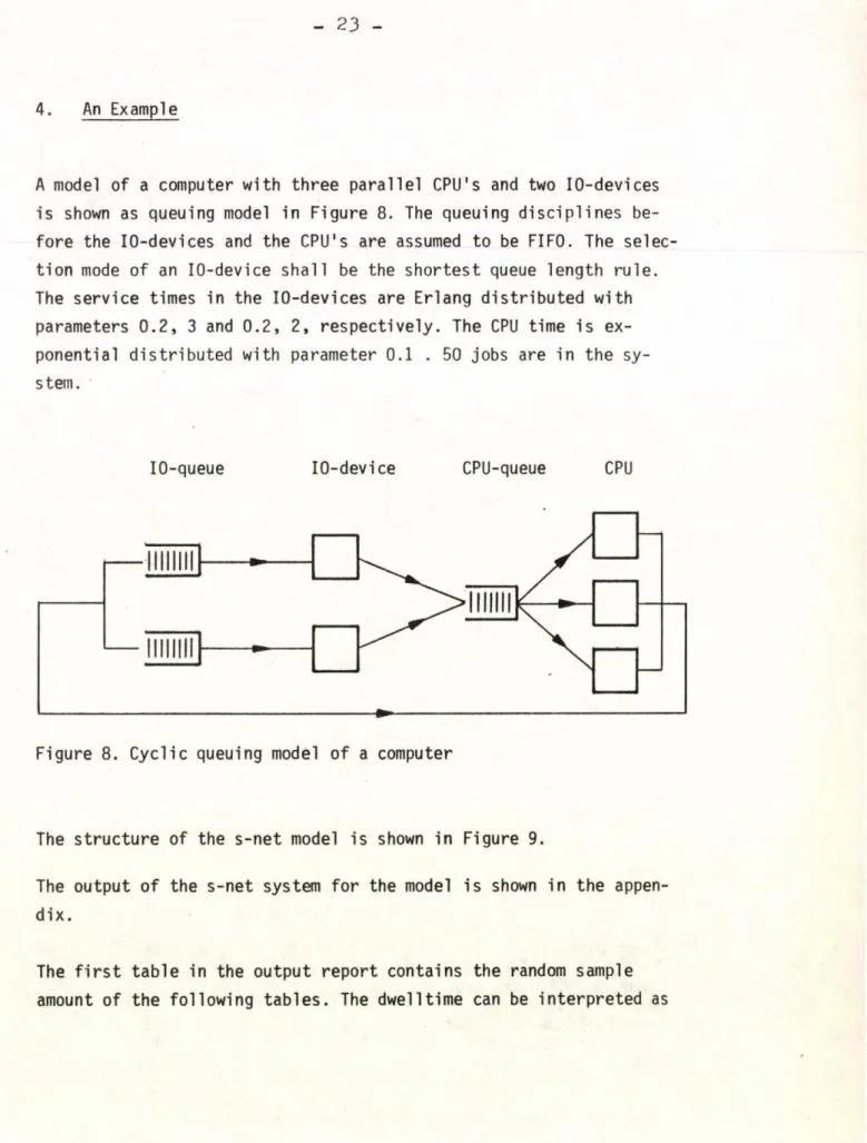
A model of a computer with three p a ra lle l CPU's and two 10-devices is shown as queuing model in Figure 8. The queuing d is c ip lin e s be
fo re the 10-devices and the CPU's are assumed to be FIFO. The selec
tio n mode of an 10-device s h a ll be the shortest queue length ru le . The service times in the 10-devices are Erlang d is trib u te d with parameters 0 .2 , 3 and 0 .2 , 2 , re s p e c tiv e ly . The CPU time is ex
ponential d is trib u te d with parameter 0.1 . 50 jobs are in the sy
stem.
10-queue 10-device CPU-queue CPU
Figure 8. C yclic queuing model o f a computer
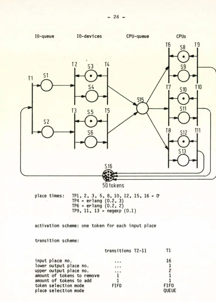
The stru c tu re of the s-n et model is shown in Figure 9.
The output o f the s-net system fo r the model is shown in the appen
d ix .
The f i r s t ta b le in the output report contains the random sample amount of the follow ing ta b le s . The dwelltim e can be in te rp re te d as
24
IO-queue IO-devices CPU-queue CPUs
place tim es: TPI, 2 , 3 , 5 , 8 , 10, 12, 15, 16 = O’
TP4 = erlan g (0 .2 , 3) ТРб = erlan g ( 0 .2 , 2) TP9, И , 13 = negexp ( 0 .1 )
a c tiv a tio n scheme: one token fo r each input place tra n s itio n scheme:
input place no.
lower output place no.
upper output place no.
amount of tokens to remove amount o f tokens to add token s e le c tio n mode place s e le c tio n mode
tra n sitio n s T2-11 T1 16 1 2
1 1
1 1
FIFO FIFO
QUEUE
Figure 9. s -n e t of the c y c lic queuing computer model
waiting time (place 1 ) , id le time (place 3) or service time (place 13). The values in the tab le 's ta tis t ic s of tokens' represent e.g.
queue length (place 1) or throughput (place 6 ).
The computation time ot the example was about 30 sec CPU-time on IBM 370/168. Thus, the average computation time of one tra n s itio n f i r i n g , i . e . one event, was about 2 msec.
3. Conclusions
S-nets can gen erally be applied to modeling and sim ulation o f any d is c re te system. The advantages are manifold:
Graphical arrangement, which means c le a r representation of system elements and co n strain ts.
Laborious programming work can be avoided almost completely and thus the v e r ific a tio n of a program as w e ll.
The model d e fin itio n in terms of an s -n et is comprehensive and can serve as a platform fo r discussions w ith involved persons, e .g . managers, team members, e t c ..
The s-nets are easy to le a rn , because they can be defined on few sheets of paper (no voluminous handbook).
Simulation studies can be performed by people who are not fa m ilia r with programing languages.
The major disadvantage lie s in the d i f f i c u l t y to survey s -n et model of very complex systems.
Future possible tasks are the implementation o f a display in te r face ( lig h t pen), the connection with descrip tio n methods used in continuous sim ulation (e .g . DYNAMO), and improvements o f the s-net
26 -
i t s e l f , e .g . representation o f a model a t d iffe r e n t le v e ls of d e ta il (topdown approach) in order to elim inate the disadvantage mentioned above.
Acknowledgement
I want to thank Mr. R. Ramöller fo r implementing the s -n e t in SIMULA and fo r many discussions.
/ 1 / C.A. P e tri Kommunikation m it Automaten.
D is s e rta tio n , U n iv e rs itä t Bonn, 1962.
/ 2 / A.W. H o lt e t a l. Inform ation system theory p ro je c t
( f i n a l re p o rt). AD 676972, P rinceton, 1968 / 3 / G.J . Nutt Evaluation nets fo r computer system
performance a n a ly s is . F a ll J o in t Computer Conference, 1972.
/ 4 / F. Schumacher The S-Net System User's Manual.
In te rn e r A rb e its b e ric h t, GfK-IDT-263-02, K arlsruhe, 1976.
/ 5 / R. Ramoeller Implementierung eines e rw eiterten P e tr i- netzmodells zur Simulation d is k re te r Systeme.
Diplom arbeit, U n iv e rs itä t K arlsruhe, 1976.
STATISTICGFPLACES **********************
27
Appendix: Output Report of the S-Net System for the Example in Figure 9.
a *#
3 # о о
о о о о о о
• • о о о о о о
3 1 ос 1Г» ce 00 Ю Ю 4545CMCM< r »J CMCM 1
a 1 со O 'CO COa O 'If . O O CM CM 00 00 1 V f I f 4 ocO '—1 O O O O 45 O m г - O
» - 1 r» r-4 r - r - —4 •*4 O ' O ' O O O O O 'O ' UJ 1 O —4 CO O —4 4 ) O < r о 4 ) O O ' 1Г» O
3 1 ■—4 •—4 — 1 —4 •—4 4-4 •H —• —1 CM CM C i 1 42 sO O ' CM O «9- O O ' O r - CM O
о 1 < r f • • • • • • • • • • • • • •
1 a r 1 IT \ ir> O 6Í-m in O O O 6 0 O 'r - O
О О О —< О —< О . ' O H t r n
O O r N O ' O O ' t O O ' O K l O O О О О СГ N 0 0 0 ^ 0 0 ^ 0
о о о —> o a o o o o o o > t - o
O O O O O O O O O O O O i r . о
« О С О О И 1 Л > 0 0 ( М О и О и О О f C c O' t ^ O ' t O - ' O O ' OH On H M ( V « r ^ N 0 f ,> 0 ( M 0 H l f ' 0
no-O'ONX'CCPOr’ O^O'O m го —• —1 г- см Г- f- tri —«
CM
I
I I
I( M < f < t ^ i ^ c u O ' C o s u o c o o I ' O o r a O ' O C O O f C . O H O t v j N o I c o ^ o t c o i A o ^ o M O i f M T o
I • * • • • • • • • • • • • •
I U > 4 > C M f v O O r o o C ' 0 0 0 0 ' f M O
I __I _I
1
1 Ш V а >-UJ>- Ul >■ Ш >•
Ш 1 3 CO3 l/l3LO 3C/7 3 CO Ui
1 O3 O 3 CJ 3 O 3 a 3 T.
< 1 4— CO 6—4en CO —4rr *—•CO Ш <
Z 1 3 Z
Ш 1 •—4r - tCM (M O LU
O 1 UJ UJ UJui m m m m en ro U» > *
«I 1 Ш UJ O O OO 1 1 1 1 1 t3 O * <
-J 13 3 1—46-4— 4 4—4CM CMCMCMCM CMUj Ш * 3 a 1LU UJ> > > > 1 » » 1 1 13 a T . * а
• 3 3 UJ UJ IL Ul —J i—4—4 —-4 »4a t—4 6-4 #
1CJ O O O O O i 1
1 ! 1 1 1 1 1 3 3 3 3 —1 3 3 3 3 * 1O O O O c O O. O. а CLa a. aа 3 * 1
1 *“ ■O
O LJ U O O O LJ U1 *
~x *
—<r«jm^u'4caocr'0—<гч|ош>о
U- *
о ** l_> *
—< * h- * Vi *
—' *
LU > LUV U J> UJ> LU >- 3 CO3 CO3 CO _J CO 3 1Л CJ 3 O 3 O 3 c 3 CJ 3
—4CD6—C04— m t-4 CO 6— a 3
•—4 f—4 CM «M O
LU a 'U Ja r o m m CO m r i LU >
LUU JO O O O ! 1 1 1 1 1 3 L J 3 3 4— •—i 6— »-4 CM CMr\JCM CMCM LU U JLU > > > > 1 1 1 1 1 1 3 c 3 3 UJ ш U Ja •—4•—4 —~4 1—4—4 —4 O 6—4
O O 3 c <r O 1 t
1 1 i t 1 i 3 3 3 3 3 3 3 3 O O c? O о O a a 0 a a a a a
u U O L J O O L JO
- M r v t i n o t o a - ü H i N i m m >c UJ *
T *
- * CVJ m ^ i f ,
a *
O-OUEUE0.3971.60326.367C.006 O-OUEUE0.6123.62779.9611.016 O-DEVICEKICLE)0.8782.22316.6110. 188 n-DEVtCEl(BUSY) 0.123C.92319.2660.000 0-DEVICE2UCLE) 0.6162.08326.7660.026
6 I O - D E V I C E 2 ( BUSY I 0 . Э8А 2 . 9 7 A 7 7 . 6 9 5 0 . 0 0 0
e CPU 1 - 2 - 3 I I D L E ! 0 . 9 9 9 A . A 9 9 7 8 . 3 1 2 O.OOA
9 CPU 1 - 2 - 3 I BUSY 1 0 . 0 0 0 0 . 0 0 0 0 . 0 0 0 0 . 0 0 0
10 CPU 1 - 2 - 3 1 I C L E I 0 . 9 9 7 A.AOO 7 3 . 2 9 1 0 . 0 3 9
11 CPU 1 - 2 - 3 (BUS Y) 0 . 0 0 0 0 . 0 0 0 0 . 0 0 0 O.COO
12 CPU 1 - 2 - 3 ( ID L E 1 1 . 0 0 3 A . 25 1 5 A . l l 1 0 . 0 0 8
13 CPU 1 - 2 - 3 (B U S Y! 0 . 0 0 0 0 . 0 0 0 0 . 0 0 0 0 . 0 0 0
15 CPU-OUEUE o . c o o 0 . 0 0 0 0 . 0 0 0 0 . 0 0 0
16 C P U - 1 0 CYCLE 1 . 0 0 0 2 .A A 1 2 8 . 0 0 A O.OOA
I S T IC OF TOKENS I * * * * * * * * * * * * * * * * * * * *
ACENO PLACENAME AVERAGE S T A N O .D E V I A T IO N MAXIMUM MINIMUM
1 I O-QUEUE 1 . 0 0 1 1 . C 9 1 6 . 0 0 0 0 . 0 0 0
2 IO-QUEUE 0 . 6 A 7 0 . 9 7 9 6 . 0 0 0 c . o o o
3 10—D E V T C F I I I D L E ) 0 . 1 2 3 0 . 3 2 8 1 . 0 0 0 0 . 0 0 0
A 1 0 - D E V l C E K B U S Y ) 0 . 8 7 7 0 . 3 2 8 1 . 0 0 0 0 . 0 0 0
5 IO - D E V I C E 2 I I D L E ) 0 . 3 8 A С. A86 1 . 0 0 0 0 . 0 0 3
6 IO - O E V I C E 2 ( BUSY) 0 . 6 1 6 0 . A 8 6 1 . 0 0 0 0 . 0 0 0
8 CPU 1 - 2 - 3 ( I D L E ) O.COO 0 . 0 0 0 1 . 0 0 0 c . o o o
9 CRU 1 - 2 - 3 (BU SY) 1 . 0 0 0 0 . 0 0 1 1 . 0 0 0 0 . 0 0 0
10 CPU 1 - 2 - 3 ( 1 DLF ) 0 . 0 0 0 0 . 0 0 0 1 . J 3 0 0 . 0 0 0
11 CPU 1 - 2 - 3 (B U S Y) 1 . 0 0 0 0 . 0 0 1 l . 0 0 0 0 . 0 0 0
12 CPU 1 - 2 - 3 ( I D L E ) 0 . 0 0 0 0 . 0 0 0 1 . 0 0 0 0 . 0 0 0
13 CPU 1 - 2 - 3 (B US Y) 1 . 0 0 0 0 . 0 0 1 l . 0 0 0 0 . 0 0 0
15 CPU-OUEUE АЗ.ЯАА 2 . A 3 7 A 7 . 0 0 C 3 3 . 0 0 0
16 C P U - I O CYCLE 0 . 0 0 0 0 . 0 0 1 2 . 0 0 0 0 . 0 0 0
PATHS
«•ж****
FROM PLACE 16
U N T IL PLACE 15
AVERAGE 1 0 . 5 3 5
S T A N D .D E V IA T IO N 6 . 9 1 2
MAXIMUM
A 3 . 3 5 0
MI N I MU M 0 . 3 0 A
I
! 00ro I
PATHS
*******
FROM PLACE U N T IL P U C E AVERAGE S T A N D .D E V IA T IO N MAXIMUM MINIMUM
16 16 1 6 7 . 9 1 8 2 5 . 5 2 5 2 6 1 . 3 0 9 1 Û A . 3 0 9
I Г\0 VD
I
- 3 0 -
Számítógéprendszerek modellezése szimulációs hálókkal
F. Schumacher
A dolgozat egy a Petri-hálókon alapuló módszert ismertet számítógéprendszerek működésének leírására, ismerteti annak megvalósítását SIMULA osztályként, és bemutatja módszerének alkalmazását.
М о д е л и р о в а н и е в ы ч и с л и т е л ь н ы х с и с т е м с п о м о щ ь ю и м и т а ц и о н н ы х с ь т е й
Ф . Ш у м а х е р
Р а б о т а з н а к о м и т ч и т а т е л я с н е к о т о р ы м м е т о д о м о с н о в а н н ы м н а с е т я х П е т р и д л я о п и с а н и я р а б о т ы в ы ч и с л и т е л ь н ы х с и с т е м . В с т а т ь е о п и с ы в а е т с я т е к ж е о с у щ е с т в л е н и е м о д е л и р о в а н и я , к а к к л а с с
и р п р и л а г а ю т с я п р и м е н е н и я м е т о д а .
OSCAR
Operating System for Computer Aided Design’s Realization.
J. Fabók, G.Hermann, Zs.Rácz
Computer and Automation Institute of Hungarian Academy of Sciences
INTRODUCTION
The paper describes an automated workshop of special purpose machines controlled by a minicomputer. This workshop is
dedicated to design, produce and test printed circuit cards and electrical equipments.
The information flows in the system in two ways. The descrip
tion of the object to be produced can be given in a pretty formal way to a midicomputer - in this case a CDC 3300 - where it is processed by a special program package and
forwarded either by a communication line or by hand through a punched tape. The other way is to produce these data in a very primitive language by the designer and give it directly to the minicomputer. Therefore there must be a possibility to check those descriptions for correctness, modify it if
necessary, check it again and so on in an interactive way.
The information, produced in either way and stored in the library, is considered a data set from the aspect of the OS, but for the special purpose machine it is a program,
prescribing its action. This paper deals with the OS, so the library files will be referred to as data.
The operation of the workshop is controlled by an operator sitting before a keyboard of a teletype or a display. It is her duty to initialize all works to be done concerning both the production and the interactive design process. This is performed by programs and by the OS whose action is pretty predetermined.
32 -
Taking into account the requirements to be met by a so-called general purpose OS and by this one, you may conclude that this special OS, providing these facilities^ is an extended subset of the "general purpose" OS.
We decided to build up taylor made system, i.e. soma well known facilities had ueen left out /e.g, the possibility of extension or modification of computer programs/, and on the other hand new ones corresponding to the actions to be per
formed were introduced.
INTEGRATED SYSTEM
' " ■— - — T - - ■ I ■ -n I I I.
The integrated system developed in our Institute is a complex of hardware and software and its scheme is outlined in fig.l.
Integrated system fig.l.
33 -
The design is always the duty of the CDC 3300 and the output which is a technological description of the object in the
alphanumerical direct description language must be processed by postprocessors to get the data called control tape format digestable for the special purpose machine. Postprocessing may take place in either computer. The last phase of the
process, i.e. production, documentation and test takes place in an automated workshop. In the following, in order to
distinguish the electrical ewuipment to be designed and pro
duced from the equipment operating in the workshop, the former group will be referred to as "equipment" and the latter as
"dedicated machines" or simply "machines". Using the control tape as an input, the machines are able to work off-line, too.
The work in the workshop takes.place automatically, controlled by a minicomputer R-10 made in Hungary. On-line, the machines can operate on the basis of both the numeric control tape format and the direct description, called in the following symply data files.
FUNCTIONS OF THE WORKSHOP COMPUTER
The tasks of the workshop computer are the following:
1. Establishing information flow between the computer and the machines, which means to operate the machines and collect in
formation from them.
Ope-rating the machines supposes a two way connection between the computer and the machines. The computer sends the dedica
ted machine control bytes or normal data bytes. A control byte is an instruction to the machine itself, /for instance:
start, stop, send status message, etc./ Normal data bytes are parts of the numeric control tape format. If the production takes place on the basis of the direct technological descrip
tion , the conversion to the control tape format is performed real-tima.