Assessment of the Nanohardness of a-SiC: H Film by Cyclic Nanoindentation
Daniel Tischler
*, Marie Válová
*, Ivo Štěpánek
*** CTU in Prague, Faculty of Mechanical Engineering, 167 06, Prague, Czech Republic, E-mail: daniel.tischler@fs.cvut.cz, marie.valova@fs.cvut.cz
** University of West Bohemia, Veleslavinova 11, 301 14 Plzen, Czech Republic, E-mail: ivo.stepanek@volny.cz
Abstract: Due to very little depth of indent, the cyclic nanoindentation test is used for nondestructive testing of thin films of amorphous hydrogenated silicon carbide (a-SiC: H).
We prepared the films, containing various volumes of hexamethyldisiloxane (0.6 g/h and 1 g/h), onto stainless steel substrates by Plasma Enhanced Chemical Vapor Deposition technique. In this paper, the mechanical properties, especially nanohardness, are assessed by the cyclic nanoindentation test. We found out that higher volumes of vapors of Hexamethyldisiloxane cause increases in the nanohardness and thickness of the prepared film.
Keywords: cyclic nanoindentation; a-SiC: H thin film; hexamethyldisiloxane; PECVD
1 Introduction
Amorphous hydrogenated silicon carbide (a-SiC: H) coatings of a thickness of a few micrometers have been applied onto optoelectronic, photovoltaic [1] and dielectric diffusion barriers, and at present time they are a promising possibility for tribological applications in the mechanical and aeronautical industries [2].
The cyclic nanoindentation test is a very useful tool for measuring and evaluating nanohardness. The cyclic nanoindentation measurement is an advanced technique which derived from the nanoindentation technique. Due to the small mass of load used (e.g. 0.1 mN), which resulted in a very thin layer of the indent (about 1 μm), the cyclic nanoindentation test can be categorized as a nondestructive test. The little load of the indenter and progressive loading (and unloading) has the following advantages; the ratio of the depth of the indent to the depth of the thin layer is easy to maintain, and it is possible to study both the running of multilayer, sandwich and gradient systems and the running of degradation process from a deep profile. The measurement can be taken in a very small area. The
measurement can be taken directly on the thin layer-substrate systems. The changes in characteristic in the substrate interface can be evaluated. The hardness can be measured during the load and unload directly. The plastic and elastic deformation ratio can be determined. The correlation between the applied load and the depth of the indent is investigated by the measurement of the hardness. During the measurement, the depth of the indent is monitored at the load and unloads.
From the so-called indentation curve, the correlation between the load and the depth of the indent, the hardness and other mechanical values can be obtained (e.g.
Young’s module, fracture toughness of brittle materials), as well as can be information about the plastic and elastic deformation ratio, etc. from the whole load cycle. Most frequently the Vickers sharp diamond quadrilateral pyramid or the Berkovich trilateral pyramid is used as an indentor for the hardness evaluation.
Both the plastic and elastic deformations originate during the indentation of the indenter into the substrate. Only the nonreversible plastic deformations are preserved after unloading, so the plastic and elastic deformations can be distinguished [3].
In the experimental study, amorphous hydrogenated silicon carbide coatings (a-SiC:H) were prepared using the PECVD technique throughout the decomposition of hexamethyldisiloxane, which was diluted by a mixture containing vapors of argon (Ar) and methane (CH4). The effect of hexamethyldisiloxane volume on the mechanical parameters of the deposited films is investigated and discussed. A comparative study has been carried out with the cyclic nanoindentation test under the same measurement conditions.
2 Experimental
2.1 Preparation of the Samples
Amorphous hydrogenated carbon films (a-SiC:H) were deposited onto a stainless steel substrate using plasma enhanced chemical vapor deposition (PECVD), which is described elsewhere [4] .The samples (size 20 mm in diameter × 5 mm in thickness) were polished to a surface roughness of Ra = 0.02. The samples were cleaned in an ultrasonic bath containing isopropylalkohol for 10 minutes and instantly put on an electrode of a plasma-chemical reactor. In order to remove any remaining impurities (including oxygen) and to activate the surface of the used samples, argon plasma precleaning was applied for 15 minutes (Ar: 60 sccm/min, 15 Pa). The mixture of Argon (Ar) and Methane (CH4) was diluted by vapors of hexamethyldisiloxane in order to form a-SiC: H layers at work pressure 10 Pa in plasma immersion. Details are in table 1. The mentioned thickness was investigated after the test. The process gases as well as the vapors of
hexamethyldisiloxane were controlled bymass flow controls and the pressure was controlled using a butterfly valve. The working pressure (20 Pa) of the deposition processes was kept constant.
Table 1
Details of depositing parameters
2.2 Nanoindentation and Cyclic Nanoindentation
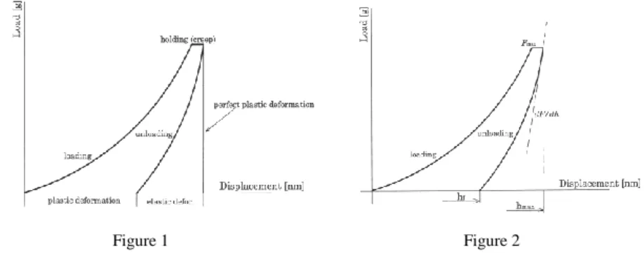
The cyclic nanoindentation was derived from the conventional nanoindentation technique. In the first step, the tip is pressed into the material, resulting in indistinguishable elastic and plastic deformation. It is shown that the loading part of the curve is a combination of both elastic and plastic deformations, while the unloading curve is largely dominated by elastic deformation (Figure 1).
Figure 1 Figure 2
Nanoindentation curve Nanoindentation curve. hf = depth after unloading; hmax = depth at maximal load Fmax
Then the tip is held at the maximum force, resulting in creep of the material under the tip. In the third step, the performed unloading leads to elastic recovery of the material. Usually, each indent requires 15 seconds to several minutes, representing a compromise between a desired quasi-static strain rate and the thermal drift of the instrument (possibly below 0.1 nm/second). This device is load-controlled, and linearly increasing and decreasing loading protocols were therefore applied. The loading rate corresponds to:
Samples Argon cleaning
HMDSO [ g/hod]
Ar [sccm]
CH4 [sccm]
Time [min]
Pressure [Pa]
Thickness [µm]
A 15 min 0,6 42 9 120 20 2
B 15 min 1 42 9 120 20 4,2
t F dt
dF
max , (1)with Fmax as the maximum load and t as the (un)loading time (Figure 2).
According to the definition, the hardness is the resistance to local plastic deformation. It can be expressed as the maximum indentation loading, Fmax, divided by the projected contact area of the nanoindentation. The hardness, H, is determined as the ratio of the maximum load to the (“on load”) contact area at maximum load:
max
max
h A
h
H F
, (2)where F (hmax) is the maximum load and A (hmax) is the projected contact area as a function of the penetration depth h and can be determined according to the following form:
h 24 , 5 . h2
A
, (3)where the constant of 24.5 was used for a perfect indenter tip. It should be noted that the results of traditional microhardness tests consider only the permanent plastic deformation. However, in nanoindentation tests, the area under the maximum indentation load may contain portions that do not show permanent plastic deformation, which Bhushan rightly called “on load”, as mentioned before [5, 6]. From slope of unloaded curve, it is possible to assess stiffness, S, as:
dh
S dF
, (4)which is the gradient of changes characterizing elastic material properties [7, 8].
We investigated the roughness and thickness of the coating with the calotest method [9] and, above all, with the running of nanohardness of the prepared a- SiC: H layers. The cyclic nanoindentation measurements of the a-SiC:H coatings were carried out at room temperature using nanoindenter DUH 202 with Vickers shaped diamond tip with a load resolution of 0.1 mN. The distinguishing resolution is 0.2 nm. For these measurements mode 7 was applied, which is a unique modus for cyclic nanoindentation. The mode 7 enables the measurement of the cyclic indentation curves, gradually increasing the maximal normal load at several steps at each cycle during the time delay (1-10 s), up to the maximal normal load (Figure 3).
Figure 3
Gradually increasing load of cyclic test
The normal load is unloaded after each step to the pre-set minimal load. The nanohardness is evaluated during the measurement at each time delay. The mode 7 enables one to observe the plastic and elastic deformations at a particular step.
Measurements were sequentially performed under maximum load of 200 g, 25 g and 5 g. Every cyclic nanoindentation test was performed in 20 cycles, with a gradually increased normal load. The first measurement was provided under the load of 10g to a maximum load of 200 g to obtain the hardness of substrate, which is influenced by deposited coating. The second measurement was provided under the load of 1.25 g to a maximum load of 25 g, for the determination of the properties of the interface of layer. Finally, the third measurement was performed under the load of 0.25 g to a maximum load of 5g to obtain the hardness of the thin film itself. The universal hardness was calculated from the load-displacement curves using an analysis programmer.
3 Results
The a-Si-C: H layers were obtained after 2 hours with the PECVD technique.
From the calotest measurement was determined the thickness of coating (a) hexamethyldisiloxane (HMDSO): 0.6 g/h. 2 µm and the second coating (b) hexamethyldisiloxane: 1 g/h. 4.2 µm. The roughness of the layers was the same as of the substrates (Ra = 0,2). Cyclic nanoindentation tests were carried out by the equipment nanoindentor DUH 202 with a Vickers diamond-shaped tip. The nanoindentation measurement on all systems was performed by mode 7, which is able to register changes of surface and the deep profile of layers. Figure 4 shows the running of cyclic nanohardness of the examined layers for maximal load 200 g (Figure 4). We can see that every loading curve slightly overlapped the previous
unloading curve and was displaced slightly after each reloading cycle. In this case the influence of coating at a load of 200 g on the system has negligible significance; because the nanoindenter penetrates into greater depth than is the thickness of the film itself. So it is not possible to assess the properties of the thin films but rather the properties of the substrate, which is influenced by thin film.
Evidently, the sample (a) HMDSO: 0.6 g/h compared to sample (b) HMDSO: 1 g/h has higher curves densification at a higher load, which is caused by the hardening in the deeper layers of substrate. The second sample (b) has more slopes of curves then sample (a) and therefore a higher ratio of elastic deformation than the first sample (a). Sample (b) has equal running of penetration of indenter.
Figure 4
Records of cyclic nanoindentation test for maximal load 200 g
Figure 5
Record of hardness as a function of displacement. Max. load 200 g
In Figure 5 is shown the running of the universal hardness depending on displacement for a maximal loading of 200 g. In interval of displacement from 0.4 µm to 4.5 µm, the hardness for system (b) HMDSO: 1 g/h. downgrades linearly, while sample (a) HMDSO: 0.6 g/h. downgrades exponentially, which means in accord with Figure 4 that layer (a) is more ductile than the layer on the second sample (Figure 5). The hardness is from 23 GPa to 7 GPa, for system (b) and it is from 23 GPA to 4 GPa for system (a).
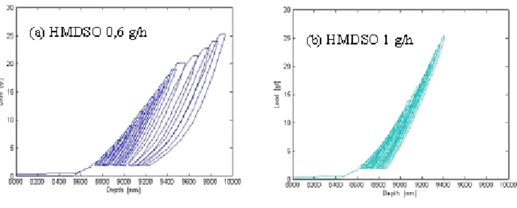
Figure 6 shows the load-unload curves obtained by cyclic nanoindentation for load 25 g (Figure 6). These runs of load-unload curves record the behavior of mechanical properties of interface of system substrate-coating a-SiC: H. The difference between layer (a) HMDSO: 0.6 g/h and (b) HMDSO: 1 g/h is evident.
Figure 6
Records of cyclic nanoindentation test for maximal load 25 g
Layer (a) has a higher condensation of curves, due to the hardness of the surface of the thin film in the first third of the share. However, other curves are more diluted (the penetration is more rapid), which detects a break-through of the layer on the interface of the system. The running of all cyclic curves of layer (b) is similar. In Figure 7 is shown the running of the universal hardness, depending on load. During the displacement interval from 0.1 µm to 1.38 µm, the hardness for system (a) is from 38 GPa to 7 GPa, and for system (b) it is from 30 GPa to 14 GPA. The running of hardness of both curves is similar; however, the values of hardness of the layer (b) are significantly higher.
Figure 7
Record of hardness as a function of displacement. Max. load 25 g
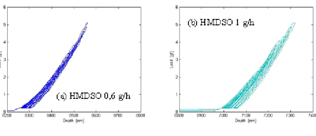
Figure 8 records the running of the change of hardness of the a-SiC: H film itself at the maximum load of 5 g. The running of the curves of both layers is similar, because the effect of substrate is minimal, due to the little load (Figure 8).
Figure 8
Record of cyclic nanoindentation test for maximal load 5 g
Figure 9
Record of hardness as a function of displacement. Max. load 5 g
From Figure 9 we can determine that in the displacement interval of 40 nm to 320 nm, the hardness for system (a) HMDSO: 0.6 g/h. is from 60 GPa to 20 GPa, and for system (b) HMDSO: 1 g/h., it is from 78 GPa to 20 GPA (Figure 9).
Conclusion
We achieved a-SiC:H coating on steel polished substrates under various flow of hexamethyldisiloxane. After 120 minutes, black, adherent, wear resistant and smooth coatings were obtained. The roughness of the layers was the same as for the substrates; Ra = 0.02. The thickness of the layer is 2 µm for system (a) and 4.2 µm for system (b). Via cyclic nanoindentation with a Vickers indenter, it was determined that the layer with flow of HMDSO - 1 g/h (system a) has higher value of hardness than the sample HMDSO – 0.6 (system b) for all loads of cyclic nanoindentation. The hardness of a single thin film is 20 GPa.
Acknowledgement
This research received support under Grant No. MSM 6840770012 of the Czech Republic Ministry of Education project “Trandisciplinary research in Biomedical Engineering II”. Authors gratefully acknowledge this support.
References
[1] A. Soum-Glaude, G.Rambaud, SE.Grillo, and L. Thomas: Investigation of the Tribological Behavior and its Relationship to the Microstructure and Mechanical Properties of a-SiC:H Films Elaborated by Low Frequency Plasma Assisted Chemical Vapor Deposition, Thin Solid Films 519 (2010) pp. 1266-1271
[2] M. Joinet, O. Borrod, L. Thomas, C. Picard, V. Lucas and F. Teyssandier.:
Effect of Plasma Treatments on the Adhesion Properties of PACVD a-
SiC:H Coatings on TA6V Alloy, Diamond & Related Materials 16 (2007) pp. 1254-1258
[3] I. Stepanek, O. Bláhová O, M. Kolega: Tenke vrstvy – vytvareni, vlastnosti, Plzen, 1994
[4] D. Tischler, Z. Budinská, I. Stepanek: Si and Gradient Layer Formed by RF PACVD Technology, Manufacturing Engineering 10 (2011) pp. 32-35 [5] Shan, and S. K. Sitaraman. Elastic-Plastic Characterization of Thin Films
Using Nanoindentation Technique. Thin Solid Films 437 (2003) pp. 176- 181
[6] B. Bhushan, Springer Handbook of Nanotechnology, Springer, 2004, p.677 [7] M. A. Ekwinska, Z. Rymuza, New Approach to Estimate Nanowear Test
Results through Nanoindentation Test. Microelectronic Engineering 87 (2010) pp. 1404-1409
[8] W. Jiang, J. Su, X. Feng. Effect of Surface Roughness on Nanoindenation Test of Thin Films. Engineering Fracture Mechanics 75 (2008) pp. 4965- 4972
[9] D. Lusk, M. Gore, W. Boardman. Thick DLC Films Deposited by PECVD on the Internal Surface of Cylindrical Substrates. Diamond and Related Materials 17 (2008) pp. 1613-1621