Overview and Complexity Evaluation of FBMC Transmitter Architectures
Husam Al-amaireh and Zsolt Kollár are with Department of Broadband Infocommunications and Electromagnetic Theory, Budapest University of Technology and Economics, Budapest, Hungary
{al-amaireh, kollar}@hvt.bme.hu
INFOCOMMUNICATIONS JOURNAL
Overview and Complexity Evaluation of FBMC Transmitter Architectures
Husam Al-amaireh and Zsolt Kollár
1
Overview and Complexity Evaluation of FBMC Transmitter Architectures
Husam Al-amaireh, Zsolt Koll´ar
Budapest University of Technology and Economics
Department of Broadband Infocommunications and Electromagnetic Theory Budapest, Hungary
{al-amaireh,kollar}@hvt.bme.hu
Abstract—Computational complexity is one of the key factors considered for evaluating transmitter performance of future 5G applications. In this contribution we have chosen Filter Bank MultiCarrier (FBMC) as it is the most possible candidate to replace/coexist with the Orthogonal Frequency Division Multi- plexing (OFDM) modulation. In the literature two main design approaches can be found for FBMC: Frequency Spreading (FS) and PolyPhase Network (PPN). From these two structures nu- merous schemes were derived. These schemes are studied and the complexity (real multiplications and additions) for each scheme is compared. Based on the complexity calculations, the simulation results show that PPN has a better complexity performance compared with FS. Also, the alternative PPN schemes have significant improvement in complexity compared to the standard PPN.
Index Terms—FBMC, complexity, polyphase, frequency spreading .
I. INTRODUCTION
Orthogonal Frequency Division Multiplexing (OFDM) is considered as one of the most prevailing technologies that dominate the broadband wireless digital communication so far. The fundamental principle of OFDM is based on dividing the spectrum into orthogonal sub-bands in an efficient manner while keeping the transmitter and receiver design simple.
Despite several advantages, OFDM suffers from many short- comings that render it unsatisfactory for the 5th Generation (5G) requirements. Also it is expected that 5G will heavily implement Machine-Type Communications (MTC) which is further classified (according to FP7 project METIS) into two classes; massive (mMTC) and ultra-reliable (uMTC). While the first class suggests that tens of billions of low complexity machine-type devices will be implemented, the second puts emphasis on the availability, latency and reliability [1]. In order to satisfy the future requirements, several contenders for the physical layer modulation are competing to prove the best promising performance for the next generation of communica- tion interfaces. These candidates are Filter Bank MultiCarrier (FBMC), Universal Filtered MultiCarrier (UFMC), General- ized Frequency Division Multiplexing (GFDM) and OFDM [2]. The process for deciding which is the best candidate is non trivial, many key features have to be considered and each feature has to be taken into account with different weighting factors which help in the overall evaluation and decision. Some of these features are peak-to-average power ratio, power spec-
tral density, spectral efficiency, multiple access interference and also the design complexity of the transceiver chain.
In this paper the FBMC modulation is investigated, as it is considered the most favored candidate for 5G physical layer.
This technique is also known as Offset Quadrature Amplitude (OQAM) OFDM or Staggered MultiTone (SMT) modulation.
This paper focuses mainly on the computational complexity of the various FBMC transmitter implementations. In general, the structure of the transmitter is composed of several blocks where each block performs certain signal processing tasks with different complexity; for example the encoder block which encodes input information bits, the encoded bits are divided into groups of size log2Si and mapped into symbols from SiQAM, whereSi is the number of QAM constellations, and then the data are modulated by the multicarrier modulator.
For the purpose of the comparisons among different imple- mentations, the common parts are not included in complexity calculations where only the multicarrier part is considered, it is also assumed that all input subcarriers are utilized, i.e no guard bands are used at the sides. The complexity requirement of OFDM is also included in the comparison as a reference so that the additional requirements of the FBMC implementations can be better evaluated. Furthermore, the computations are performed in terms of the required real valued multiplications and additions.
Two different design structures for FBMC transmitters can be found in the literature, the first one is the FS which is based on applying the sub band filtering in frequency domain with increased size of Inverse Fast Fourier Transform (IFFT) as shown in [3], and the second type is where PPN is applied in conjunction with an IFFT of a regular symbols size [4].
Several design structures were proposed to reduce complexity, in [5] and [6], a complexity reduction of almost half size is achieved with the aid of some additional signal processing steps. Another alternative structure was introduced in [7]
where similarly, a complexity reduction of almost half size can be achieved by the modifications to the butterflies structure of the applied IFFT.
The paper is organized as follows. Section II presents the baseband FBMC signal model. In Section III the investigated FBMC transmitter schemes [3]–[7] are briefly presented and their complexity requirements are derived. Section IV presents results of the complexity comparison between the introduced transmitter schemes. Finally, Section V draws the conclusion.
1
Overview and Complexity Evaluation of FBMC Transmitter Architectures
Husam Al-amaireh, Zsolt Koll´ar
Budapest University of Technology and Economics
Department of Broadband Infocommunications and Electromagnetic Theory Budapest, Hungary
{al-amaireh,kollar}@hvt.bme.hu
Abstract—Computational complexity is one of the key factors considered for evaluating transmitter performance of future 5G applications. In this contribution we have chosen Filter Bank MultiCarrier (FBMC) as it is the most possible candidate to replace/coexist with the Orthogonal Frequency Division Multi- plexing (OFDM) modulation. In the literature two main design approaches can be found for FBMC: Frequency Spreading (FS) and PolyPhase Network (PPN). From these two structures nu- merous schemes were derived. These schemes are studied and the complexity (real multiplications and additions) for each scheme is compared. Based on the complexity calculations, the simulation results show that PPN has a better complexity performance compared with FS. Also, the alternative PPN schemes have significant improvement in complexity compared to the standard PPN.
Index Terms—FBMC, complexity, polyphase, frequency spreading .
I. INTRODUCTION
Orthogonal Frequency Division Multiplexing (OFDM) is considered as one of the most prevailing technologies that dominate the broadband wireless digital communication so far. The fundamental principle of OFDM is based on dividing the spectrum into orthogonal sub-bands in an efficient manner while keeping the transmitter and receiver design simple.
Despite several advantages, OFDM suffers from many short- comings that render it unsatisfactory for the 5th Generation (5G) requirements. Also it is expected that 5G will heavily implement Machine-Type Communications (MTC) which is further classified (according to FP7 project METIS) into two classes; massive (mMTC) and ultra-reliable (uMTC). While the first class suggests that tens of billions of low complexity machine-type devices will be implemented, the second puts emphasis on the availability, latency and reliability [1]. In order to satisfy the future requirements, several contenders for the physical layer modulation are competing to prove the best promising performance for the next generation of communica- tion interfaces. These candidates are Filter Bank MultiCarrier (FBMC), Universal Filtered MultiCarrier (UFMC), General- ized Frequency Division Multiplexing (GFDM) and OFDM [2]. The process for deciding which is the best candidate is non trivial, many key features have to be considered and each feature has to be taken into account with different weighting factors which help in the overall evaluation and decision. Some of these features are peak-to-average power ratio, power spec-
tral density, spectral efficiency, multiple access interference and also the design complexity of the transceiver chain.
In this paper the FBMC modulation is investigated, as it is considered the most favored candidate for 5G physical layer.
This technique is also known as Offset Quadrature Amplitude (OQAM) OFDM or Staggered MultiTone (SMT) modulation.
This paper focuses mainly on the computational complexity of the various FBMC transmitter implementations. In general, the structure of the transmitter is composed of several blocks where each block performs certain signal processing tasks with different complexity; for example the encoder block which encodes input information bits, the encoded bits are divided into groups of size log2Si and mapped into symbols from SiQAM, whereSiis the number of QAM constellations, and then the data are modulated by the multicarrier modulator.
For the purpose of the comparisons among different imple- mentations, the common parts are not included in complexity calculations where only the multicarrier part is considered, it is also assumed that all input subcarriers are utilized, i.e no guard bands are used at the sides. The complexity requirement of OFDM is also included in the comparison as a reference so that the additional requirements of the FBMC implementations can be better evaluated. Furthermore, the computations are performed in terms of the required real valued multiplications and additions.
Two different design structures for FBMC transmitters can be found in the literature, the first one is the FS which is based on applying the sub band filtering in frequency domain with increased size of Inverse Fast Fourier Transform (IFFT) as shown in [3], and the second type is where PPN is applied in conjunction with an IFFT of a regular symbols size [4].
Several design structures were proposed to reduce complexity, in [5] and [6], a complexity reduction of almost half size is achieved with the aid of some additional signal processing steps. Another alternative structure was introduced in [7]
where similarly, a complexity reduction of almost half size can be achieved by the modifications to the butterflies structure of the applied IFFT.
The paper is organized as follows. Section II presents the baseband FBMC signal model. In Section III the investigated FBMC transmitter schemes [3]–[7] are briefly presented and their complexity requirements are derived. Section IV presents results of the complexity comparison between the introduced transmitter schemes. Finally, Section V draws the conclusion.
Transmitter Architectures
Husam Al-amaireh, Zsolt Koll´ar
Budapest University of Technology and Economics
Department of Broadband Infocommunications and Electromagnetic Theory Budapest, Hungary
{al-amaireh,kollar}@hvt.bme.hu
Abstract—Computational complexity is one of the key factors considered for evaluating transmitter performance of future 5G applications. In this contribution we have chosen Filter Bank MultiCarrier (FBMC) as it is the most possible candidate to replace/coexist with the Orthogonal Frequency Division Multi- plexing (OFDM) modulation. In the literature two main design approaches can be found for FBMC: Frequency Spreading (FS) and PolyPhase Network (PPN). From these two structures nu- merous schemes were derived. These schemes are studied and the complexity (real multiplications and additions) for each scheme is compared. Based on the complexity calculations, the simulation results show that PPN has a better complexity performance compared with FS. Also, the alternative PPN schemes have significant improvement in complexity compared to the standard PPN.
Index Terms—FBMC, complexity, polyphase, frequency spreading .
I. INTRODUCTION
Orthogonal Frequency Division Multiplexing (OFDM) is considered as one of the most prevailing technologies that dominate the broadband wireless digital communication so far. The fundamental principle of OFDM is based on dividing the spectrum into orthogonal sub-bands in an efficient manner while keeping the transmitter and receiver design simple.
Despite several advantages, OFDM suffers from many short- comings that render it unsatisfactory for the 5th Generation (5G) requirements. Also it is expected that 5G will heavily implement Machine-Type Communications (MTC) which is further classified (according to FP7 project METIS) into two classes; massive (mMTC) and ultra-reliable (uMTC). While the first class suggests that tens of billions of low complexity machine-type devices will be implemented, the second puts emphasis on the availability, latency and reliability [1]. In order to satisfy the future requirements, several contenders for the physical layer modulation are competing to prove the best promising performance for the next generation of communica- tion interfaces. These candidates are Filter Bank MultiCarrier (FBMC), Universal Filtered MultiCarrier (UFMC), General- ized Frequency Division Multiplexing (GFDM) and OFDM [2]. The process for deciding which is the best candidate is non trivial, many key features have to be considered and each feature has to be taken into account with different weighting factors which help in the overall evaluation and decision. Some of these features are peak-to-average power ratio, power spec-
tral density, spectral efficiency, multiple access interference and also the design complexity of the transceiver chain.
In this paper the FBMC modulation is investigated, as it is considered the most favored candidate for 5G physical layer.
This technique is also known as Offset Quadrature Amplitude (OQAM) OFDM or Staggered MultiTone (SMT) modulation.
This paper focuses mainly on the computational complexity of the various FBMC transmitter implementations. In general, the structure of the transmitter is composed of several blocks where each block performs certain signal processing tasks with different complexity; for example the encoder block which encodes input information bits, the encoded bits are divided into groups of size log2Si and mapped into symbols from SiQAM, whereSiis the number of QAM constellations, and then the data are modulated by the multicarrier modulator.
For the purpose of the comparisons among different imple- mentations, the common parts are not included in complexity calculations where only the multicarrier part is considered, it is also assumed that all input subcarriers are utilized, i.e no guard bands are used at the sides. The complexity requirement of OFDM is also included in the comparison as a reference so that the additional requirements of the FBMC implementations can be better evaluated. Furthermore, the computations are performed in terms of the required real valued multiplications and additions.
Two different design structures for FBMC transmitters can be found in the literature, the first one is the FS which is based on applying the sub band filtering in frequency domain with increased size of Inverse Fast Fourier Transform (IFFT) as shown in [3], and the second type is where PPN is applied in conjunction with an IFFT of a regular symbols size [4].
Several design structures were proposed to reduce complexity, in [5] and [6], a complexity reduction of almost half size is achieved with the aid of some additional signal processing steps. Another alternative structure was introduced in [7]
where similarly, a complexity reduction of almost half size can be achieved by the modifications to the butterflies structure of the applied IFFT.
The paper is organized as follows. Section II presents the baseband FBMC signal model. In Section III the investigated FBMC transmitter schemes [3]–[7] are briefly presented and their complexity requirements are derived. Section IV presents results of the complexity comparison between the introduced transmitter schemes. Finally, Section V draws the conclusion.
.
.
.
.
.
. S
0 [m]
S 0 [m]
S 1 [m]
S 1 [m]
S N−1 [m]
S N−1 [m]
ej2πNn
ej2πN(N−1)n j0
j1
j1
j2
j(N−1)
jN
...
... ...
p0[n]
p0[n−N/2]
p0[n]
p0[n−N/2]
p0[n]
p0[n−N/2]
. . .
.
.
x[n]
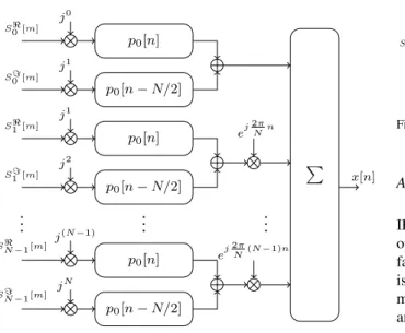
Fig. 1. FBMC signal model using direct implementation
II. FBMCSIGNAL MODEL
In this section we briefly introduce the baseband signal model for the FBMC modulation.
First, the binary data is modulated using QAM. The com- plex symbols generated by the QAM mapper are divided into consecutive symbols with length of N. The mth symbol is split into a real parts[m]and an imaginary parts[m]. The real and imaginary parts are multiplied by the phase rotation factorjk and jk+1, respectively, wherek corresponds to the kthsubcarrier. Then, the two signals are filtered by a prototype filterp0 with a length of L=KN – whereK is an integer number – and summed. The real and imaginary parts of the QAM symbols are transmitted with anN/2delay. The filtered real and imaginary signals are summed and modulated with the correspondingkthcomplex subcarrier with the frequency of ej2πNk. Finally, the N paralell streams are added to form the discrete basedband FBMC signalx[n], which can be also mathematically expressed as
x[n] =
∞
m=−∞
N−1
k=0
jksk[m]p0[n−mN] +
jk+1sk[m]p0
n−mN−N 2
ej2πNkn, (1) wherej=√
−1. The corresponding FBMC transmitter model is shown in Fig. 1.
III. COMPLEXITY ANALYIS OFFBMCTRANSMITTER SCHEMES
In this section the complexity requirements are detailed for various FBMC transmitter structures, also for the purpose of complexity calculations we have classified the structures into two main categories: standard structures, and improved PPN structures. Furthermore, as all of the discussed FBMC implementations include the IFFT, a brief description for its complexity is given prior to the discussion.
S[m]
{·}
{·}
jk
jk+1
Spreading Filtering
Spreading Filtering
NK-IFFT
NK-IFFT P/S Overlap/Sum
P/S Overlap/Sum
N/2 offset
.x[n]
x[n]
x[n]
Fig. 2. FS implementation
A. IFFT complexity
During the calculations, split-radix implementation of the IFFT is considered as it significantly improves the number of operations compared to other solutions [8]. Another important factor which plays a major rule in complexity calculations is the multiplication of two complex numbers. A complex multiplication can be achieved through 3 real multiplications and 3 real additions or 4 real multiplications and 2 real additions. As multiplication is more costly than additions in hardware implementations the 3 real additions and 3 real multiplications will be considered thourghout this paper. As a result the complexity requirement for the IFFT of an input sizeN can be given as:
MIFFT=N(log2N−3) + 4, (2) AIFFT= 3N(log2N−1) + 4, (3) where M,A are the number of real multiplications and additions, respectively.
B. Standard Structures
First, the straightforward implementations of the FBMC signal model are discussed which are commonly presented in the literature.
1) Direct implementation: The complexity of the direct implementation – presented in Fig. 1 – is based on two parallel filtering operations (requiring2N K real multiplications and 2(N K−1)real additions per subcarrier), the modulation with complex subcarrier frequencies (requiring 3 real multiplica- tions and 3 real additions per subcarrier) and finally summing theN complex streams (requiringN−1real additions). The multiplication with the phase rotation factor and the addition of the two filter outputs are considered negligible. As a result, the required complexity calculations for the direct implementation can be expressed in the function ofN andK as
Mdirect= 2N2K+3N, (4)
Adirect= 2N(N K−1)+3N+N−1. (5) 2) Frequency spreading: The block diagram of the FBMC transmitter based on FS [3] can be seen in Fig. 2. As a first step, the real and imaginary symbols are extracted and the phase rotation factor is applied. Then, each signal is multiplied by2K−1frequency domain coefficientsPkof the prototype filterp0, were the multiplication with coefficientPk=0=1can be excluded. As a result, the total number of operations before applyingN K-IFFT stage is the following:
Mspreading=N(2K−2), (6)
S[m]
{·}
{·}
jk
jk+1
N-IFFT
N-IFFT
Polyphase filtering
Polyphase
filtering offsetN/2 .x[n]
x[n]
x[n]
Fig. 3. Polyphase implementation with Standard PPN using 2 IFFTs
As neighboring subchannels are either purely real or purely imagainary, no additions are required.
As the FBMC symbols are constructed in the frequency domain, an IFFT with size N K is required. As a result the calculations requirements can be calculated according to Eq. (2) and Eq. (3) for anN K-IFFT.
As a last step, the overlappig of the time domain FBMC symbols require only N K complex additions resulting in a complexity requirement of
Aoverlap= 2N K. (7)
Finally, the resulting calculation complexity of the FS implementation for the two branches – considering the final adder, which can be realized by 2 real valued additions – can be expressed as:
MFS = 2 (2N(K−1)+(N K(log2N K−3)+4)), (8) AFS = 2 ((3N K(log2N K−1)+4) +2N K) +2. (9) 3) Standard PPN implementation: Another approach is presented in [4] where the frequency domain filtering is moved from the frequency domain to time domain using PPN decomposition of the prototype filter. This way the FBMC signal generation can be achieved by anN-IFFT and a PPN.
The block diagram of the proposed FBMC transmitter can be seen in Fig. 3.
As mentioned in the previous section the multiplication with the phase rotation factor is negligible. The size of the IFFT will be equal toN, the cost of applying IFFT on purely real or purely imaginary inputs will be the same as complex input signals [9], so the number of multiplications and additions can be expressed as in Eq. (2) and Eq. (3), respectively.
Furthermore, due to the PPN implementation theN samples of the time domain signal will be filtered by K coefficients where the cost of filtering operations can be expressed as
Mfilt= 2N K, (10)
Afilt= 2N(K−1). (11) As a result, the total complexity requirement for the real and imaginary paths – and taking the final adder into consideration – can be derived as
MPPN= 2(N(log2N−3)+4+2N K), (12) APPN= 2(3N(log2N−1)+4+2N(K−1))+2. (13) C. Improved PPN Structures
In this section methods for improving the computational complexity of the Standard PPN structure are discussed.
S[m] N-IFFT Signal
separation
N 4 circular
shift
Polyphase filtering
Polyphase filtering offsetN/2
.x[n]
x[n]
x[n]
Fig. 4. Polyphase implementation with Reduced PPN I using 1 IFFT
S[m]
{·}
{·}
jk
jk+1 Pruned N-IFFT
Pruned N-IFFT
Append Sodd∗[m]
Append Sodd∗[m]
Polypase filtering
Polypase
filtering offsetN/2 .x[n]
x[n]
x[n]
Fig. 5. Polyphase implementation with Reduced PPN II using 2 pruned IFFTs
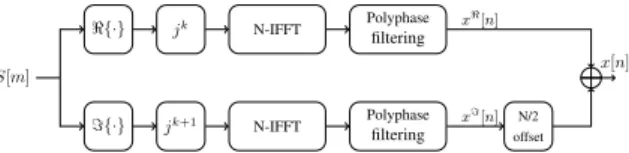
1) Reduced PPN I.: The implementation cost of the stan- dard PPN solution can be further reduced. In [5], the two purely real input symbols are combined together as single complex input symbols which reduces the number of required IFFTs by half and some additional signal processing. For signals separation after the IFFT, as shown in [6], [10], there are no extra multiplications needed except a multiplication with 1/2 which can be achieved by simple binary bit shift. On the other hand, extra additions are required for the separation of the real and imaginary signal parts:
Asepration= 4N. (14)
As a result the complexity requirement for the reduced PPN solution – with the final adder – can be calculated as:
Mreduced,I=N(log2N−3)+4+4N K, (15) Areduced,I= 3N(log2N−1)+4+4N(K−1)+4N+2. (16) 2) Reduced PPN II.: Another solution for complexity re- duction of standard PPN implementation was proposed in [7]. The solution takes advantage of the complex conjugate symmetry between odd and even indices of the IFFT. Con- cerning the computational complexity, it has reduced the cost by only calculating the even indices and design a pruned IFFT structure which cancels the unneeded calculations of the IFFT butterflies, then the samples of the odd indices will be calculated from the results of the even indices. The design structure shown in Fig. 5 is similar to standard PPN solution with a difference of implementing a pruned IFFT instead of using a standard IFFT. As a result the total complexity requirement can be expressed using Eq. (12) and Eq. (13) by substituting the calculation requirements of an IFFT with the requirements of a pruned IFFT as
Mreduced,II= 2
N
2
log2N 2−3
+4+2N K
, (17) Areduced,II= 2
3N
2
log2N 2−1
+4+2N(K−1)
+2.
(18) 3) Reduced PPN III.: The third introduced solution for reducing complexity can be considered as a hybrid solution,
S[m]
{·}
{·}
N 2to N expansion
N 2to N expansion
N 4circular
shift
N 4circular
shift N
2IFFT
N 2IFFT
Polyphase filtering
Polyphase
filtering offsetN/2 .x[n]
x[n]
x[n]
Fig. 6. Polyphase implementation with Reduced PPN III using two half size IFFTs
which means that it combines some properties of both Stan- dard PPN and Reduced PPN I at the same time. In [6] the solution suggests that each of the two real input streams (real part and imaginary part) is processed separately (just as standard solution), however, each sybmol of size N of each stream is split into twoN/2size symbols, the two halves are combined as oneN/2 complex symbol and an IFFT of size N/2will be applied, then at the output of IFFT - after some signal processing - each symbol will be spread again intoN size as shown in Fig. 6. The total complexity can be considered as a standard PPN withN/2-IFFT in additon to some signal processing to spread the symbols. The complexity for signal separation as in [6], [10], can be calculated as the following,
Mseparation= 2(2N+1), (19)
Aseparation= 2(7N−1), (20) So the total complexity of Reduced PPN III becomes:
Mreduced,III= 2
N
2
log2N 2−3
+5+2N K+2N
, (21) Areduced,III= 2
3 N
2
log2N 2 −1
+ 3 + +2N(K−1) + 7N
+ 2. (22)
IV. COMPARISON OF THEFBMCTRANSMITTER STRUCTURES
In the previous section, a brief descriptions of the var- ious FBMC transmitter structures and their complexity in terms of additions and multiplications were derived. In this section these methods are compared in terms of complexity requirements and further their advantages and implementation aspects, the complexity requirement of OFDM – using a single N-IFFT – is added to all figures as a reference in order to show the added complexity requirements of the different FBMC transmitter structures. A summary of the complexity requirement can be seen in Table I in function of N and K. For comparison, the presented equation are evaluated for K= 4, which is a commonly used value in practical FBMC implementations.
1) Complexity requirements for standard structures: The required number of real additions and multiplications for different methods of the standard FBMC transmitter can be observed in Fig. 7 and Fig. 8 respectively, as functions of the number of subcarriers N. It can be seen that the direct im- plementation is extremely inefficient. The FS implementation can significantly reduce the complexity requirements. Further reduction can be achieved using the Standard PPN solutions.
Fig. 7. Number of additions for the standard FBMC transmitters as a function of the number of subcarriersN
Fig. 8. Number of multiplications for the standard FBMC transmitters as a function of the number of subcarriersN
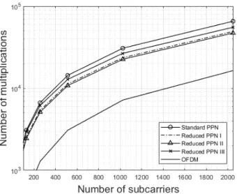
2) Complexity requirements for improved PPN structures:
Fig. 9 and Fig. 10 show the required number of real additions and multiplications respectively for improved PPN methods of FBMC transmitter as function of the number of subcarriers N. Based on the results shown in the figures it can be stated that the three introduced methods for reducing complexity have a relatively similar complexity. The Reduced PPN II has the lowest complexity requirements. The Reduced PPN I performs slightly worse. The Reduced PPN III has the worst performance among the presented methods. It can also be stated that the complexity requirement for all Reduced PPN methods is almost half of the Standard PPN implementation, however the complexity requirement of OFDM is significantly lower compared with all FBMC structures.
TABLE I
COMPARISON OF THE NUMBER OF OPERATIONS FOR THE VARIOUSFBMCTRANSMITTERS SCHEMES
Method Number of Multiplication Number of Additions
Direct Implementation 2N2K+ 3N 2N(N K−1) + 3N+N−1
FS 2 (2N(K−1) + (N K(log2N K−3) + 4)) 2 ((3N K(log2N K−1)+4) +2N K) + 2 Standard PPN 2(N(log2N−3) + 4 + 2N K) 2(3N(log2N−1) + 4 + 2N(K−1)) + 2 Reduced PPN I N(log2N−3) + 4 + 4N K 3N(log2N−1)+4+4N(K−1)+4N+2 Reduced PPN II 2(N/2(log2N/2−3) + 4 + 2N K) 2(3N/2(log2N/2−1)+4+2N(K−1))+2 Reduced PPN III 2(N/2(log2N/2−3) + 5 + 2N+ 2N K) 2(3N/2(log2N/2−1) + 3 + 7N+ 2N(K−1)) + 2
Fig. 9. Number of additions for the improved FBMC transmitters as a function of the number of subcarriersN
Fig. 10. Number of multiplications for the improved FBMC transmitters as a function of the number of subcarriersN
3) Design aspects: In this section a brief discussion of the further advantages of each FBMC design structure is pre- sented. The direct implementation is extremely inefficient to be implemented, it can be viewed as the ”ancestor” which led to the derivation of other structures. When comparing FS and PPN, although the PPN structure has a smaller complexity, for the receiver implementation subchannel equalization is carried out in time domain which introduces additional memory and delay [3], on the other hand the channel equalization in FS structure is much simpler.
When comparing the three improved PPN methods, Re- duced PPN II provides best performance in terms of com- plexity. On the other hand, the Reduced PPN I – as it uses a single IFFT – can be a flexible solution if an existing OFDM transmitter has to be extended/reconfigured for FMBC trans- mission [5]. Furthermore, the Reduced PPN III is beneficial in hardware implementations with reduced arithmetic precision, due to the fact that it has the lowest quantization error, as shown in [6].
V. CONCLUSION
FBMC is considered as one of the most favored candidates for future 5G physical layer modulation. There are different design approaches for FBMC where each structure has differ- ent complexity requirements. In this paper a brief description for standard and suggested improved FBMC structures was given. The complexity requirement for each modulator archi- tecture was derived. Beside design structure, the complexity is affected by the FFT algorithm and calculations of complex numbers multiplications. The complexity requirements were calculated in terms of number of real addition and multi- plications. The simulation results show that PPN is more efficient than FS. The improved PPN structures can achieve a complexity reudction of almost half compared to the Standard PPN.
ACKNOWLEDGMENT
This work was supported by the J´anos Bolyai Research Fellowship of the Hungarian Academy of Sciences, by the BME Artificial Intelligence FIKP grant of EMMI (BME FIKP- MI/ SC) and the DAAD research grant for doctoral candidates and young academics and scientists.
REFERENCES
[1] C. Bockelmann, N. Pratas, H. Nikopour, K. Au, T. Svensson, C. Ste- fanovic, P. Popovski, and A. Dekorsy, “Massive machine-type communi- cations in 5G: Physical and mac-layer solutions,”IEEE Communications Magazine, vol. 54, no. 9, pp. 59–65, 2016.
[2] R. Gerzaguet, N. Bartzoudis, L. G. Baltar, V. Berg, J.-B. Dor´e, D. Kt´enas, O. Font-Bach, X. Mestre, M. Payar´o, M. F¨arber, and K. Roth, “The 5G candidate waveform race: a comparison of complexity and performance,”EURASIP Journal on Wireless Communications and Networking, vol. 2017, no. 1, p. 13, Jan 2017. [Online]. Available:
https://doi.org/10.1186/s13638-016-0792-0
[3] D. Mattera, M. Tanda, and M. Bellanger, “Frequency-spreading imple- mentation of OFDM/OQAM systems,” in2012 International Symposium on Wireless Communication Systems (ISWCS), Aug 2012, pp. 176–180.
[4] P. Siohan, C. Siclet, and N. Lacaille, “Analysis and design of OFDM/O- QAM systems based on filterbank theory,”IEEE Transactions on Signal Processing, vol. 50, no. 5, pp. 1170–1183, May 2002.
[5] L. Varga and Zs. Koll´ar, “Low complexity FBMC transceiver for FPGA implementation,” inRadioelektronika, 2013 23rd International Conference, Apr. 2013, pp. 219–223.
[6] Zs. Koll´ar and H. Al-amaireh, “FBMC transmitters with reduced com- plexity,”Radioengineering, vol. 27, no. 4, pp. 1147–1154, Dec. 2018.
[7] Y. Dandach and P. Siohan, “FBMC/OQAM modulators with half complexity,” in2011 IEEE Global Telecommunications Conference - GLOBECOM 2011, Dec 2011, pp. 1–5.
[8] P. Duhamel and H. Hollmann, “‘split radix’ FFT algorithm,”Electronics letters, vol. 20, no. 1, pp. 14–16, 1984.
[9] H. V. Sorensen, D. Jones, M. Heideman, and C. Burrus, “Real-valued fast fourier transform algorithms,” IEEE Transactions on acoustics, speech, and signal processing, vol. 35, no. 6, pp. 849–863, 1987.
[10] E. O. Brigham,The Fast Fourier Transform. Prentice-Hall Inc., 1974.
Husam AL-AMAIREH was born in 1973. He received his M.Sc. degree in computer science from Yarmouk University in Jordan in 2004. He is pursu- ing a Ph.D. degree at the Department of Broadband Infocommunication and Electromagnetic Theory at the Budapest University of Technology and Eco- nomics. He is currently a member of the MATLAB Laboratory. His research interests are digital signal processing and wireless communications.
Zsolt KOLL ´AR was born in 1983. He received his Ph.D. degree in electric engineering from the Budapest University of Technology and Economics in 2013. He is currently an assistant professor at the Department of Broadband Infocommunication and Electromagnetic Theory. Since 2016, he is the head of the MATLAB Laboratory. His research interests include digital signal processing, quantization effects and wireless communication.
Husam AL-AMAIREH was born in 1973. He received his M.Sc. degree in computer science from Yarmouk University in Jordan in 2004. He is pursu- ing a Ph.D. degree at the Department of Broadband Infocommunication and Electromagnetic Theory at the Budapest University of Technology and Eco- nomics. He is currently a member of the MATLAB Laboratory. His research interests are digital signal processing and wireless communications.
Zsolt KOLLÁ́R was born in 1983. He received his Ph.D. degree in electric engineering from the Bu- dapest University of Technology and Economics in 2013. He is currently an assistant professor at the Department of Broadband Infocommunication and Electromagnetic Theory. Since 2016, he is the head of the MATLAB Laboratory. His research interests include digital signal processing, quantization ef- fects and wireless communication.