(will be inserted by the editor)
Scalable Modeling Technologies in the Wild
An Experience Report on Wind Turbines Control Applications Development
Abel Gómez · Xabier Mendialdua · Konstantinos Barmpis · Gábor Bergmann · Jordi Cabot · Xabier de Carlos · Csaba Debreceni · Antonio Garmendia · Dimitrios S. Kolovos · Juan de Lara
Received: date / Accepted: date
Abstract Scalability in modeling has many facets, includ- ing the ability to build larger models and domain specific languages (DSLs) efficiently. With the aim of tackling some of the most prominent scalability challenges in Model-Based Engineering (MBE), the MONDO EU project developed the theoretical foundations and open-source implementation of a platform for scalable modeling and model management.
The platform includes facilities for building large graphical DSLs, for splitting large models into sets of smaller inter- related fragments, to index large collections of models to speed-up their querying, and to enable the collaborative con- struction and refinement of complex models, among other features.
This paper reports on the tools provided by MONDO that Ikerlan, a medium-sized technology center which in the last decade has embraced the MBE paradigm, adopted in order to A. Gómez
Internet Interdisciplinary Intitute (IN3), Universitat Oberta de Catalunya (UOC), Barcelona, Spain
E-mail: agomezlla@uoc.edu X. Mendialdua·X. de Carlos
Ikerlan Research Center, Arrasate, Spain E-mail: {xmendialdua | xdecarlos}@ikerlan.es Konstantinos Barmpis·D. S. Kolovos
Dept. of Computer Science, University of York, York, UK E-mail: {dimitris.kolovos | konstantinos.barmpis}@york.ac.uk G. Bergmann·C. Debreceni
MTA-BME Lendület Research Group on Cyber-Physical Systems, Bu- dapest University of Technology and Economics, Budapest, Hungary E-mail: {bergman | debreceni}@mit.bme.hu
J. Cabot
ICREA – Internet Interdisciplinary Intitute (IN3), Universitat Oberta de Catalunya (UOC), Barcelona, Spain
E-mail: jordi.cabot@icrea.cat A. Garmendia·J. de Lara
Universidad Autónoma de Madrid, Madrid, Spain E-mail: {Antonio.Garmendia | Juan.deLara}@uam.es
improve their processes. This experience produced as a result a set of model editors and related technologies that fostered collaboration and scalability in the development of wind tur- bine control applications. In order to evaluate the benefits obtained, an on-site evaluation of the tools was performed.
This evaluation shows that scalable MBE technologies give new growth opportunities to small and medium-sized orga- nizations.
Keywords Model-Based Engineering (MBE), Scalabil- ity, Domain Specific Graphical Modeling Languages, Collaborative Modeling, Model Indexing, Experience Report
1 Introduction
Ikerlan is a Spanish private non-profit technology center cre- ated in 1974, and a technological R&D actor within the Mondragon Corporation [50]. Ikerlan is a point of reference for innovation, dedicated to advanced technology transfer to industry and comprehensive product development (from con- cept to implementation) for a wide variety of domains: en- ergy (wind and solar power, and storage systems), transporta- tion (railway and vertical), automation, industrial, health, home appliances, etc. Ikerlan works closely with companies to improve their competitiveness through the application of technological knowledge to develop innovative products as well as by providing new tools and methodologies for imple- mentation in design and production processes. It has a staff of more than 200 qualified researchers and engineers, with experience in interdisciplinary work and capable of tackling complex problems. As a center of excellence in the transfer of technology, more than 800 R&D projects have been com- pleted until 2019 in cooperation with companies developing new products, implementing customized systems in design,
and manufacturing processes. The actions of Ikerlan are de- voted to providing product, process and service innovation for companies. To achieve these ambitious goals, Ikerlan of- fers comprehensive solutions that combine the three domains in which it has a high degree of specialization and expertise:
Electronics, Information and Communication Technologies (EICT), Energy and Power Electronics and Advanced Man- ufacturing.
Focusing on energy, and specifically in wind power, Iker- lan has been working for the last 11 years in the develop- ment of supervisory and control platforms for wind turbines for one of the world’s leading companies in the field of re- newable energy. Wind turbines are complex systems where hardware and software components need to interact in in- tricate ways. To tackle this complexity, Model-based Engi- neering (MBE) [85] technologies were introduced in 2008 in Ikerlan for the engineering of the supervisory and con- trol systems. The goal for adopting and investing in MBE was to improve the productivity and competitiveness of its industrial customers by enhancing their software develop- ment processes using, as Section 2 sketches, Domain Spe- cific Languages (DSL) [53] and code generators [21]. The experiences reported by customers showed significant pro- ductivity increases, indicating that MBE has been critical in the development of new software products faster, cheaper and with fewer errors than in previous projects.
However, too often, MBE tools and methodologies have targeted the construction and processing of small models in non-distributed environments. This focus neglects common scalability challenges [59], considering that a more typi- cal scenario involves different engineers working in collab- oration at distributed locations. Handling these issues is a challenging task that requires specific solutions that foster scalability, as we discuss in Section 3.
In 2013, the MONDO project1 was launched with the aim of tackling some of the most prominent challenges of scalability in MBE by developing the theoretical foundations and open-source implementation of a platform for scalable modeling and model management. Achieving scalability in MBE involves Achieving scalability in modeling and MDE involves being able to construct large models and domain specific languages in a systematic manner, enabling teams of modelers to construct and refine large models in a col- laborative manner, advancing the state-of-the-art in model querying and transformations tools so that they can cope with large models (of the scale of millions of model elements), and providing an infrastructure for efficient storage, indexing and retrieval of large models. Among the technologies devel- oped2, Section 4 focuses on the ones that can provide Ikerlan the opportunity to offer its customers software development methodologies in geographically distributed scenarios where
1 http://www.mondo-project.org/
2 http://www.mondo-project.org/technologies
multiple users can work collaboratively with large mod- els and DSLs; and Section 5 describes the different solutions developed in Ikerlan using the MONDO platform.
Section 6 describes how the scalable MONDO technolo- gies have been evaluated in Ikerlan and presents the results obtained. Section 7 analyses related work, especially focus- ing on the technologies developed and adopted in this expe- rience. Finally, Section 8 draws conclusions and discusses this experience on the application of scalable modeling tech- nologies in a company like Ikerlan.
This article is an extension of our previous paper pre- sented at the ECMFA’17 conference [44]. In this version, we provide an extended description of the MONDO framework in Section 4, expanding upon the capabilities of the different solutions of the MONDO framework that are of interest for Ikerlan. We also provide further details on how the MONDO framework was adopted in Ikerlan, presenting in Section 5 a description of the different solutions implemented. In Sec- tion 6, we report on the evaluations performed, including a description of the different experimental setups. And finally, we provide a comparison with related work in Section 7.
2 Background: Towards an MBE Development Process In 2008 Ikerlan adopted the MBE paradigm to develop soft- ware applications in a wide range of domains to increase the productivity in their software development processes. In 2008, the application of this more modern MBE approach started in its wind turbines division [100]. This section in- troduces the changes such modernization implied and the improvements achieved.
The result of this initial modernization effort forms the baseline for the experience reported in this paper, and pro- vides the rationale for the decisions taken and technologies used for the evolution of the framework.
2.1 Wind Turbines
A wind turbine is a complex system composed of a set of physical subsystems whose aim is to convert wind energy into electrical energy. The Wind Turbine Control System (WTCS) [1] is the system which monitors and controls all of the subsystems that make up the wind turbine. Its aim is to maximize the generation of electrical energy, always ensuring the correct operation of the turbine and avoiding any problem which can cause any damage to it. It moni- tors the status of the wind turbine and the environmental conditions, making decisions to obtain the highest energy production. The WTCS is a HW/SW system that runs on a dedicated hardware platform. This is connected to the wind turbine through assorted communications to receive infor-
mation from inputs (sensors, device state signals, etc.) and to actuate on outputs (device actuators).
2.2 In the Beginning, there was only Code
Ikerlan’s work is primarily focused on the development of the software part of the WTCS, which mainly handles control algorithms, communications and user interfaces. The initial WTCS – i.e., prior to 2008 – was designed to manage the system operation, but its design did not originally consider extensibility or customizability for particular wind turbines.
The size of the entire control system was roughly half a million lines of C++ code. There were several software components such as control algorithms, communications, interfacing, simulation, and so on. The development process was already based on modeling artifacts, mostly state-charts for the behavior of the system, and structural diagrams for the main architecture of the system; but models were not driving the process nor used for generating code.
The control system in operation was one already deployed in hundreds of wind turbines. As the system was considered proven and reliable, starting from scratch was not a realistic choice, instead, a more evolutionary approach was needed.
Considering the limitations of the initial system, the chief architect was requesting and internally leading the need for a long-term shift in the design of the WTCS; and indeed, the entire development team was actually encouraging such a shift, and so was well prepared for change.
This is the environment where the initial modernization took place, which indeed was appropriate for the implan- tation of MBE techniques according to – at the moment – current [17] and later [48, 49] experiences: a highly mo- tivated workforce, committed to perform changes in their organization and processes, but following aprogressive and iterative approachwhich allows a direct return of invest- ment.
2.3 Towards using Model-based Engineering for Offshore Wind Turbine Control System Development
The system specification and the control runtime were tan- gled in the software implementation, and software elements were actually mapped to control physical subsystems. This situation introduced some degree of complexity when modi- fications and customizations were needed at the system level.
This situation also prevented the specialization of different engineers, something the growing development team was calling for. It was necessary to separate the wind turbine system specification (i.e., which elements are controlled by an individual system, which specific inputs/outputs are used, which specific params are set, etc.) from the runtime control software (i.e., the real-time components of the system).
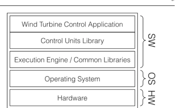
SW HW OS
Wind Turbine Control Application Control Units Library
Operating System Hardware
Execution Engine / Common Libraries
Fig. 1: HW/SW architecture of a Wind Turbine Control Sys- tem
Figure 1 shows the improved HW/SW architecture of the WTCS that enabled such separation of concerns. The two lower layers refer to the HW and the operating system. The software layer is composed of the following components:
TheExecution Engineis a component that cyclically exe- cutes the algorithms to monitor and control the wind turbine.
TheControl Units Librarycontains a set of reusable control algorithms. These are basic blocks, with well defined interfaces, which can be instantiated and interconnected to implement theWind Turbine Control Application. AWind Turbine Control Application (WTCA)comprises the
set of algorithms that must be executed in order to ensure the correct operation of the wind turbine the WTCS is monitoring and controlling. The control algorithms of the wind turbine are specified by instantiating control units available in theControl Units Libraryand by combining those instances.
In this software architecture, theExecution Engineis a stable software component which does not vary from one wind turbine to another. TheControl Units Libraryis also a stable component which, generally, does not vary either, unless some new device is used in a wind turbine and a custom control unit has to be implemented to control it.
Finally, the WTCA is the part of the software in a WTCS that is customized for each wind turbine, depending on the specific requirements that WTCS must met.
The development of a WTCS is a process whereby a multidisciplinary team of hardware, software and telecom- munications engineers, as well as electrical, mechanical and other engineers work in collaboration. However, since the top layer (WTCA) is the only part that is specific for each different wind turbine, this paper will only focus on the de- velopment of the WTCA.
In the late 2000’s, Ikerlan had already implemented dif- ferent solutions based on DSLs built on top of open-source tools, and more specifically, on Eclipse [94] and its Eclipse Modeling Framework (EMF) [89]. Based on this experience,
WT sysId : EString model : EString version : EString
SystemInput sysId : EString description : EString
SystemOutput sysId : EString description : EString SystemParam
sysId : EString description : EString value : EInt
settable : EBoolean = false
WTCInput WTCOutput
WTCParam Subsystem
sysId : EString description : EString
ControlUnit sysId : EString description : EString cycle : EShort priority : EShort enabled : EBoolean = false
MainSubsystem
ControlUnit15
[0..*] inputs [0..*] outputs
[0..*] params
[0..*] controlUnits
[0..*] subsystems
[0..*] subsystems
[1] Input__iInput1
[1] Output__oOutput1 [1] Parameter__pParam1
Fig. 2: Metamodel of the Wind Turbine DSL (excerpt)
the development of a new set of tools exploiting a domain- specific modeling tool for the development of control ap- plications for wind turbines – the so-called Wind Turbine Control Modeler (WTCM) – started, using Eclipse and re- lated open-source technologies. The WTCM provides the catalogue of availablecontrol unitsthat engineers can use to develop the algorithms to monitor and control the subsystems of the wind turbine.
The control system of a wind turbine is typically com- posed of almost 2000 basic control units, involving about 2000inputs and up to1000outputs, depending on the specific model configuration. A control unit is a basic and reusable control algorithm that may be combined with other control units to build more complex algorithms. The control system is structured into logical subsystems, each controlling differ- ent physical subsystems or parts of them. The control of a wind turbine is built through the aggregation of basic control units in order to specify those complex algorithms.
Figure 2 shows an excerpt of the metamodel, which describes the abstract syntax of the DSL provided by the
WTCM. As the figure shows, the control system of a wind tur- bine (WT) is a parameterizable element (viaSystemParam) that processes a set ofSystemInputsto obtain a set ofSyste- mOutputs. This control system contains a set ofMainSubsys- tems– a specific kind ofSubsystems3– and that in turn, con- tainControlUnits.Subsystemsmay also contain otherSubsys- temsfollowing the composite pattern.ControlUnits– which may be also parameterized usingWTCParams– implement the algorithms which process a set of inputs (WTCInput) to provide a set of outputs (WTCOutput). For the sake of simplicity, Figure 2 only shows an exampleControlUnit15, which processes a single input according to a single param, and produces a single output. As aforementioned, theCon- trol Units Libraryis a stable element which, in general, does not vary. As such, our Wind Turbine DSL contains a subclass extendingControlUnitfor each one of the reusable control algorithms we have in theControl Units Library.
3 We differentiate betweenMainSubsystemsandSubsystemsbecause, in our case study, the code generated for the former is inherently different from the code generated for the latter.
Fig. 3: Screenshot of Wind Turbine Control Modeler
Figure 3 shows what the initial implementation of the WTCM – which implements the Wind Turbine DSL – looks like. As it can be seen, the initial WTCM is an Eclipse application, which enables engineers to edit WTCS models using a regular EMF tree editor. This regular tree editor is a single-user editor designed to be executed in a desktop computer. Models created using this tree editor are stored as XMI [74] files.
Once a model has been created using the WTCM, the actual C++ code for monitoring and controlling the physi- cal subsystems can be generated using model-to-text trans- formations expressed in the Epsilon Generation Language (EGL) [57].
2.4 Measurable Benefits
The adoption of MBE practices facilitated coping with the inherent system complexity. One of the reasons was that the systems were specified in terms closer to the problem do- main, which gave engineers the ability to detect and resolve issues at that level, while separating them from the software implementation details. Thanks to the efficient separation of concerns in the improved platform, the knowledge about the system greatly improved among the engineers in charge of its development. As a result, there was a substantial gain in terms of efficiency and productivity: Ikerlan adopted the newly MBE-based solutions in a small group of develop- ers (around 5 persons), which from that moment on applied them to the development of 20 new systems with nearly 100 subsystems each. Other developers continued using the old manual approach. After measuring the time spent to specify the different models and generate the code for a WT, and comparing such time with the the time spent to manually code a similar WTCA in terms of complexity, the results showed that the time to develop a new WTCA targeted for a new product using MBE techniques was reduced from 240 weeks to only 15 for a junior engineer; while for a senior engineer was reduced from 60 to 15 weeks. These improve- ments where obtained in an incremental way, by refining the platform that had already been developed, and by taking advantage of the experience of the in-house developers.
3 Challenges
Today, MBE is used by a group of around 10 developers working in the R&D area of Ikerlan developing control sys- tems for new families of wind turbines. The aim of Ikerlan is to extend MBE technologies to other activities such as wind turbine control customization for specific customer re- quirements. Considering that there are more than 30 different variants of control applications that are still being developed
using non-MBE methodologies, it is expected that the num- ber of different models can grow significantly within the next years, increasing the number of developers using modeling techniques up to 20 or more in the mid-term.
This requirement poses a major challenge to the initial WTCM approach presented before, as it lacks the features that would enable a team of engineers to work collabora- tively: each engineer has to work with their own copy of the model, and model merging operations – e.g., to include changes performed by others – need to be carried out man- ually. This manual process is a complex, tedious and error prone activity that can take more than half an hour depending on the amount and type of changes made.
Another important limitation is that engineers do not have mechanisms to work with a subset of the model. That means that all engineers must always work with the whole model (which may add up to thousands of elements as described in the previous section), although a small subset of elements of the model can be sometimes enough to perform a specific modeling or validation activity.
Based on these limitations, the following challenges have been identified to improve the development of WTCAs:
1. Thefirst challengeis to move from a single-user model- ing tool built for an engineer to work in an isolated way, to a modeling tool enabling several engineers to work collaboratively and securely by sharing – possibly big – models located in a central repository.
2. Thesecond challengeis the ability to edit partial mod- els or model fragments. It should be noted that a typical wind turbine model contains thousands of control units.
Thus, the ability to edit partial models or model frag- ments allows each engineer to work with a specific part of the model (as opposed to the whole model), thereby easing modeling activities. Additionally, the use of model fragments allows minimizing the volume of data trans- ferred over the network and limits the number of merge conflicts.
3. Thethird challenge is to graphically display and edit WTCS hierarchical models. Graphical models are more expressive for this domain as they ease the identification of relationships between model elements. This is an im- portant enhancement with respect to the initial tree-based editor, where relationships have to be found using aux- iliary views of the editor. Such graphical models, may contain, again, thousands of elements. Thus, graphical editors handling such models must be capable of dis- playing big models while being usable. Such scalable editors should include additional features like filtering facilities, hierarchies of diagrams, etc. Figure 4 shows a mockup of what a graphical WTCM would look like.
4. Finally, thefourth challengeis to enable model editing using a lightweight mobile device – instead of a lap-
RotorSpeed CnvPressure NacelleHumidity
NacellePressure iPressure oActivation
iDisabled pUnderPressureLimit pOverPressureLimit
CnvPump TowerPump NacellePump NacelleChiller GeneratorCooler TowerPressure
INPUTSPARAMETERS
CnvUnderPressureLimit CnvOverPressureLimit NacelleUnderPressureLimit NacelleOverPressureLimit TowerUnderPressureLimit TowerOverPressureLimit
OUTPUTS
iPressure oActivation iDisabled
pUnderPressureLimit pOverPressureLimit
TowerPump::PumpCtrl ConverterPump::PumpCtrl
. . .
. . .
Fig. 4: Wind Turbine Control graphical modeling conceptual mock-up
top – to perform the modeling activities on site in the wind farm.
4 The MONDO platform
The goal of Ikerlan joining the MONDO project was twofold:
(i)to provide a real-world scenario where the scalable mod- eling technologies can be tested and evaluated; and (ii) to improve their development processes by introducing such techniques. It is worth noting that the fact that MONDO was being developed as an open-source platform was important, as one of our requirements was to continue using open-source MDE tools. The MONDO platform is the open-source so- lution4 for scalable modeling and model management de- veloped within the MONDO project. Its main purpose is to address the shortage of scalable and collaborative support in state-of-the art technologies within the MBE landscape.
It is composed by several components for the development of scalable Eclipse-based editors and DSLs, collaborative modeling, model indexing and scalable model transforma- tions and queries.
In what follows we describe these main MONDO compo- nents, focusing on the aspects that were relevant to Ikerlan’s implementation of its Wind Power infrastructure, and more specifically, on the components that play an important role in the solutions presented in Section 5 and the evaluation presented in Section 6.
4.1 Collaboration
TheMONDO Collaboration Framework5[23] is a set of server-side and client-side tools and services aimed at im- proving collaboration among multiple organizations as well as multiple professionals within a single organization.
4 Sources available athttps://github.com/mondo-project/
5 https://github.com/FTSRG/mondo-collab-framework
The framework offers two main avenues of improvement over the state-of-the-art. First,better securitythrough model- aware fine-grained access control of modeling artifacts. Sec- ond, better conflict management either (i) through simul- taneous multi-user model editing in online collaboration;
or in case of traditional offline collaboration, (ii) through rule-based model element-level locking to avoid conflicts, and(iii) through intelligent automated merging to resolve conflicts when they do occur.
In the following, we present a brief overview of chal- lenges as well as design decisions to address them, with the primary focus on access control features.
4.1.1 Motivation and challenges
Access control— The development of complex systems ne- cessitates intensified collaboration between distributed teams of different stakeholders (system integrators, engi- neers of component providers/suppliers, certification au- thorities, etc.), potentially employed by different compa- nies. However, such collaboration introduces significant challenges for access control management to protect the respective Intellectual Property (IP) of different parties.
For instance, the detailed internal design of a component needs to be revealed to certification authorities, but it needs to be hidden from competitors who might supply a different component in the system. Even within a sin- gle organization, export control regulations may prevent certain artifacts from being divulged to external com- pany offices. Furthermore, certain critical aspects of the system model may only be modified by domain experts with appropriate qualifications. For all these reasons, en- gineering artifacts must undergoaccess control. Model fragmentation and granularity— At the time the
development ofMONDO Collaboration Frameworkwas started, access control management in most existing col- laborative modeling repositories was still in a prelim- inary phase, supporting permission assignments only
globally, or using fragments (i.e. on the level of model files or projects). In order to share various parts of system models between collaborators, models needed to be split into a large number of static fragments (e.g. over 1000 for automotive models). Consequently, the re-fragmentation of the model (which may be necessary when collabo- ration roles, model contents or policy decisions evolve) is hard or infeasible. Therefore, static fragmentation be- comes both a scalability and usability bottleneck. Static fragmentation can be mitigated byfine-grained access control where each model element may have its own set of permissions. Unfortunately, large industrial mod- els may have millions of model elements, thus explicitly assigning permissions for each element would be labor- intensive and error-prone. Moreover, understanding and maintaining permissions after model changes can also be problematic.
Online and offline collaboration— System models are tra- ditionally developed either in an offline or online manner.
Inoffline collaboration, which is very common in cur- rent MBE practice, engineers check out an artifact from a repository into a local copy, work on their disconnected copy for an arbitrary duration, and then commit local changes to the repository in asynchronous (long) trans- actions. Inonline collaboration, engineers may simulta- neously access and edit a model in short synchronous transactions which are immediately propagated to all other users. This latter strategy is similar to online collab- orative office tools like Google Docs, and it is showcased in modeling tools like WebGME [64], AToMPM [20], GenMyModel / Web Modeling Framework [96] or Meta- Edit+ [99].
In the offline case, all information available to a specific user (accounting for read access control) needs to be provided as a self-contained model that can be displayed and edited by existing off-the-shelf modeling tools. Sim- ply hiding elements from the user interface of a desktop modeling tool is insufficient, as the IP is still accessible on the client side e.g. by file inspection. Hence, a filtered but modifiable model that excludes any confidential in- formation needs to be sent to each client. Furthermore, the online scenario requires immediate change propaga- tion, where model modifications need to be evaluated in an efficient, reactive way in response to the change; this change processing must account for write access control (is the user allowed to make this change?) as well as read access control (which other users are allowed to see the effects of this change?).
Conflicts and merging— Effective collaboration requires that engineers working simultaneously do not interfere with each other. This is traditionally achieved by par- titioning the model into fragment files and providing file-level locks; while object-level locks are also avail-
able in some systems. The former is too coarse-grained and thus prone to overlocking (needlessly preventing un- related edits), while the latter may be too fine-grained and may easily lead to accidental underlocking (where locks fail to prevent conflicting edits). Conflicts are es- pecially prevalent in asynchronous offline collaboration, where individual collaborators execute longer checkout- commit cycles, with a larger chance of conflicting edits happening in the meantime.
When conflicts do occur, the alternative versions have to be correctly merged. Computing differences, conflicts and merged resolutions is significantly more complex over MBE models with graph-based knowledge represen- tations (and complex well-formedness rules) than over textual source code. Inter-model dependencies make con- flicts surprisingly easy to introduce and hard to resolve.
4.1.2 Architectural overview
The central component of theMONDO Collaboration Frame- workis theMONDO Collaboration Server [10], which en- forces fine-grained access control during both offline and online collaborative modeling. The server provides secure views with precisely defined model access to each collabo- rator, synchronized with each other bybidirectional model transformations[25]. In particular, a transformation applies read access restrictions to present a filtered view to a user, while a separate transformation merges changes proposed by a user into the unfiltered model (if write access restrictions allow); both transformations are automatically derived from the declared access control policy.
In the offline collaboration scenario, the server hosts models in a version control system (VCS). However, tra- ditional source code repositories cannot address the chal- lenges associated with fine-grained access control of models.
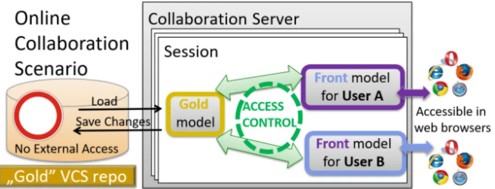
TheMONDO Collaboration Serverprovides multiple user- specific version histories instead, which are all synchronized with each other; see the architecture depicted in Figure 5. The full and unabridged model is versioned in the so-calledgold repositorywhich is inaccessible to the actual users. There is also a separatefront repositorydedicated to each user, that contains a copy of the gold repository, with complete ver- sion history (black vertical arrows in Figure 5), where the contents of each version snapshot is filtered according to the read access privileges of that user (see solid green horizontal arrows in Figure 5). Users are given access to a dedicated front repository so that they can read the current or histor- ical contents of the model files (up to their read privileges) and commit their changes (which may be denied based on write permissions). In case changes (see dashed arrows in Figure 5) are successfully committed, they are transparently propagated to the gold repository (blue dashed horizontal ar- row), and then, by the usual filtering, to the front repositories
Fig. 5: Overview of access control (offline collaboration)
Fig. 6: Overview of access control (online collaboration)
of all other users (green dashed horizontal arrow). In their normal day-to-day workflow, users interact with their front repository using standard VCS protocols and off-the-shelf VCS client software.
For anonline collaboration scenario, MONDO provides an online collaborative modeling tool, where users can open, view and edit models stored in the VCS backends using a web browser, thus no client software needs to be installed.
As depicted in Figure 6, multiple users can collaborate on the same model simultaneously, enjoying the same access control mechanism that underlies the offline collaboration framework. The editor is provided as an Eclipse RAP-based web application [95]; note that the model editing Web UI is language-dependent, and thus has to be provided separately for each supported modeling domain.
4.1.3 Query-based access control
As argued before, security needs a fine-grained access con- trol mechanism that must determine the permissions of each model element in the model. It would be possible to adopt a low-level specification method, i.e. require engineers to manually assign security permissions to each model element, each attribute slot value and each cross-reference. However, industrial wisdom (see e.g. the survey [98], itself citing sev- eral older surveys in the field) advises against such a solution, and advocates for "high-level specification of access rights"
instead. Indeed, the low-level approach suffers from the fol- lowing difficulties:
– the necessary per-element permission annotations would form a large amount of additional user input;
– manually specifying and correctly maintaining them ac- cording to organizational security policies would put an undue burden on each collaborating specialist that edits the model;
– as such a large amount of security-critical user input, they would be prone to contain errors (with business-critical consequences) that are difficult to test for in an automated fashion;
– overseeing them and auditing them for conformance with organizational security policies would be labor-intensive for security officers.
We have therefore chosen a high-level alternative for specifying access rights. A rule-based approach for con- cisely defining fine-grained model access control policies has been proposed in [10], where a single rule may grant or deny permissions for many elements in a model selected ac- cording to amodel query. AMONDO Access Control Policy combines individual rules with various priority classes, in addition to applying sensible defaults, according to seman- tics defined in [24]. An incremental evaluation mechanism was provided in [11] so that the access control policies can
be reactively applied after each single editing operation in the online collaboration scenario.
The key distinguishing feature ofMONDO Access Con- trolfrom (non-model-based) standard rule-based policy lan- guages (such as XACML [43]) is that it applies to models.
Therefore, it uses expressive model queries (graph patterns) to identify the model elements to which the rules of the policy are applicable. Furthermore, it ensuresreferential in- tegrityof the model throughout the interactions of rules, so that the filtered local copies provided in the offline scenario are consistent, if incomplete, models.
4.1.4 Locking and merging
TheMONDO Collaboration Frameworkimplements a novel property-based lockingtechnique introduced in [26], which is a common generalization of several widely used lock- ing approaches. Property-based locks can be used to pro- tect model editing operations (including complex refactor- ings) by capturing their pre-conditions as a declarative query.
The lock forbids other users from concurrently changing the model in a way that affects the result set of the query, thereby violating a precondition of the lock owner. The MONDO Collaboration Server applies locks analogously to access restrictions.
Nevertheless, conflicts occasionally do occur and have to be merged. The framework includes a client-side tool called DSEMerge [27] – and seamlessly integrated into Eclipse- based client modeling environments – that performs auto- mated search-based model merge. The tool computes and displays possible candidate resolutions (conflict-free merged models) for a conflict, from which the user can select the most suitable one. In the fortunate case where there are no conflicts between element-level changes (even if there was a file-level conflict), the tool comes up with a single "perfect" solution candidate that includes all changes, so that the user does not even have to choose, but merely approve. Otherwise, choos- ing a solution is assisted by several summary metrics such as the number of elements deleted, number of changes included in the solution, etc.
More precisely, the tool identifies the set of individual model editing operations on the two branches to be merged (since the last common ancestor), and automatically pro- duces the set of "maximally merged" conflict-free states that cannot be extended further by including more of these edit- ing operations. The developer of the modeling language may provide additional domain-specific insights to further im- prove this mechanism. By default, the solution candidates are constructed by breaking down the overall model differences into atomic edit operations (e.g. modify attribute, delete ob- ject), but this may be overridden if complex domain-specific semantic edit operationsand resolution rules are provided.
Furthermore, beside obvious hard contradictions (e.g. as-
signing different values to the same attribute), the notion of "conflict" may include domain-specificwell-formedness rulesas "soft goals". The automated generation of candidate solutions may also take into account a distinction between essential and incidental modifications, e.g. a core design decision vs. simply rearranging a diagram; obviously, the former kind is prioritized over the latter.
4.2 Model indexing
Hawk6is amodel indexer: it keeps an up-to-date read-only view of model collections (aka amodel index) and facilitates performing efficient queries on them. Hawk monitors local or remote data locations (such as local file directories, ver- sion control systems like Git or SVN or remote URLs) and periodically synchronises itself with model files of interest in these monitored locations.
4.2.1 Using Hawk as part of the MONDO Platform Hawk enables scalable queries on models in the MONDO platform. By querying model indexes of such models (in- stead of the originating model fragment files), the MONDO platform is able to perform various read-only operations in a scalable and incremental manner. For example, a graphical editor needing to display parts of a very large EMF model is able to query Hawk for the subset of model elements it currently needs to display, hence visualizing it in a more efficient way (in terms of time and memory use) than if it needed to load the entire model from its originating frag- ments. This can be extended to queries performing arbitrary computations on parts of large fragmented models (such as the ones created by Ikerlan), as such queries can execute without having to load, resolve or navigate through the parts of the model they are not interested in. Further information on Hawk, including its updating and querying policies, can be found in [5, 6, 7, 38].
4.2.2 Architectural overview
Figure 7 shows an overview of Hawk, focusing on how its components interact to maintain an up-to-date model index:
Version Control Managers— Specific for each version con- trol system (VCS), these components need to compute the set of changed files (added, removed or updated) relative to the revision last indexed by Hawk (and the current latest version in the VCS).
Model Resource Factories — These components offer parsers for reading from specific model persistence for- mats, like EMF models persisted in XMI or Modelio [66]
6 https://github.com/mondo-project/mondo-hawk
Fig. 7: Component architecture of Hawk
models in XML. Such parsers take as input the contents of files (provided by version control managers) and pro- duce as output a uniform in-memory representation (“re- source”) of such models.
Model Updater— This component receives resources cre- ated by the appropriate model parser(s), and inserts/up- dates them into Hawk’s persistence (database), through back-end specific drivers. The structure of these stores assumes that such back-ends provide a mechanism for rapidly accessing specific elements using a key (aka database indexing). This is the case for many popular stores such as MySQL, MongoDB or Neo4J, which in- clude their own embedded database indexes.
Query Engine— This component provides a bridge be- tween Hawk and any model management tools querying it. Queries can be performed on both local and remote Hawk model indexers and can return textual or numeric results, as well as collections of model elements.
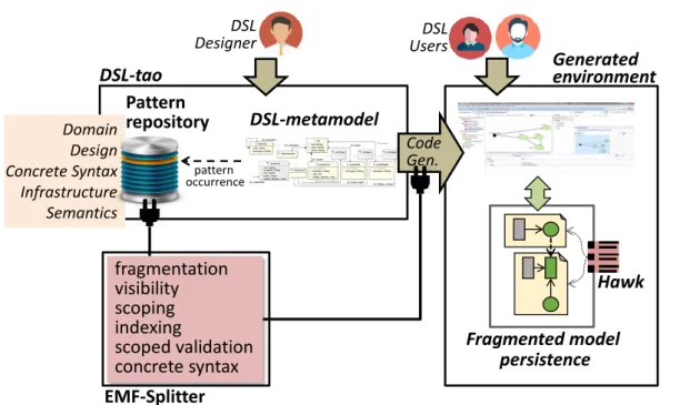
4.3 Pattern-based scalable DSLs
DSL-tao7 [80] is the component within the MONDO plat- form that enables the systematic development of scalable graphical DSLs based on EMF. Its working scheme is de- picted in Figure 8.
DSL-tao supports the systematic creation of DSLs by reusing patterns. It supports 5 types of patterns, covering the different aspects of DSL design: domain, design, infrastruc- ture, semantics and concrete syntax. The patterns either help in designing the metamodel (e.g., design and domain pat- terns), or contribute with services for the final environment (e.g., infrastructure, semantics and concrete syntax). This way, DSL-tao profits from an extensible library of metamod- eling patterns, which are instantiated and combined when building a DSL. Some of the currently supported domain patterns (e.g., for variants of state machine, workflows, ex-
7 https://github.com/jdelara/DSL-tao
Pattern repository
Designer DSL
Domain Design Concrete Syntax Infrastructure Semantics
DSL-tao
DSL-metamodel
pattern occurrence
fragmentation visibility scoping indexing
scoped validation concrete syntax EMF-Splitter
DSL Users
Generated environment
Fragmented model persistence
Hawk
CodeGen.
Fig. 8: Working scheme of DSL-tao
pressions, etc) were extracted from the analysis of existing metamodels in public repositories [80].
DSL-tao provides extensibility mechanisms, so that new patterns can be added to its repository. A new pattern can contribute its own wizard to facilitate its instantiation, and with services (realized by code generation) to contribute functionality to the final modeling environment. This way, a number of infrastructure patterns have been created, to define modularization strategies for DSLs, including pat- terns to define fragmentation strategies (so that models are not persisted in a monolithic way), visibility (to define ac- cess rules for model elements), scoping (to specify reference scope), filtering (to select interesting objects) and graphical concrete syntax support, among others. The application of these patterns, and their associated services are contributed by EMF-Splitter8 [41], a tool that can also be used stand- alone. The generated environments rely on Sirius for graph- ical model editing, while Hawk [4] – the MONDO model indexer – is used for efficient look-up of models element across fragments.
In the following, we explain the different parts of the approach: the pattern structure and application process (Sec- tion 4.3.1), the modularization patterns (Section 4.3.2), and the concrete syntax pattern (Section 4.3.3).
4.3.1 DSL Patterns
Our DSL patterns have the form of a metamodel, which is conceptually located one meta-level higher than the domain metamodel being built. The elements of a pattern are called roles[60].
To apply a pattern, its metamodel is instantiated and then integrated into the existing domain metamodel. This integra- tion requires first a mapping from the roles in the pattern instance to the elements in the domain metamodel. Once this identification is made, an automatic merge operation adds to the domain metamodel the roles in the pattern that are not mapped, and annotates the metamodel elements with the pattern roles.
Figure 9 illustrates the scheme of pattern application.
Label 1 depicts a simple metamodeling design pattern de- scribing tree structures [13]. The pattern has two class roles (TreeandNode), two reference roles (rootandchildren) and two attribute roles (orderedandident). Theorderedattribute role is a configurationattribute (indicated using the “@1”
potency annotation [2, 61]), meaning that it takes a value when the pattern is instantiated, rather than being mapped to an attribute in the domain metamodel.
In Figure 9, label 2 shows the pattern instantiation the metamodel designer has chosen, where two instances ofchil- drenandidenthave been created. Label 3 shows an excerpt of a domain metamodel the designer is working on. To apply
8 https://github.com/antoniogarmendia/EMF-Splitter
Tree
root 1 Node
1..*
pattern
ordered@1: bool
ident: String
:Tree
:root :Node pattern
instance
2
ordered= true
:ident: String :ident: String 0..*
1
children
* 1..*
: children : children
WT Subsystem
Versioned version: String
1
sys ctrl *
3
WT
Subsystem sysId: String
Versioned version: String
sys
ctrl * aux
«ident»
«Node»
«root»
«children» «children»
«Tree»
«ident»
domain MM
mapping
4
…
… updated
domain MM
Fig. 9: Scheme of pattern application.
the pattern, mappings between the pattern instance and the domain metamodel need to be established. Our mechanism supports structural matching, so that, e.g.,identinNodeis mapped toversionin classVersioned. As the Figure shows, the merge operation creates the elements not mapped in the pattern instance in the domain metamodel, and annotates the domain metamodel elements with the pattern roles. The cre- ated elements take by default the name of the role element, but this name can be changed when the mapping is being defined (as in case of the example). When the pattern is ap- plied, if an element with same name already exists in the metamodel, a new name is generated (concatenating a nu- merical index). Other conflicts (e.g., inheritance cycles) are automatically detected either when the mapping is created, or when the pattern itself is applied. In both cases, an error is reported, and the engineer is asked to change the mappings.
It must be stressed that the pattern may bring services to the generated domain-specific environment, for example, constraints ensuring a proper order in case of ordered trees, and operations ordering the tree according to the selected identifiers. By defining these services on the pattern, they become reusable for any metamodel where the pattern is applied. Moreover, this approach also brings benefits when the DSL evolves. In this case, the designer needs to change the mappings to accommodate the change, and regenerate the environment again with the updated service provided by the pattern. This way, the service code does not need to be changed by hand, but only the mappings need to be modified. If the services would have been defined directly on the domain metamodel, the designer would have needed to manually modify the code implementing the service, which typically would require more effort.
While role cardinalities support the customization of a pattern for a given context, our patterns also support more coarse-grained variation. For example, in case of trees, in
Project Package
<<abstract>>
Container
<<abstract>>
Containee 0..*
contents
(a) (b)
<<Project>>
WT sysId: EString<<name>>
icon=“wt.png”
<<abstract>>
IdentifiableElement name: Estring icon@1: Path
<<Unit>>
SystemInput
<<Unit>>
SystemOutput
<<Unit>>
SystemParam icon=“sys-i.png”
extension=“input”
extension@1: EString Unit
icon=“sys-p.png”
extension=“param”
icon=“sys-o.png”
extension=“output”
icon=“subsystem.png”
extension=“sub”
<<Unit>>
<<Package>>
Subsystem sysId: EString <<name>>
subs 0..* subs
0..*
0..* 0..*
inputs outputs
params
0..*
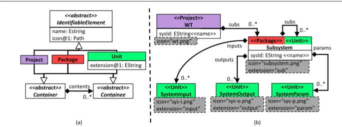
Fig. 10: (a) Fragmentation modularity pattern (b) Applying the fragmentation pattern to the WT metamodel.
addition to the simple structure shown in Figure 9, we may have structured trees (enabling the differentiation of leaf and non-leaf classes, leading to a structure similar to the com- posite pattern [37]), trees changing over time, or overlapping trees (whose nodes may share a parent node), among oth- ers [13]. This way, we support pattern variants, which are selected through a feature model [51].
4.3.2 DSL modularization patterns
In MDE, models are the main assets used to create soft- ware. However models frequently lack native modularization mechanisms, unless they are explicitly encoded in the mod- eling language and implemented in the supporting modeling environment. Thus, we have devised a number of patterns to provide modularity services to the DSL environments. In this sense, we follow a similar philosophy to the Java Devel- opment Tools (JDT). In this way, each model corresponds to an Eclipse project, and the model content will then be fragmented into units, and organized in folders, with a direct mapping to the file system.
The main pattern to achieve this modularity is the frag- mentation pattern, shown in Figure 10 (a). This pattern de- finesProject,Package andUnitas classes roles. Language engineers can configure which classes in the domain meta- model will play those roles. For example, typically the class that is mapped toProjectwill be the root class in the meta- model (the one that directly or indirectly contains all the other classes). As a result, each time this class is instantiated in the generated environment, a new modeling project (i.e., a folder that will hold all fragments of the model) is produced.
Similarly, when a class with rolePackageis instantiated, the environment creates a folder in the file system, together with a hidden file storing the value of the class attributes and non- containment references. Finally, instantiating a class with Unitrole results in the creation of a file that holds instances
of the classes that can be directly or indirectly reached by means of containment relations.
The application of the fragmentation pattern to the WT metamodel is shown in Figure 10 (b). TheWTclass has been assigned roleProject, whileSubsystem has been assigned rolesPackageandUnit. This means that withinWTprojects we can find both, folders and files to represent subsystems, and the model developer chooses which representation is desired. Finally, classesSystemInput,SystemOutputandSys- temParamare assigned roleUnit.
Hence, altogether, by using this pattern the DSL designer can devise a suitable fragmentation strategy for the DSL, so that models are no longer monolithic, but fragmented and structured according to the chosen strategy. Technically, we rely on EMF crossreferences to realize references across fragments. These are based on the creation of proxy objects, which are only resolved when the reference is navigated.
Moreover, the environment uses Hawk to optimize the han- dling of the different model fragments.
4.3.3 DSL concrete syntax patterns
In our approach, the concrete syntax of the DSL is defined by applying patterns as well. Two patterns are currently sup- ported, to visualize the models in the form of graphs (graphi- cal syntax), or tables (tabular syntax). These concrete syntax patterns enable the creation of language families with similar representations. In the case of graphical syntax, we support the definition of nodes, edges and spatial relationships be- tween elements for visualization in a graphical editor. The concrete syntax patterns can be used to automate the gener- ation of editors supporting the defined syntax (which other- wise should be implemented by hand), and can be attached to domain (e.g., the state machine pattern [80]) or design patterns (e.g., the tree pattern) in order to define different default visualization options for them.
GraphicRepresentation name: String
Layer name: String
1..*
layers defaultLayer
1..1
<<abstract>>
DiagramElementType
EdgeClassType NodeType diagElements
0..*
Shape 0..1 spatialRelations
Ellipse width: Integer height: Integer
Rectangle width: Integer height: Integer
Figure filePath: String edgeStyle
EdgeStyle decorator: String width: Integer
0..1
<<abstract>>
SpatialRelation 0..*
Containment Affixed
EdgeReference width: Integer height: Integer
edgeReference 0..*
0..1 edgeStyle
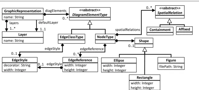
Fig. 11: Excerpt of theGraphicRepresentationmetamodel
The application of the concrete syntax must map the classes in the domain metamodel to a graphical element.
This process has many specificities (like selecting figures for nodes and decorators for edges), that is why we imple- mented a dedicated wizard to facilitate this task (shown later in Figures 13 and 14). For instance, the customized wiz- ard implements heuristics to decide which classes will be represented as nodes, which ones as edges, the attributes to display, and the nodes that are containers of other nodes.
Then, the designer can refine the inferred concrete syntax and fine-tune the visual representation for nodes and edges, using the pattern wizard.
The wizard allows customizing the heuristics that best suit the metamodel for which the environment is generated.
The heuristics analyze the classes and references defined in the metamodel and infer a visual representation. For example, to choose the root node there are two strategies: choosing the class that contains more children (classes) or the class that does not have parents. The first strategy counts how many classes are contained in each class and selects the one that contains more. The second strategy suggests classes that are not contained in other classes. Both strategies are based on the tree of containment references defined in the metamodel.
With respect to edges, our heuristics support selecting edge-like classes and references as edges. In the first case, we select the classes that define two non-containment references with lower bound 0 or 1, and upper bound 1. These two references will be mapped to the source and target of the edge representation for the class. In second case, the heuristics identify the references that will be displayed graphically as edges, compartments or affixes.
We consider abstract syntax metamodels defined in Ecore, for which the concrete syntax can be established according to Figure 11. In particular, classes in the domain metamodel can be represented either as nodes (classNodeType) or as
edges (classEdgeClassType) and are referred to through the classDiagramElementType. In case the class is represented as an edge, it is possible to configure the references of the class acting as source and target of the edge. References in the domain metamodel can be mapped intoEdgeRefer- ences, and their concrete syntax annotations are mapped into anEdgeStyle. All created graphical elements are included in the default layer.
Technically, the concrete syntax pattern relies on Sirius.
This way, once the pattern is applied, the generated modeling environment will automatically feature Sirius-based editors to edit the different model fragments.
5 MONDO Solutions for Offshore Wind Power
Using the previous core MONDO infrastructure, three mod- eling solutions have been implemented in Ikerlan. These three modeling solutions aim to cover the different scenarios showing up in Ikerlan (see Section 6.1), where the challenges listed in Section 3 emerge. Next we describe these solutions, whose sources and demonstrators are also available online9.
5.1 The Online Concurrent WTCS Modeling Solution TheOnline Concurrent WTCS Modeling Solutionis a web modeling application that allows multiple modelers to share a modeling session. All modelers can work concurrently with the same WTCS model versioned in a model repository. All changes performed by a modeler are automatically propa- gated to all other modelers, constantly providing them with an up-to-date version of the model.
9 https://github.com/mondo-project/mondo-demo-wt
Besides allowing concurrent modeling activities, this so- lution also supports working with partial models. It means that each modeler can work with a different view of the same model, thus editing a different fragment of it. This feature is possible thanks to the model access rules, which can be defined by using the model access control policy lan- guage provided by theMONDO Collaboration Framework (see subsection 4.1). This is achieved by creating a custom model view containing only the model elements a user is al- lowed to see and edit, hiding all other elements in the model.
Unauthorized editing of model elements is also prevented as a consequence of using this process. TheOnline Concur- rent WTCS Modeling solution allows modelers to commit the changes performed in the model to the model repository.
The Online Concurrent WTCS Modeling Solutionis a web application that can be accessed both from desktop com- puters and mobile devices. Each in-memory model session is managed by the MONDO Collaboration Server, which transparently enforces the model access rules by(i)filtering the content to be presented in the web-based model editor to each of several simultaneously connected users and(ii)inter- cepting their model edit operations for write access control and propagation to the views of other users10.
5.2 The Offline Collaborative WTCS Modeling Solution The Offline Collaborative WTCS Modeling Solution is an Eclipse-based modeling application that runs locally. It en- ables several engineers to work with a shared model, but unlike the solution presented above, collaborative modeling is done asynchronously, i.e., each modeler working with the shared model edits a local copy of the shared WTCS model, which is checked out (or updated) from a model repository.
When model editing has finished – or whenever the user de- cides – a commit operation is requested and theMONDO Collaboration Servercarries out the operation.
From the perspective of engineers using the modeling platform, the main difference between the offline and online modeling solutions is that the offline solution allows the user to check out a disconnected, persisted copy of the model.
This local version can then be processed by legacy or off- the-shelf MBE tooling. The user has to explicitly commit any local changes to the server, and merge with changes that may have been performed in the mean time. This is aided by a full version history maintained on the server, providing a standardversion control repositoryinterface for client-side or server-side tooling to interact with.
Access control restrictions, imposed by the same policy introduced above, are of course enforced in the offline solu- 10 For more information and screenshots about theOnline Concurrent WTCS Modeling Solution(Section 5.1) and theOffline Collaborative WTCS Modeling Solution(Section 5.2), refer to the public MONDO deliverable [97].
tion as well. This is achieved by introducing access-filtered replicas of the version control repository hosting the models.
There will be a separatefront repositoryfor each different user role and it will contain the (version history of the) filtered partial model for that user role. TheMONDO Collaboration Serverwill be in charge of keeping synchronized all the front repositories with the so-calledgold repository(hidden from users), which will always contain the whole WTCS model.
This synchronization will be done when any commit oper- ation is carried out. For synchronizing the gold repository and all the front repositories, model access rules described above will be used by the MONDO Collaboration Frame- work, to take into account the permissions each user will have to access and edit model elements. This way forbidden model editing operations will be detected by theMONDO Collaboration Framework before any commit operation is performed and the commit requested by the modeler will be rejected.
As aforementioned, in MONDO, the management of par- tial models in an offline manner is handled by theMONDO Collaboration Server(see subsection 4.1) which performs the synchronization between all the front repositories and the gold repository; there exists a different front repository for each different user type which contains the partial model for that user type. The modeling client, therefore, only needs to include an off-the-shelf VCS client in order to be able to participate (by communicating with their dedicated front repository using standard VCS protocols).
However, for more efficient handling of conflicts, theOf- fline Collaborative WTCS Modeling Solutionis additionally bundled withDSEMerge[27] (see subsection 4.1), which is the MONDO solution for automated model merging.DSE- Mergemay be customized for each modeling language by domain-specific operations and well-formedness constraints in order to reduce the search space and obtain accurate merged models (that are semantically consistent as well).
Such operations and constraints should be defined only once for a given domain, and not once per each merge activity.
In case ofOffline Collaborative WTCS Modeling Solution, we specified no domain-specific operations, and only ap- plied the following custom well-formedness constraints: it is mandatory that all SystemInput and SystemParam instances should be referenced by at least one control unit and each SystemOutput has to be referenced by a unique control unit.
Apart from collaboration related operations, the way a model user will work with theOffline Collaborative WTCS Modeling solutionis quite similar to the way the modeler was working with the tree-based single user modeling tool introduced in Section 2.3: in summary, the engineers will now have all the features that will allow them to work in collaboration with other engineers but without having to change the way they were used to.
Fig. 12: Graphical editor for Offline Collaborative WTCS Modeling solution
Fig. 13: Applying the Graph-based representation pattern
5.3 The Offline Graphical Collaborative WTCS Modeling Solution
The Offline Graphical Collaborative WTCS Modeling So- lutionis a Sirius-based editor, which allows editing WTCS
models graphically, as depicted in Figure 12. As mentioned above, WTCS models edited by the offline modeling solution are built with the Wind Power domain specific tree editor, but, as mentioned in Section 3, an important challenge is the capability of editing WTCS models graphically, with an ed-
Fig. 14: Shape selection and visualization details
itor that provides advanced features like drill-down, element filtering, layers, custom views, different diagrams, etc.
This challenge has been addressed by integrating a Sirius based graphical editor in the Offline Collaboration WTCS Modeling solution. This way, the same model (and model fragments) that can be edited by the EMF based tree editor and the graphical editor based on Sirius, taking advantage of all the functionality Sirius provides. Both client modeling perspectives enjoy the same collaborative features.
It must be noted that the ability to edit models using graphical diagrams based on Sirius is not a contribution of MONDO project, but a contribution of the developer team of Sirius. As the MONDO project was progressing, Sirius has become one of the most widely used Eclipse components to build graphical EMF-based model editors. For this reason it was decided to use Sirius for addressing the challenge of editing graphical models in this Wind Power use case. Hence, the MONDO project has been focused on facilitating creation of and integration with Sirius based modeling editors.
Taking this into account, we integrated thegraph-based representationconcrete-syntax pattern explained in Section 4.3.3 into DSL-tao in order to simplify the process of con- struction of this kind of editors based on Sirius. Although
Sirius provides its own tools to design graphical editors, this design activity carried out using Sirius design tools can be time consuming, and thegraph-based representationpattern aims to make this process much more simple to the DSL designers, hiding low level details of Sirius graphical speci- fications, which must be taken into account if design is car- ried out using Sirius design tools. Therefore, we designed the graphical concrete syntax for the wind power DSL using the graph-based representation pattern provided by DSL-tao.
This design pattern provides a wizard-based design process.
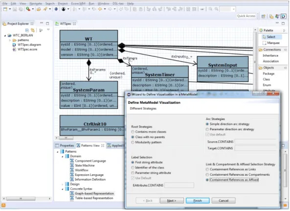
The steps followed to build the graphical syntax are shown in Figures 13 and 14.
The first step consists in selecting the pattern through DSL-tao, as shown in Figure 13. This Figure shows the main DSL-tao canvas in the background, with the DSL metamodel, and a pattern view that permits browsing and selecting the patterns to be applied to the metamodel.
It shows the first page dedicated pattern wizard, which allows the combination of heuristics to automatically gener- ate a graphical representation for the metamodel. The wizard offers different heuristics for the automatic selection of aroot class representing the diagram (boxRoot strategies). In this case, we use theClass with no parentsto select the class that