Saber M. Abd-Rabbo A.–A. Ibrahim
Lecturer, Mech. Eng. Dept., Shoubra Faculty of Engineering, Zagazig University
AN INVESTIGATION FOR THE AXIAL VIBRATION DURING TURNING AND ITS EFFECT ON THE
WORKPIECE SURFACE
Abstract
This paper presents the effect of axial cutting force, which arises during cutting process due to workpiece whirling and cutting conditions on the dynamic displace- ment (vibration), at constant axial tail stock clamping force.
A mathematical model has been proposed and solved analytically. The model studied the effect of axial forces (axial cutting forces and constant axial tailstock clamping force), with different workpieces dimensions and cutting speeds on axial vibration via simulation.
A set of experiments were carried out to study the effect of cutting conditions with a constant tailstock clamping force on the axial vibration amplitude arises dur- ing turning and consequently on workpiece roundness.
The results show that, at a certain tailstock clamping force there is a great de- pendency of axial vibration on cutting speed, workpiece length, and diameter. The increase of cutting speed diminished the effect of tail stock clamping force on the workpiece roundness error.
Introduction
Turning: is one of the most common used machining processes. The dimensional accuracy and workpiece roundness are of primary importance and directly affected by dynamic displacements (vibration) which arise during the cutting process [1].
The dynamics of the relative motion between the cutting tool and the workpiece affect directly both the quality and productivity of metal cutting [2]; hence it reduces tool life, prevents a machine tool from operating at its full capacity, and deteriorates the quality of the workpiece surface. Therefore, it has been subjected to continuous research over the last decades. Most of this work has been focused on machine tool chatter, i.e. self-excited vibration that usually developed during large metal removal rates. This phenomenon has detrimental effects on the workpiece accuracy.
Analytical solution of vibration of a rotating shaft was proposed by Yan et al [3].
R. G. Parker [4] developed the dynamic equations of motion for disk spindle sys- tems and suggested analytical vibration model, which depends on inertia, elastic bending and rotational stiffness.
Kato et al [5], studied the influence of tailstock center on the workpiece round- ness. They studied the transferring characteristics of roundness error from the center and center hole to machined surface in grinding.
Problem Formulation and Software Inputs
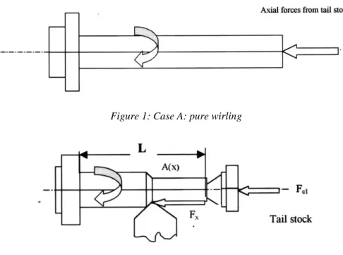
Rotating body was assumed to be rigid. In practice, however, all rotating bodies are flexible and therefore tend to bow out at a certain speed, and whirling in compli- cated manner. By considering a rotating workpiece on a lathe, between headstock and tailstock as shown in Figure 1. Before the single point tool approached to the workpiece, the workpiece was rotated at a certain speed, hence one can define pure whirling case (A) shown in Figure 1, as well as after the single point tool was start- ed to cut the workpiece semi-whirling case (B) can be defined as shown in Figure 2.
Figure 1: Case A: pure wirling
Figure 2: Case B: Semi wirling
Figure 1 simulate a case (A) of pure whirling for a rotating flexible workpiece that tends to bow out at a certain speed with a certain eccentricity "r". The generated centrifugal force causes a radial and axial displacement or vibration. During the cutting process, and due to the application of a single point tool, the whirling was generated in one side and the tool resists the whirling in the tool side "semi- whirling", case (B). In this case vibration in radial direction will be reduced and the vibration in axial direct will be increased. The axial vibration has a noticeable effect on the machine spindle and feed box mechanism.
To study the effect of axial vibration on workpiece/lathe performance, a mathe- matical model of the workpiece between the headstock and the tailstock during the cutting operation was proposed.
By considering an elastic workpiece of length "1" with varying cross sectional area A(x) as shown in Figure 2. The force acting on the cross sections of a small element of workpiece can be written as
x EA u
F
Fex
x u EA t
u
1
2 2 2
2
Where;
E is the young's modulus,
u is the axial displacement,
Fex is the external force per unit len~rth,
Hence with a boundary conditions of u(O,t)=0, u(l,t)=0
and an initial conditions of u(0,0)=0,
u( x,0)=1. x-2.x/1. (x-1/2 )
1 2
c p
c r m F
F
Where;1 =Fc / EA,
2 =Fx / EA
Fc is the Total axial force,
Fc1, is the tail stock axial clamping force, Fx is the axial component of cutting force
Theoretical Results (Software Outputs) and Discussion
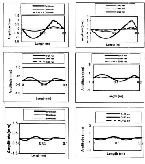
By considering a constant tail stock clamping force, the variation of workpiece diameter (20 mm, 40 mm, and 60 mm) with the same lengths of 100 mm, on the first three vibration modes at turning speed of 800 r. p. m. is shown in Figure 3a. It is noticed that the vibration level of the same mode of vibration is high when turning the workpiece of smallest diameter, while the vibration level decay at higher diame- ters. The vibration amplitude is high at the first mode, which show one node, while, at the third mode of vibration the number of nodes is increases while the vibration level decayed.
Figure 3: Vibration amplitude with the workpiece diameters at different modes The variation of workpiece diameter of (20 mm, 40 mm, and 60 mm) with work- piece length of 200 mm on first three vibration modes during turning at a same speed of 800 rpm. is shown in Figure 3b, which shows similar trends, but with a vibration level higher than that of workpieces of length of 100 mm.
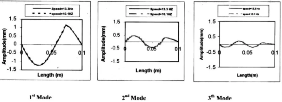
The effect of cutting speed value during turning a workpiece of length 100 mm is shown in Figure 4, which indicates that there is no noticeable difference on vibra- tions level due to change of speeds from 610 rpm. to 800 pm. at the first mode and
has the same vibration level at the later modes of vibrations with a noticeable reduc- tions.
Figure 4: Variation of vibration amplitude with cutting speeds
Experimental Work
The experimental work is focussed to study the effect of the cutting speed and the axial clamping force on the dynamics of turning operation. Three specimens were turned on a center lathe. Each specimen was clamped in a three jaw chuck and guided by a tailstock with a specified tightening force. This force was adjusted with a torque arm key. The value of the force was selected as that, in the range that cause the vibration level starts to increase with the increase of the value of the force [6].
Figure 5: The specimen under test
The specimen material is St. 42 with 20 mm diameter and 100 mm length. Eacll specimen was turned in two locations A and B as shown in Figure 5.
The cutting conditions were – Feed rate = 0.16 mm/rev.
– Depth of cut = 0.8 mm
– Cutting speeds are 38, 48, and 52 m/min.
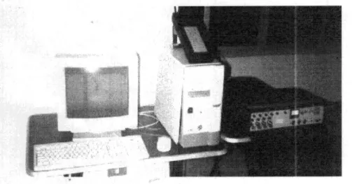
The axial tailstock tightening force was 10.3 KN. The vibration signals were measured during turning in radial and axial directions with B&K 7007 tape recorder.
The recorder signals were fed back to B&K 7107/2526 system for analysis.
Figure 6: Vibration measurement/analysis system
The vibration measuring system is shown in Figure 6. This system consists of data collector tape B&K 2526 and SENTINEL software package. The vibration spectrun was drawn.
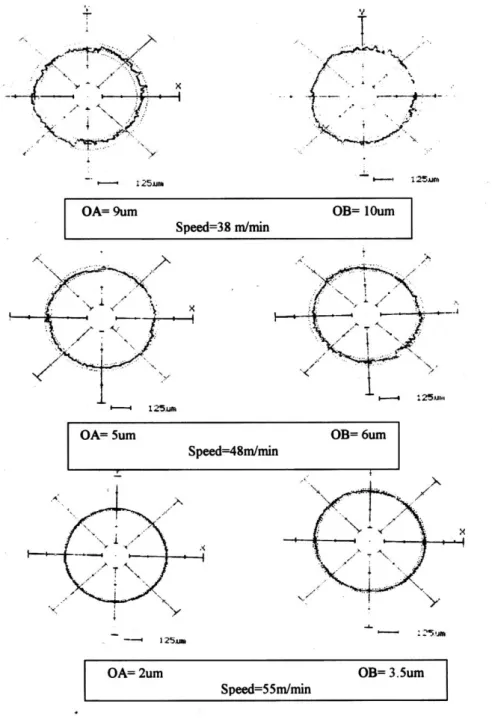
The roundness error of machined surfaces was measured using Talyround type MITUTOYO RA-112. Average of four readings for roundness error of the machined surfaces was calculated.
Experimental Results and Discussion
The experimental work was carried out according to the above-mentioned plan.
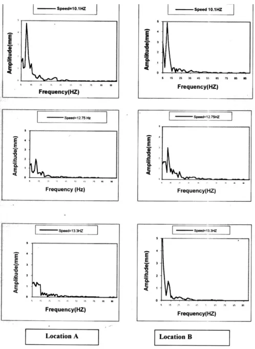
The results of vibration measurements show that, a good correlation is obtained with those measured in the axial direction than that of radial direction. The vibration spectrum for the signals that recorded during turning the three specimens are shown in Figure 7. The roundness errors on the workpiece surface are also shown in Figure 8.
There is no significant variation of RMS value for the obtained signals, this may be attributed to that. The root mean square (RMS) measures the overall intensity of vibration signal. So in this discussion attention is paid in Figure 7 for the amplitudes of vibrations as displacement versus frequencies. The amplitudes of vibration in mm are measured for each signal at the frequency of workpiece rotations. In general amplitudes are decreased with the increase of cutting speeds.
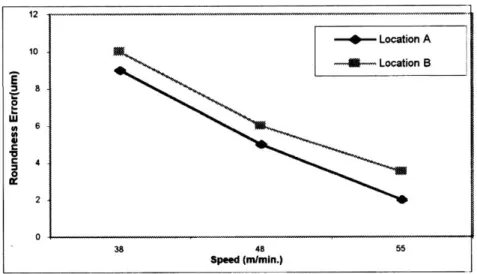
The roundness errors are plotted versus the cutting speed in Figure 8. The in- crease of cutting speed improving the roundness error of the workpiece surface.
These results can be attributed to the decrease of amplitudes of vibration at the fre- quencies that falls around the workpiece rotational speeds as shown in Figure 7, and increase of the axial cutting forces acting on the tool nose, which cause the tool to deviate. Then the perpendicular effective depth of cut will be decreased. This cause an improvement of the roundness error. Figure 9 shows also that the roundness error at location A is better than location B this is due to increasing of workpiece rigidity in location A.
The tailstock axial clamping force used in the experiments falls in the range that increases vibration level and consequently the roundness error as reported before [6]. The results in this research shows the increase of cutting speed with this force diminish the bad effect of this force on workpiece roundness error.
Figure 7: Amplitudes versus frequencies, vibration signals for locations A and B at different workpiece rotational frequencies
Figure 8: Roundness error of the turned specimens
Figure 9: Roundness error versus cutting speed
Conclusion
An analytical and experimental study has been made to examine the effect of workpiece diameter turned at different speeds on its axial vibration. Accordingly the following is concluded.
1) The workpiece axial vibration is greatly depends on workpiece dimensions during turning due to the variation of workpiece rigidity.
2) The increase of cutting speeds decreases of amplitudes of vibrations at fre- quencies that fall around the workpiece frequencies. This led to an improvement workpiece surface roundness.
3) The increase of cutting speed diminishes the effect of tailstock clamping force on the vibration amplitudes and, consequently the workpiece roundness error.
References
[1] L., C. J. and L., S. Y., "On Line Roundness error compensation via P-Integrator Learning Control", Transaction of the ASME, Vol. l14, PP 476-480, Nov.-1992.
[2] Minis I., and Tembo, A., "Experimental Verification of Stability Theory for Periodic cutting Operations". Transaction of the ASME, Vol. l15, PP 9-14, Feb. 1993.
[3] S. M. Yan and g. J. Sheu, “Vibration control of a Rotating Shaft: An Analytical solution”.
Transaction of the ASME, Vol. 66., PP 254-259, March-1999.
[4] R. G. Parker. “Analytical Vibration of Spinning Elastic, disk-Spindle System”, Transaction of the ASME. Vol. 66. PP 218–224, March-1999.
[5] Kato, H., And Nakan, G., y., “Transfer of Toundness Error from Center and Center Hole to Workpiece in Cylindrical Grinding and Its control"” anuals of CIRP, Vol. 34. PP 287-290, 1985.
[6] A. A. Ibrahim, A. M. A. Soliman, and H. A. Housin, “Influence of Workpiece Support on the Benerated Surface in turning”, Procd. Of conference Intelligent Systems in Design and Manufacturing III, Part of SPIE’S Intelligent Systems and Smart Manufactur- ing, Paper No. 4192-62, Boston, USA, Nov-2000.