T H E R M A L C O N D U C T I V I T Y D E T E R M I N A T I O N S
R T Y E
1
and A ¯ L A N G T O N
2
,
A B S T R A C T
A technique has been developed for the automatic control of a tempera
ture gradient along a guard tube surrounding a composite two-rod assembly used in thermal conductivity determinations by a longitudinal heat-flow method. Exemples are given of the performance of the system for a range of gradient ratios of the two rods.
I N T R O D U C T I O N
For many years thermal conductivity determinations on good conducting solids (λ >0.04 W c m
-1 deg. C "
1
) have been made at National Physical Laboratory using a longitudinal heatflow method [1]. The usual size of sample for this method for measurements to an accuracy of 2 per cent is a rod approximately 2.54 cm in diameter and 20 cm long. In recent times the production of some new materials has not been on a scale which enables samples of these dimensions to be made available for determinations of physical properties. The apparatus has, therefore, to be able to accommodate sample sizes from 0.3 to 3 cm in diameter and from 5 to 25 cm long and to still measure to the same order of accuracy. This fact coupled both with the large conductivity range studied and the large temperature gradients that can be involved, requires that such apparatus should be relatively simple and flexible in design. Any modifications that have to be made should be applicable to any size of sample or ther
mal conductivity value in the range.
The technique to be described is one of semi-automatic matching of temperature gradients developed on a prototype apparatus involving 2.54 cm diameter size samples for the temperature range 50°—250°C and which can be used for apparatus of the same type for samples of other sizes.
N O R M A L M E T H O D
The basic apparatus used is shown in Fig. 1 and has been described in detail elsewhere [2]. The essentials of the method are the unknown test sample with a length to
*,
2
B a s i c Physic s D i v i s i o n , N a t i o n a l P h y s i c a l Laboratory , T e d d i n g t o n , E n g l a n d .
( g )
Fig. 1. L o n g i t u d i n a l hea t f l o w a p p a r a t u s for t e m p e r a t u r e r a n g e 5 0 ° — 2 5 0 ° C.
( a ) I n s u l a t i n g base , ( b ) T e s t s p e c i m e n , ( c ) G u a r d tube , ( d ) S t a n d a r d specimen , ( e ) N i c k e l c h r o m i u m w i r e g u a r d t u b e heater , ( f ) Curren t l e a d for resistivity , ( g ) Curren t l e a d s t o heater , ( h ) P l a t i n u m w i r e s p e c i m e n heater , ( i ) N i c k e l - c h r o m i u m c o n s t a n t a n t h e r m o c o u p l e s , ( j ) I n s u l a t i n g p o w d e r , ( k ) G u a r d t u b e w a t e r c o o l i n g , (1) S p e c i m e n c o o l i n g w a t e r s u p p l i e d a t c o n s t a n t rat e an d t e m p e r a t u r e , ( m ) D i f f e r e n t i a l t h e r m o c o u p l e s
( l a g g e d w i t h c o t t o n w o o l ) .
diameter ratio of at least 8:1 joined to a similar sized reference material. The composite specimen is mounted centrally within a guard tube which has a diameter approximately three times that of the specimen and the interspace and surrounds packed with heat insulating powder. Temperature gradients are established in both and by suitable adjustment of the guard heaters the gradient in the guard is matched approximately to that in the composite specimen. At equilibrium conditions the radial heat losses are small but proportional to the out of match conditions.
The determination of thermal conductivity of a material at any particular tempe-
rature with an exact match of temperature gradients would be an exhaustive and time consuming operation. Normally it is possible to obtain two steady conditions each day but often one, and only approximate matching is attempted. The apparatus has a large heat capacity and consequently any adjustments made to one heater are reflected some considerable time later by changes in the temperature distribution elsewhere in the system. Once manual adjustments are made to the guard heaters to counterbalance a power change of the specimen heater, the system is left to attain equilibrium. By obtaining equilibrium conditions with the guard tube matched above and below the specimen it is possible to evaluate the thermal conductivity with zero radial losses. If it were possible automatically to control the matching of these temperature gradients so that a near zero equilibrium condition could be attained each time two major improvements would be obtained. There would be a saving of the time taken for a thermal conductivity determination of a particular sample and the accuracy of the determination would be improved since smaller radial corrections would need to be applied.
T H E P R O B L E M
In addition to the stability of power supplies, temperature and flow rate of the cooling water two important experimental details affect the problem of matching of temperature gradient. These are:
( 1 ) The interfacial resistance and consequent temperature discontinuity at the contact between the two specimens
Methods to reduce this involve the use of threaded joints, soldered or brazed joints or shrink fitting of collars but a step in temperature usually occurs and is difficult to match. Use of a "split" guard tube to simulate the joint in the specimen would help but this is a complicating factor since the specimens are not all of the same length.
( 2 ) The ratio of the thermal conductivities of the two rods
It is possible to keep this small and keep the gradient ratio manageable by the appropriate choice of reference material to be used for the comparative measure
ments. In some cases it would be possible to adjust the diameter ratios of the two but this is not advised if it would involve large differences in size. Guidance on the choice of reference material can be obtained by measuring the electrical resistivity of the unknown and estimating its thermal conductivity by use of the Lorenz Function [ 3 ] . However, with some materials this is not possible and the apparatus must be capable of undertaking measurements where there are large and unpredic
table conductivity ratios between the rods.
Experience had indicated that for most cases reasonable matching could be
obtained by careful use of two heaters at fixed positions on the guard tube and by adjustment of the water flow. In the first analysis it was decided not to introduce further complications by the addition of extra guard heaters but to investigate the possibility of being able to produce the matching required by the automatic regula
tion of power to the two guard heaters. Zero temperature difference between the specimen and guard would be maintained at two specific points along the length of the system and at the cold end. The two positions at which the control would be attempted would be governed to some extent by the conductivity ratios and the positions of the heaters. In general the positions would be somewhere along the top halves of the measurement sections of each rod respectively and the heaters would then be fixed immediately above these positions on the guard tube.
The main problem is to ensure that any temperature difference at either of the two points is rapidly detected and that consequent adjustment of power in the appropriate heater is at such a rate that there is no large disturbance in the overall temperature distribution. Any small changes that are produced elsewhere after some interval of time being accommodated automatically by similar adjustment of the other heater. Since any temperature measurements etc. required for the actual evaluation of thermal conductivity have to be taken at steady-state conditions the control would have to be switched off some while before such observations, to allow
these conditions to be attained. If this occurred during a small adjustment cycle ideal matching conditions may not be obtained but an overall improvement would be maintained. It must be emphasized that for each experiment the conditions will be different and that the method adopted must be flexible enough to accommodate these changes.
P R O T O T Y P E A P P A R A T U S
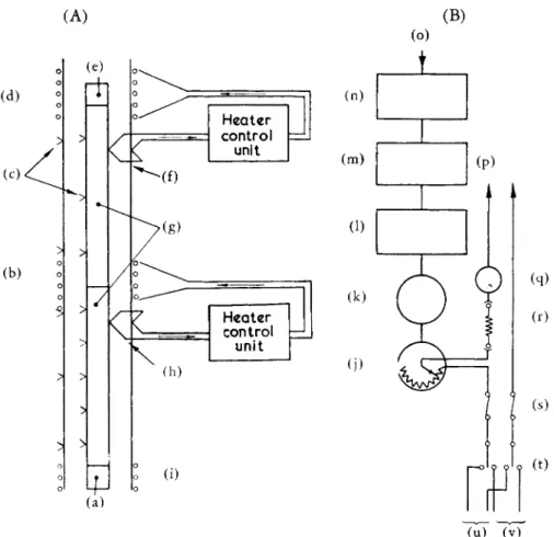
The modifications that have been made to the basic apparatus are shown schemati
cally in Fig. 2. The fixed guard heaters have been replaced by heaters insulated with silica cord which are easily adjusted in position. The control system developed for each guard heater consists of an electrically insulated thermocouple fixed in good thermal contact to the specimen and differentially connected to a similar thermo
couple fitted to the guard tube at the same height. The output from the differential thermocouple is fed to a synchronous vibrator and high gain AC amplifier (Honey
well-Brown No. 379903—7 Amplification 12 X 10°) which is coupled to a servo motor connected via a step-down gear train to the shaft of a large 200 ohm double former slate bed wire wound rheostat with large laminated phosphor bronze sliding contacts of negligible resistance.
The important individual features of the system are (1) Thermocouple attachment
It is essential that the electrically insulated individual thermocouples which form the
(`) (´) ( )
( u ) ( )
Fig. 2. S c h e m a t i c a r r a n g e m e n t for t e m p e r a t u r e g r a d i e n t control . ( A ) M o d i f i e d a p p a r a t u s , ( B ) h e a t e r c o n t r o l u n i t ,
( a ) W a t e r c o l i n g , ( b ) 2 a n d a d j u s t a b l e g u a r d heater , ( c ) M e a s u r e m e n t t h e r m o c o u p l e s , ( d ) 1st a d j u s t a b l e g u a r d heater , ( e ) S p e c i m e n heater , ( f ) 1st c o n t r o l t h e r m o c o u p l e pair , ( g ) C o m p o s i t e s p e c i m e n , ( h ) 2 n d c o n t r o l t h e r m o c o u p l e pair , ( i ) c o o l i n g , (j) G e a r trai n a n d r h e o s t a t , ( k ) M o t o r , (1) T i m e s w i t c h a n d l i m i t s w i t c h u n i t , ( m ) A . C . amplifier , ( n ) S y n c h r o n o u s vibrator , ( o ) I n p u t , ( p ) T o g u a r d heater , ( q ) D u a l r a n g e ˇ I A m p . , ˇ 5 A m p . , ( r ) H e a t e r serie s resistor , ( s ) F u s e s , ( t ) C h a n g e o v e r / o f f
s w i t c h , ( u ) I I O V stabilised , ( v ) I I O V battery .
differential couple and supply the control signal should reproduce the temperature of specimen and guard at the points of attachment. Several methods of insulating and attaching the thermocouples were developed.
(i) The small bead of the 40 swg nickel-chromium/constantan thermocouple is sandwiched between two very thin wafers of mica and clamped into position with a thin metal band. Alternatively the bead is spot welded to the inner surface of the retaining band which is then clamped into position over a thin wafer ring of mica.
(ii) The bead is coated with a thin film of insulating ceramic cement and attached with a further thin film of the non conducting cement.
(iii) The bead is fitted tightly into a 1 mm length of alumina insulating tube
0.4 mm Ο. D. which is wedged into a hole drilled in the specimen or guard tube.
This method although successful is not advised for small samples since holes additio
nal to those already present for measurement purposes would affect the cross sectional area and could affect the heat flow in the specimen.
(2) Thermocouple sensitivity and drive response
The emf of the thermocouples used is approximately 40 μν/°€. With the amplifier and motor chosen, drive could be obtained for an input of less than 5 μν. It was possible to obtain power adjustment for a temperature difference of rather over 0.1°C
( 3 ) Power adjustment
From experience of the behaviour of the apparatus together with the few limited calculations that could be made for some of the unknown quantities involved a 200:1 reduction gear ratio unit is coupled between the motor and rheostat. An alternative 100:1 ratio is combined into the unit with a simple change over lever. This is incorporated for possible application when the apparatus is used for smaller samples when the attainment of equilibrium should be accomplished more rapidly due to the lower heat capacity of such an assembly. With the motor (22 rpm) and rheostats used, changes of resistance of less than 0.5 (1-0) ohms per minute at constant motor speed are obtained. In addition, since the motor speed is linearly related to the input voltage up to approximately 150 μν there is a consequent reduction of this rate of change of resistance as the temperature difference decreases. Each control unit is rendered failsafe to drive to maximum resistance in the event of any failure in the thermocouple circuit.
E X P E R I M E N T A L R E S U L T S
A preliminary experiment with one unit only was undertaken to investigate whether close temperature matching at two opposite points could be maintained. From records taken it was found that at equilibrium (1 1/2 h after control switched off) the temperature difference was at worst 0.5 °C when the mean temperature was 100°C and 5"C when the mean temperature was 500°C and it was inside these values before the control was switched off. This indicated that there was the expected slight drift due to the small fluctuations that did occur in system response, power, water flow etc. In addition there was very good agreement between the temperatures indicated by the individual thermocouples of the control thermocouple and those attached directly to the specimen and guard.
Full scale experiments were then carried out on determinations of thermal conductivity of 1" diameter samples of unknown materials using control units fitted
to both guard heaters together with manual control of water flow at the base of the specimen and guard tube. Several conductivity ratios were chosen to investigate the behaviour of the system to the different gradients that would ensue. In each case the readings from measurement thermocouples attached directly to the specimen and guard tube at approximately identical positions to the control couples were monitored to study the time of response and if there was any significant thermal oscillation.
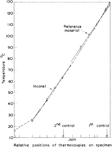
Examples of typical temperature distributions obtained at equilibrium conditions for three individual experiments involving materials giving a range of thermal conductivity ratios are shown in Figs. 3—5.
Fig. 3 relates to a sample of Inconel 702 when screwed to a reference material of
I 3 0
I 2 0
N O
I O O
9 0
8 0
R e f e r e n c e
m a t e r i a l \ /Γ
I
st
c o n t r o l
ι ι ι iL
J o i n
R e l a t i v e p o s i t i o n s o f t h e r m o c o u p l e s o n specimen a n d g u a r d t u b e .
Fig. 3. T y p i c a l t e m p e r a t u r e d i s t r i b u t i o n for i n c o n e l s p e c i m e n . Q , S p e c i m e n c o u p l e s , X, G u a r d t u b e c o u p l e s .
2 c m
high alloy steel [4]. The conductivity ratio in this case is approximately 1:1. The curve shows the very good type of matching which can be obtained in this case.
The particular curve is that obtained as the result of adjusting the power in the specimen heater with the top section maintained at approximately 500°C at 17.30 h one day, and allowing the control to take effect until 0700 h the following day, the measurements indicating the position at 0900 h the same day. This type of matching using manual control would probably take a further day or so. It was found in the experiment that individual temperatures could be controlled to better than 1 per cefit of the actual temperature and the overall match conditions were better than 1°C at 100°C and 5°C at 4 5 0 ° C
Fig. 4 shows one distribution obtained during the experiment on a sample of
5 0 0 , • ,
C o l l a r
R e l a t i v e p o s i t i o n s o f t h e r m o c o u p l e s on specimen and guard t u b e .
Fig. 4. T y p i c a l t e m p e r a t u r e d i s t r i b u t i o n for t i t a n i u m carbid e s p e c i m e n . 0 , S p e c i m e n c o u p l e s , X , G u a r d t u b e c o u p l e s .
2 c m
titanium carbide in a shrunk fit collar screwed to a sample of Armco iron as re
ference material [5]. The conductivity ratio of these materials is approximately 1:2.5 reducing to 1:2 over the temperature range studied. Once again the system coped adequately this time with a difference in gradients. With the higher thermal conductivities of these two materials and the corresponding increase in heat flow the actual percentage radial corrections that had to be applied to the measured energies were in many cases less than those for the previous example.
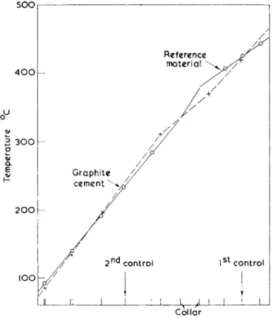
The example indicated in Fig. 5 is for a sample of a graphite cement for which,
3 0 0
o f c o l l a r c o l l a r
R e l a t i v e p o s i t i o n s o f t h e r m o c o u p l e s o n s p e c i m e n a n d g u a r d t u b e .
Fig. 3. T y p i c a l t e m p e r a t u r e d i s t r i b u t i o n for g r a p h i t e c e m e n t s p e c i m e n . ( • ) , S p e c i m e n c o u p l e s , X , G u a r d t u b e c o u p l e s .
I I
2 c m
until the measurements were undertaken, no good estimate of thermal conductivity could be made. From the results of the experiment with the rod soft-soldered in a collar and screwed to the same rod of Armco iron as used previously it was found that the thermal conductivity ratio was 1:4 decreasing with increase of temperature to 1:3. The control was not as good as in the case of the titanium carbide but was much better than that obtained from the early settings when no automatic control was used. However, even with this high conductivity ratio the gradients were adequately matched and a situation was produced in the "collar" region whereby the
heat lost from the specimen above the join was counterbalanced by that gained by the specimen below the join thus producing very small radial corrections.
C O N C L U S I O N S
The matching of temperature gradients in a longitudinal heat-flow method for measurement of thermal conductivity of good conducting solids has been accom
plished semi-automatically. A simple method involving two guard heaters each controlled by a motor driven rheostat activated by the amplified signal from a differential input from thermocouples attached at identical heights on specimen and guard tube has been used successfully to obtain adequate practical matching of gradients for a wide range of gradient ratios. The method appears to overcome dangers of oscillation and drift by the use of very slow power adjustment to the heaters and stable non-drift amplifiers and power supplies. In determinations of thermal conductivity the improvement of the matching obtained has reduced the radial corrections and yielded more reliable results. The time intervals for producing good matched conditions between one fixed temperature and another have been reduced. The technique can be applied without modifiation to the method for any particular size of sample.
Improvements and refinements of the technique are still under investigation and the next step will be to attempt to control the matching of temperature gradients in the high temperature version of this method in which no direct water cooling is employed and w
T
here noble metal thermocouples with an output of approximately 10 μν/°€ are used.
T h e a u t h o r s w i s h t o a c k n o w l e d g e th e e n c o u r a g e m e n t a n d h e l p g i v e n t o t h i s i n v e s t i g a t i o n b y D r . R . W . P o w e l l of t h e B a s i c P h y s i c s D i v i s i o n . T h e y furthe r w i s h t o a c k n o w l e d g e th e assistanc e of M r . F . H . S a r g e a n t of W e s t D e s i g n O f f i c e w h o d e s i g n e d th e fina l gea r s y s t e m u s e d . T h e w o r k h a s b e e n carrie d o u t a s par t o f t h e g e n e r a l researc h p r o g r a m m e of th e B a s i c P h y s i c s D i v i s i o n of t h e N a t i o n a l P s y s i c a l Laboratory . T h e p a p e r is p u b l i s h e d w i t h th e a p p r o v a l of th e D i r e c t o r of t h e Laboratory .
R E F E R E N C E S
1. P o w e l l , R W , Proc. Phys. Soc. 48 ( 1 9 3 6 ) 3 8 1 .
2. P o w e l l , R W a n d T y e , R P , The Engineer 209 ( I 9 6 0 ) 7 2 9 . 3. P o w e l l , R W , I n c o u r s e o f p u b l i c a t i o n .
4. P o w e l l , R W an d T y e , R P , Brit. J. Appl. Phys. 11 ( I 9 6 0 ) 1 9 5 .
5. P o w e l l , R W , H i c k m a n , M J , T y e , R a n d W o o d m a n , M J , P r o g r e s s in I n t e r n a t i o n a l R e s e a r c h o n T h e r m o d y n a m i c an d T r a n s p o r t Properties , p . 4 6 6 . A m e r i c a n Societ y of M e c h a n i c a l E n g i n e e r s , 1 9 6 2 .