Coatings 2020, 10, 205; doi:10.3390/coatings10030205 www.mdpi.com/journal/coatings
Article
Micropillar Compression Study on the Deformation Behavior of Electrodeposited Ni–Mo Films
Jenő Gubicza 1,*, Garima Kapoor 1, Dávid Ugi 1, László Péter 2, János L. Lábár 1,3 and György Radnóczi 3
1 Department of Materials Physics, Eötvös Loránd University, P.O.B.32, H-1518 Budapest, Hungary;
garima_kpr_91@yahoo.com (G.K.); ugdtaat@caesar.elte.hu (D.U.); labar.janos@energia.mta.hu (J.L.L.)
2 Wigner Research Centre for Physics, Hungarian Academy of Sciences, Konkoly-Thege út 29-33, H-1121 Budapest, Hungary; peter.laszlo@wigner.mta.hu
3 Institute for Technical Physics and Materials Science, Centre for Energy Research, Hungarian Academy of Sciences, Konkoly-Thege út 29-33, H-1121 Budapest, Hungary; radnoczi.gyorgy@energia.mta.hu
* Correspondence: jeno.gubicza@ttk.elte.hu; Tel.: +36-1-3722876
Received: 26 January 2020; Accepted: 25 February 2020; Published: 27 February 2020
Abstract: The influence of Mo addition on the compression behavior of Ni films was studied by micropillar deformation tests. Thus, films with low (0.4 at.%) and high (5.3 at.%) Mo contents were processed by electrodeposition and tested by micropillar compression up to the plastic strain of about 0.26. The microstructures of the films before and after compression were studied by transmission electron microscopy. It was found that the as-deposited sample with high Mo concentration has a much lower grain size (~26 nm) than that for the layer with low Mo content (~240 nm). In addition, the density of lattice defects such as dislocations and twin faults was considerably higher for the specimen containing a larger amount of Mo. These differences resulted in a four-times higher yield strength for the latter sample. The Ni film with low Mo concentration showed a normal strain hardening while the sample having high Mo content exhibited a continuous softening after a short hardening period. The strain softening was attributed to detwinning during deformation.
Keywords: Ni–Mo films; micropillar compression; strain-softening; twins; detwinning
1. Introduction
Alloying with Mo is an effective way to tailor the physical properties of Ni. For instance, the Curie temperature decreases significantly with increasing Mo concentration in Ni [1]. For pure Ni, the temperature of transition from ferromagnetic to paramagnetic state is 354 °C which is reduced to about 60 °C when the Mo concentration increases to about 5 at.% [1]. On the other hand, the hardness and the wear resistance of Ni considerably increase with the addition of Mo, therefore Ni–Mo alloys are often used as hard coatings [2]. The improvement of hardness and wear resistance with grain refinement is a general phenomenon for Ni-based coatings, be achieved either with alloying or with incorporation of ceramic particles [3]. Alloying may result not only in the decrease of the grain size but also in the increase of the lattice defect density [4]. It has been shown that Mo addition enhances the density of twin faults [4] which improves the hardness since twin faults are obstacles against dislocation motion similar to grain boundaries [5]. In the case of alloying, the chemical nature of the added element also affects the mechanical properties, and this is why tungsten is a common candidate besides molybdenum for alloying nickel [6]. In dispersion-hardened coatings, the primary hardening factor is the grain refinement as a result of the particle incorporation, regardless of the properties of the particles incorporated [3].
As with their physical behaviour, Ni–Mo alloys also obtained attention due to their chemical properties. Ni–Mo is applied as a catalyst in hydrogen production either in the form of coating or powder since this material shows a high activity and a long-term stability in this process [7–9]. In bulk form, Ni–Mo is used as a substrate for epitaxially grown superconducting coatings as the sharp cube texture formed after rolling and subsequent annealing in Ni–Mo alloys is beneficial for the layer deposition [10]. Thus, Ni–Mo alloys have drawn significant attention from the scientific community due to their important applications in either bulk, powder or thin layer form.
Ni–Mo electroplated films can be produced by codeposition of Ni and Mo [11,12]. This is a typical induced codeposition process which means that the incorporation of Mo in the layer is induced by the deposition of Ni, i.e., pure Mo cannot be obtained by electroplating. The conditions of electrodeposition, such as bath composition, pH value, current density and stirring, influence strongly the concentration of the deposited Mo [13–15]. It was shown that the Mo content can reach 74 at.% in electrodeposited Ni films, but in this case the current efficiency became extremely low (about 1%) [15,16]. It has also been revealed that appropriate additives may facilitate the deposition of Mo in Ni [17].
Former studies revealed that the Mo content significantly influences the microstructure and hardness of Ni electrodeposits [4,18]. Namely, the grain size decreased while the density of lattice defects (e.g., dislocations and twin faults) increased with increasing Mo concentration. As a consequence, the hardness of the layers was considerably enhanced with the addition of Mo [18,19].
For instance, the hardness of a pure nanocrystalline Ni film was found to be about 4.3 GPa which increased to 5.5–6.0 GPa when 3–13 at.% Mo was codeposited with Ni [20]. It is noted that this hardness can be further enhanced with the application of annealing at 400–550 °C for 1 h [20,21]. This effect is referred to as anneal-hardening and may cause an increase of the hardness with a factor of two for electrodeposited Ni–Mo films. This hardening was explained by the segregation of Mo solutes to Ni grain boundaries which impeded both dislocation emission from grain boundaries and the grain boundary sliding during straining. Although the hardness of Ni–Mo films was studied extensively, the stress-strain response for these materials has not been studied yet.
In this paper, the deformation behavior of electrodeposited Ni–Mo films with lower (0.4 at.%) and higher (5.3 at.%) Mo contents was investigated by micropillar compression. This test has already been applied to the study of the mechanical properties of Ni, Ni-W and Ni-ceramic composite films [22–25]. At the same time, to the knowledge of the authors, this is the first micropillar compression on Ni–Mo films. It will be shown that not only the yield strength but also the strain-hardening behavior exhibits significant differences in the two layers. For the explanation of the different mechanical performances of the Ni films with low and high Mo contents, a detailed characterization of the microstructure was conducted before and after compression.
2. Materials and Methods
2.1. Film-Processing by Electrodeposition
Ni–Mo films were processed by electrodeposition at room temperature (RT) using a solution containing 0.52 mol/liter NiSO4, 0.26 mol/liter sodium citrate, 0.1 g/liter sodium dodecylsulfate as wetting agent, and Na2MoO4 in varying concentration up to 6 mmol/liter. To minimize the impurity content of the films, a high-purity nickel sulfate salt with a Co concentration lower than 50 ppm was applied in the electroplating process. The pH of the bath was set as 6.1 ± 0.08 since this value yielded a very high Ni deposition efficiency (about 98%) [26]. Although saccharin is known as an efficient stress reliever for the deposition, it was not applied because the resulting sulfur content in the deposits may also impact the mechanical properties of the films. The current density was selected as
−5.6 mA/cm−2. This current density was about one order of magnitude lower than the values used commonly for the production of Ni–Mo films. The low current density yielded similarly high efficiency of deposition (96%–98%) as obtained for pure Ni. Then, the Mo content in the films was tailored by changing the Mo concentration in the bath. Two films were deposited with low (0.4 ± 0.1 at.%) and high (5.3 ± 0.4 at.%) Mo contents. These values were determined by energy-dispersive X-
ray spectroscopy (EDS) in an FEI Quanta 3D scanning electron microscope (SEM, Thermo Fisher Scientific, Waltham, MA, USA). The electrodeposited samples with low and high Mo contents are denoted as LMo and HMo, respectively.
The deposition of the Ni–Mo films was carried out on a Cu substrate. First, the substrate was degreased and then placed horizontally at the bottom of the cell. A nickel wire spiral served as the counter electrode which was immersed into a frit-separated chamber of the cell in order to avoid the contamination of the deposit with the disintegrated grains of the anode. The deposition was stopped when the desired film thickness (about 20 µm) was achieved.
2.2. Microstructure Characterization of the As-Grown Film by Transmission Electron Microscopy
Transmission electron microscopy (TEM) was used for the determination of the average grain size in the as-deposited Ni–Mo films. The TEM samples were thinned by ion milling using liquid nitrogen cooling in order to avoid undesired annealing during thinning. In this procedure, GATAN G1 low temperature glue was used at 60 °C for fixing the sample in a Ti disk with a diameter of 3 mm.
Then, the specimen was milled by Ar ions with the energy of 7 keV until perforation. The TEM experiments were carried out by a Philips CM20 electron microscope (Philips, Amsterdam, The Netherlands) operating at 200 keV. The mean grain size was determined as the average of the diameters of the grains identified in dark-field TEM images. About twenty grains were evaluated in this way for each film.
2.3. Characterization of the Crystallographic Texture of the Ni–Mo Films
The crystallographic texture of the films was characterized by the analysis of X-ray diffraction (XRD) pole figures which were measured by a Smartlab diffractometer made by Rigaku company, Japan using parallel-beam optics and Cu Kα radiation with the wavelength of 0.15418 nm. Before the pole figure measurements, diffraction patterns were taken by the Smartlab diffractometer using Bragg-Brentano geometry. The diffraction angles for reflections 111, 200 and 220 were determined for both Ni–Mo layers and these 2θ values were used in the pole figure measurements.
2.4. Micropillar Compression Test
The deformation behavior of the Ni–Mo films was studied by micropillar compression.
Micropillars with square cross sections were fabricated by a focused ion beam (FIB) in the same SEM microscope as used in EDS experiments (see Section 2.1). The edge and the height of the pillars were 3 and 6 µm, respectively. The compression experiments were carried out by a home-made indenter device using a flat-ended cylindrical punch. The precision of the indentation depth and the load were
~1 nm and ~1 µN, respectively. In the present experiments, the maximum applied load was ~15 mN. The technical details of the indenter device can be found in reference [27]. To ensure the reproducibility of the compression data, three micropillars were fabricated and compressed for each film. SEM images were also taken on the pillars before and after deformation.
2.5. Characterization of the Microstructure of the Micropillars before and after Compression
The microstructure of the pillars before and after compression was studied by TEM and high- resolution TEM (HRTEM). First, thin sections parallel to the longitudinal axis of the pillars were cut using the FIB technique. Then, these foils were thinned by ion milling until perforation using Ar ions.
The HRTEM structural characterization of the samples was carried out by a FEI Titan-Themis transmission electron microscope with a Cs corrected objective lens (point resolution is around 0.09 nm in HRTEM mode) operated at 200 kV.
3. Results
3.1. Microstructure of the As-Deposited Ni Films with Low and High Mo Contents
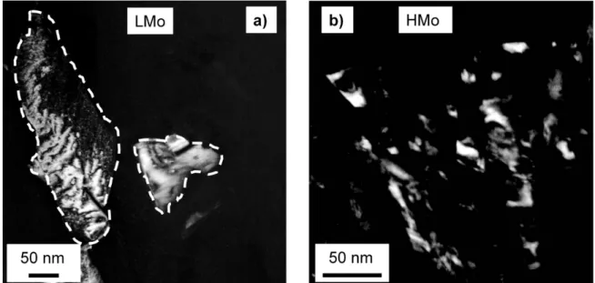
Figure 1 shows dark-field TEM images taken on the films LMo and HMo (lateral view). The average grain sizes determined from TEM images are ~240 and ~26 nm for samples LMo and HMo, respectively. Figure 1a also reveals that the large grains bordered by white dashed curves contain subgrains in the LMo film, appearing as bright and dark regions inside the grains. The size of these subgrains varies between 20 and 50 nm which is in good agreement with the diffraction domain size determined formerly by X-ray line profile analysis (XLPA) [4]. Namely, the average diffraction domain size was obtained as ~40 nm from fitting the experimental X-ray diffractogram using a theoretical pattern calculated for the description of the diffraction peak broadening caused by the ultrafine-grained microstructure [4]. For sample HMo, the X-ray diffraction domain size was ~47 nm which is slightly higher than the grain size determined by TEM. This difference can be explained by the many orders of magnitude larger volume studied by XLPA as compared to TEM. Nevertheless, the similar grain and diffraction domain sizes for layer HMo indicate that for this film the grains were not divided into subgrains.
Figure 1. Dark-field transmission electron microscope (TEM) micrographs showing the grains in films with (a) low Mo content (LMo) and (b) high Mo content (HMo). In (a) the grains are bordered by white dashed curves for a better visibility.
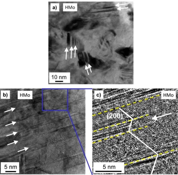
The TEM image in Figure 2a shows that the nanograins in sample HMo contain twin faults.
Former XLPA investigation revealed that the twin fault probability in layer HMo is as high as ~3.9%
which corresponds to an average twin fault spacing of ~5 nm. This value is in accordance with the visual impression obtained from the HRTEM image in Figure 2b where some twin faults are indicated by white arrows. A magnified part of this HRTEM picture is Fourier-filtered in Figure 2c. In this image, only the (200) lattice fringes are shown. The yellow dashed lines indicate twin faults. The white arrow in Figure 2c marks the end of a twin lamella in the grain interior which usually comprises partial dislocations [28]. Sample LMo does not contain significant amount of twin faults as suggested by both TEM and XLPA since the twin fault probability determined by the latter method was under the detection limit (˂0.1%) [4].
Figure 2. Bright-field TEM micrograph (a) and high-resolution TEM (HRTEM) image (b) taken on sample HMo. The white arrows indicate some twin faults. (c) shows a magnified and Fourier-filtered part of (b) (indicated by the blue frame). The dashed yellow lines mark twin faults. The white arrow in (c) indicates a twin lamella ending in the grain interior.
The crystallographic textures for samples LMo and HMo are characterized by the 111, 200 and 220 pole figures shown in Figure 3. The normal vector of the film surface is perpendicular to the plane of the pole figures. It is evident that the LMo film has a strong 200 texture parallel to the film normal.
For sample HMo, no preferred orientation was detected.
Figure 3. Pole figures for orientations 111, 200 and 220 as obtained by X-ray diffraction (XRD) for samples LMo and HMo. The normal vector of the film surface is perpendicular to the plane of the pole figures.
3.2. Compression Behavior of the Micropillars Fabricated from the Ni–Mo Films
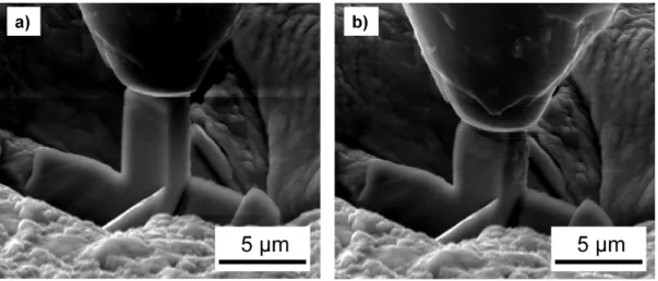
As an example, Figure 4a,b show a micropillar fabricated from the film LMo before and after compression. The engineering stress versus plastic strain curves for samples LMo and HMo are plotted in Figure 5a,b, respectively. Very similar curves were obtained for other pillars manufactured from the same film. The engineering stress was obtained as the ratio of the applied force and the initial cross section of the pillars. The plastic portion of the engineering strain was calculated as follows. First, the engineering strain was determined as the ratio of the displacement and the initial pillar height (6 µm). Then, the elastic part of the strain was calculated as the ratio of the engineering stress and the elastic modulus. The latter quantity was determined as the slope of the initial linear part of the engineering stress-strain curve. Finally, the plastic strain was calculated as the difference between the total engineering strain and the elastic strain.
Figure 4. A micropillar under the indenter before (a) and after (b) compression for the film LMo.
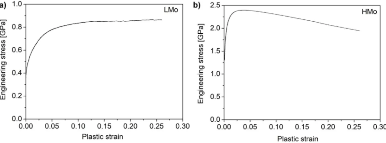
Figure 5. Engineering stress versus plastic strain obtained by micropillar compression for the films LMo (a) and HMo (b).
The yield strength values for samples LMo and HMo were obtained as 0.35 ± 0.05 and 1.3 ± 0.2 GPa, respectively. The sample LMo showed a monotonous hardening while the film HMo exhibited a strain-softening after an initial hardening stage. The maximum compressive stress values were 0.86 and 2.4 GPa for specimens LMo and HMo, respectively. These stresses were achieved at the plastic strains of 0.26 (at the end of the test) and 0.04 for the films LMo and HMo, respectively. The stress- strain behavior of sample LMo is not surprising; however, the strain-softening for film HMo is unusual. Therefore, the reason of this softening for sample HMo was studied by comparing the microstructures before and after micropillar deformation. These results are presented in the next section.
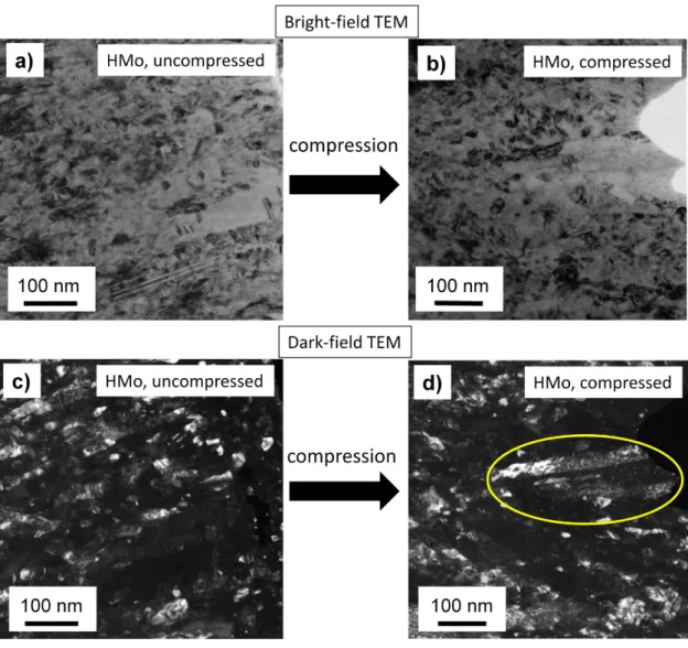
3.3. Changes of the Microstructure in the Ni Film with High Mo Content during Micropillar Compression A TEM study was conducted on the microstructures of uncompressed and compressed micropillars manufactured from the film HMo. Figure 6 shows illustrative examples for the bright- field and the corresponding dark-field TEM images obtained before and after compression up to the plastic strain of 0.26. The average grain size determined from the images was about 24 nm for both the uncompressed and compressed micropillars, i.e., it remained unchanged during deformation.
This value is practically the same as the grain size (~26 nm) obtained from the TEM images taken on the as-processed film HMo. It should be noted, however, that some larger grains with the size of about 100–200 nm were also found both before and after compression. As an example, a large grain in the compressed pillar is marked by a yellow ellipse in Figure 6d. This grain contains twin lamellas as revealed by the dark-field image in Figure 6d. It is noted that large grains were also observed in the uncompressed pillars. The numbers and the diameters of these grains were similar before and after compression. For example, long twin lamellas in a large grain can be seen at the bottom of Figure 6a taken on an uncompressed pillar. These large grains were formed in the nanocrystalline matrix during deposition and micropillar compression did not yield either their fragmentation or growth due to the relatively low plastic strain (about 0.26).
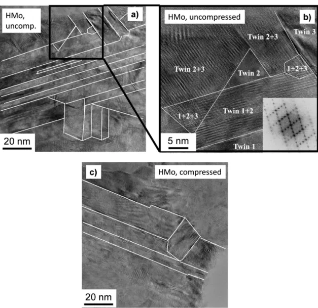
The HRTEM images in Figure 7 show a high density of twin faults in both the uncompressed and compressed pillars for film HMo. The crystallographic direction <110> is lying perpendicular to the images. The twin boundaries are marked by white lines. Comparing Figure 7a,c, it seems that the twin fault density is lower for the compressed pillar than that in the undeformed state. Figure 7b shows a magnified part of Figure 7a. In this picture, bright and dark lattice fringes are visible parallel to the {111} planes and the periodicity of these fringes is three times larger than the lattice spacing for planes {111}. The Fourier transform of this HRTEM image can be seen in the lower right corner of Figure 7b which reveals that beside the fundamental fcc diffraction points additional spots appeared on the <111> lines of the reciprocal lattice, dividing the spacing between the fcc reciprocal lattice points into three. A former study explained these extra diffraction points by single and double
diffraction from twins [29]. The different twin variants are indicated by numbers in Figure 7b. In some areas of Figure 7b, more than one twin variant exists overlapping each other in the TEM foil, which resulted in double diffraction of electrons.
Figure 6. Bright-field (a,b) and the corresponding dark-field (c,d) TEM images taken on uncompressed (a,c) and compressed (b,d) micropillars for sample HMo.
4. Discussion
The film HMo exhibited a much higher yield strength (~1.3 GPa) than that measured for sample LMo (~0.35 GPa). This difference can be explained by the combined hardening effect of the smaller grain size and the higher lattice defect (e.g., twin fault) density for the specimen HMo. Indeed, twin faults are similarly effective obstacles against dislocation motion such as the general grain boundaries [30,31]. Since the twin fault spacing in film HMo (about 5 nm) is smaller than the grain size (about 26 nm), the former value must be considered as the average distance between the dislocation glide obstacles.
For sample LMo, either the grain size (~240 nm) or the crystallite size (~40 nm) is selected for the average obstacle spacing, it is much higher than the value determined for the film HMo, resulting in a softer yielding. In addition to the smaller obstacle spacing, the higher solute hardening for sample HMo may also contribute to the enhanced yield strength. Moreover, the different crystallographic textures in samples LMo and HMo also increased the difference between the yield strength values.
Namely, film LMo exhibited a strong 200 texture and according to the Taylor model the Taylor factor for compression along direction <200> is about 2.4 which is lower than the value for an untextured fcc material (~3.06) [32]. The film HMo has no considerable texture (see Figure 3), therefore the Taylor
factor for this material is surely higher than that for sample LMo during micropillar compression parallel to the film normal.
Figure 7. HRTEM images taken on uncompressed (a,b) and compressed (c) micropillars for the film HMo. The white lines indicate twin faults. (b) is a magnified part of (a) marked by the black frame.
The diffraction pattern in (b) is obtained as the Fourier transform of the corresponding HRTEM image.
Figure 5 reveals that not only the yield strength but also the stress–strain behavior of the films LMo and HMo differ significantly. Namely, sample LMo exhibited strain hardening in the entire range of strain (up the strain of 0.26) while for film HMo softening was observed for the strains higher than ~0.04. Theoretically, softening can be caused by grain growth during plastic deformation.
Indeed, former studies have shown that the high-pressure torsion (HPT) technique applied up to 30 turns on electrodeposited Ni–20% Fe caused an increase of the grain size from ~20 to ~50 nm at the equivalent strain of about 200 [33] and to ~115 nm when the equivalent strain increased to ~1300 [34].
This grain growth may be caused by a dynamic recrystallization of the as-deposited microstructure during deformation due to the high driving force owing to the large defect density and the small grain size. However, in sample HMo considerable grain growth did not occur during deformation, which can be attributed to the relatively low applied strain. Therefore, this effect is ruled out in the explanation of the softening observed for layer HMo.
The as-processed sample HMo contains a very high amount of grown-in twin faults, and detwinning during pillar compression might have occurred that could cause the observed softening.
Detwinning is a result of the interaction between twin boundaries and gliding dislocations, yielding
thinning or full disappearance of twin lamellae [35]. In the first step of detwinning, a gliding dislocation at the twin boundary dissociates into two partials. For a material with high stacking fault energy (SFE), these partials are sessile Shockley and glissile Frank dislocations [36]. The Shockley partial slips along the twin boundary, resulting in a thinning of the twin lamella with one {111} plane.
This Shockley partial in the twin boundary is also called as twinning partial and it can also form if a dislocation is transmitted into the adjacent twin lamella [37]. The collective slip of twinning partials on successive glide planes parallel to the twin boundary can lead to a complete disappearance of a twinned region [28]. This effect has already been observed in electrodeposited Ni–20% Fe film processed by HPT [38]. Ni alloys have high SFE, therefore twinning is not a preferred mechanism of plastic deformation. At the same time, during the deposition of nanocrystalline pure Ni and Ni alloys many grown-in twin faults form as these have the lowest energy among the grain boundaries. Above the grain size of 20 nm, dislocation glide is an important deformation mechanism in Ni alloys [38], and therefore the interaction between moving dislocations and grown-in twin boundaries may cause detwinning. Then, the gradually decreasing twin fault density can result in a continuous softening during deformation as shown in Figure 5b. Indeed, the amount of twin faults in the film HMo seems to decrease during the present micropillar compression tests as suggested by the comparison of Figure 7a,c. The twin faults disappeared by detwinning were not replaced by new ones during compression as the probability of deformation twinning is very low in both studied Ni–Mo alloys as revealed in our former studies where the same compositions were deformed by HPT [39]. Up to the strain of about 1000, considerable twinning was not observed in bulk Ni samples with either ~0.3 or
~5 at.% of Mo. It should be noted that the reduction of the twin fault density during pillar compression of the film HMo is difficult to determine with good statistics from Figure 7 due to the small studied area (about 100 nm × 100 nm). However, the HRTEM images in Figure 7 suggest that in the investigated area the twin fault density decreased to about half during deformation.
Considerable reduction of grown-in lattice defects (e.g., dislocations and twin faults) during deformation of nanocrystalline fcc metals processed by bottom-up methods has already been observed in former studies [40]. This is a deformation-induced relaxation of nanostructures with extremely high density of growth defects. Due to the very small grain size and the extremely high defect density, nanocrystalline metals processed by bottom-up methods are very far from the equilibrium. However, this state can be frozen in the material as the annihilation of defects is strongly hindered kinetically by the impurities and the alloying elements. At the same time, plastic deformation of the as-processed samples causes a mechanical perturbation which can result in a shift of the material to a more equilibrium state by the annihilation of a portion of grown-in defects. For instance, a Ni–18 wt.% Fe alloy processed by pulsed electrodeposition was subjected to rolling at RT and liquid nitrogen temperature (LNT) up to the true strains between 0.4 and 0.6 [41]. This deformation resulted in a decrease of the twin fault probability from about 3.2% to 1.5%–2.2%. In addition, the initial dislocation density was also reduced from 370 × 1014 m−2 to (180–220) × 1014 m−2 as revealed by XLPA. During plastic deformation of nanomaterials with the grain sizes higher than 10–
20 nm, dislocations are emitted from the grain boundaries which slip across the host grain and are absorbed by the boundary at the opposite side of the grain. The interaction between the plasticity- induced and the growth dislocations can lead to their annihilation. The decrease of lattice defect density can result in softening of nanomaterials processed by bottom-up methods, as in the case of film HMo in the present study. It should be noted that softening in highly twinned microstructures was also observed for other fcc metals, such as Cu [42,43]. For copper, detwinning was detected not only during plastic deformation of nanotwinned films [43] but also for powders nanostructured by preliminary milling [44].
It is worth noting that during plastic deformation both defect formation and annihilation occur simultaneously and at high strains (>1) there is a dynamic equilibrium between these processes, resulting in a saturation of the values of the densities of lattice defects (e.g., dislocation and twin faults) [45]. If the density of grown-in defects in nanomaterials processed by bottom-up methods is higher than the saturation value achievable by severe plastic deformation, then deformation most probably results in a reduction of defect density. This was the case for sample HMo where the
dislocation density in the electrodeposited film (~114 × 1014 m−2) was much higher than the saturation value of ~60 × 1014 m−2 measured by XLPA on a sample processed from a coarse-grained material by HPT [39]. In addition, a high twin fault probability was detected in film HMo (~3.9%) while significant twin fault probability was not found in the sample processed till saturation by HPT.
Therefore, defect density reduction was expected for layer HMo during micropillar compression. At the same time, in film LMo the density of growth dislocations was slightly lower (~23 × 1014 m−2) than the saturation value achieved by HPT (~30 × 1014 m−2). In addition, twins were not observed in either the electrodeposited or the HPT-processed LMo samples [39]. Thus, defect formation and a corresponding hardening were expected in this case which is in accordance with the present experimental observation. This research can be continued by studying the transition from strain hardening to softening as a function of Mo concentration in nanocrystalline Ni deposits.
5. Conclusions
The deformation behaviors of nanocrystalline Ni films deposited with low and high Mo contents were studied by micropillar compression test which was performed up to the plastic strain of 0.26.
The following conclusions were drawn from the results:
• The film with high (5.3 at.%) Mo concentration had a much larger yield strength (1.3 GPa) than the value obtained for low (0.4 at.%) Mo content (0.35 GPa). This difference can be attributed to the higher solute hardening, the much smaller grain size and the higher defect density in the former sample. In film HMo, nanotwins with an average spacing of ~5 nm were formed while considerable twinning was not observed in specimen LMo. In addition, a strong 200 texture was observed for film LMo while no considerable texture was detected in sample HMo, and this change also contributed to the higher yield strength of the latter specimen.
• The Ni film with low Mo concentration exhibited strain-hardening in the studied strain range, yielding a maximum compressive stress of 0.86 GPa. At the same time, layer HMo showed a fast hardening to the stress of 2.4 GPa which was followed by a continous softening between the strains of 0.04 and 0.26.
• The strain-softening for film HMo cannot be explained by grain coarsening since the average grain size remained about 26 nm during compression. On the other hand, a decrease of the twin density during compression was observed by comparing the TEM images taken on the pillars before and after deformation. This detwinning process caused the observed softening.
Author Contributions: conceptualization, J.G.; methodology, L.P., J.L.L., G.R. and D.U.; formal analysis, G.K.
and G.R.; investigation, G.K., J.L.L, G.R. and D.U.; resources, J.G., L.P., J.L.L and G.R.; writing—original draft preparation, J.G.; writing—review and editing, G.K., D.U., L.P., J.L.L and G.R.; visualization, J.G. and G.K.;
supervision, J.G.; funding acquisition, J.G, L.P., J.L.L and G.R. All authors have read and agreed to the published version of the manuscript.
Funding: This work was financed partly by the Ministry of Human Capacities of Hungary within the ELTE University Excellence program (1783-3/2018/FEKUTSRAT). This research was also funded by the Hungarian National Research, Development and Innovation Office through the OTKA NN112156 project. The VEKOP- 2.3.3-15-2016-0000 project of the European Structural and Investment Funds is also acknowledged. This research was funded partly by EFOP-3.6.1-16-2016-00018 project: “Improving the role of research+development+innovation in the higher education through institutional developments assisting intelligent specialization in Sopron and Szombathely”. The work was performed in the frame of Széchenyi 2020 program: “Innovative processing technologies, applications of energy engineering and implementation of wide range techniques for microstructure investigation”.
Acknowledgments: The authors acknowledge the help of Mrs. Éva Fekete in processing of the electrodeposited Ni–Mo films.
Conflicts of Interest: The authors declare no conflict of interest. The funders had no role in the design of the study; in the collection, analyses, or interpretation of data; in the writing of the manuscript, or in the decision to publish the results.
References
1. Karolus, M.; Lagiewka, E. The Structural Studies on nanocrystalline Ni-Mo alloys after annealing. In Proceedings of the XIX Conference of Applied Crystallography, Kraków, Poland, 1–4 September 2003; Morawiec, H., Stróz, D., Eds.; World Scientific: Singapore, 2004; pp. 337–341, doi:10.1142/9789812702913_0066.
2. Lehman, E.B.; Bigos, A.; Indyka, P.; Kot, M. Electrodeposition and Characterisation of Nanocrystalline Ni–
Mo Coatings. Surf. Coat. Technol. 2011, 211, 67–71, doi:10.1016/j.surfcoat.2011.10.011.
3. Lekka, M. Electrochemical Deposition of Composite Coatings. In Encyclopedia of Interfacial Chemistry;
Wandelt, K., Ed.; Elsevier: Amsterdam, The Netherlands, 2018; pp. 54–67, ISBN 9780128098943, doi:10.1016/B978-0-12-409547-2.11716-0.
4. Kapoor, G.; Péter, L.; Fekete, É.; Lábár, J.; Gubicza, J. The Influence of Mo Addition on the Microstructure and its Thermal Stability for Electrodeposited Ni Films. Mater. Charact. 2018, 145, 563–572, doi:10.1016/j.matchar.2018.09.026.
5. Kolonits, T.; Czigány, Z.; Péter, L.; Bakonyi, I.; Gubicza, J. Influence of Bath Additives on the Thermal Stability of the Nanostructure and Hardness of Ni Films Processed by Electrodeposition. Coatings 2019, 9, 644, doi:10.3390/coatings9100644.
6. Rupert, T.J.; Trelewicz, J.R.; Schuh, C.A. Grain boundary relaxation strengthening of nanocrystalline Ni-W alloys. J. Mater. Res. 2012, 27, 1285–1294, doi:10.1557/jmr.2012.55.
7. Brown, D.; Mahmood, M.; Man, M.; Turner, A. Preparation and Characterization of Low Overvoltage Transition Metal Alloy Electrocatalysts for Hydrogen Evolution in Alkaline Solutions. Electrochim. Acta 1984, 29, 1551–1556, doi:10.1016/0013-4686(84)85008-2.
8. Schulz, R.; Huot, J.Y.; Trudeau, M.L.; Bailey, L.D.; Yan, Z.H.; Jin, S.; Lamarre, A.; Ghali, E.; Neste, A.V.
Nanocrystalline Ni-Mo alloys and their Application in Electrocatalysis. J. Mater. Res. 1994, 9, 2998–3008, doi:10.1557/JMR.1994.2998.
9. McKone, J.; Sadtler, B.R.; Werlang, C.A.; Lewis, N.S.; Gray, H.B. Ni–Mo Nanopowders for Efficient Electrochemical Hydrogen Evolution. ACS Catal. 2013, 3, 166–169, doi:10.1021/cs300691m.
10. Eickemeyer, J.; Selbmann, D.; Opitz, R.; Boer, B.; Holzapfel, B.; Schultz, L.; Miller, U. Nickel-Refractory Metal Substrate Tapes with High Cube Texture Stability. Supercond. Sci. Technol. 2001, 14, 152–159.
11. Podlaha, E.; Landolt, D. An Experimental Investigation of Ni-Mo alloys. J. Electrochem. Soc. 1996, 143, 885–
892, doi:10.1149/1.1836553.
12. Podlaha, E.J.; Landolt, D. A Mathematical Model Describing the Electrodeposition of Ni-Mo Alloys. J.
Electrochem. Soc. 1996, 143, 893–899, doi:10.1149/1.1836554.
13. Chassaing, E.; Portail, N.; Levy, A.F.; Wang, G. Characterisation of Electrodeposited Nanocrystalline Ni- Mo Alloys. J. Appl. Electrochem. 2004, 34, 1085–1091, doi:10.1007/s10800-004-2460-z.
14. Bigos, A.; Beltowska-Lehman, E.; Kot, M. Studies on electrochemical deposition and physicochemical properties of nanocrystalline Ni-Mo alloys. Surf. Coat. Technol. 2017, 317, 103–109, doi:10.1016/j.surfcoat.2017.03.036.
15. Podlaha, E. Electrodeposition of High Mo Content Ni-Mo Alloys under Forced Convection. J. Electrochem.
Soc. 1993, 140, L149–L151, doi:10.1149/1.2220956.
16. Sun, S.; Podlaha, E. Electrodeposition of Mo-Rich, MoNi Alloys from an Aqueous Electrolyte. J. Electrochem.
Soc. 2011, 159, D97–D102, doi:10.1149/2.091202jes.
17. Allahyarzadeh, M.H.; Roozbehani, B.; Ashrafi, A.; Shadizadeh, S.R.; Kheradmand, E. Electrodeposition of High Mo Content Amorphous/Nanocrystalline Ni-Mo Using Ionic Liquids as Additive. ECS Trans. 2012, 41, 11–28, doi:10.1016/j.surfcoat.2011.07.004.
18. Huang, P.C.; Hou, K.H.; Wang, G.L.; Chen, M.L.; Wang, J.R. Corrosion Resistance of the Ni-Mo Alloy Coatings Related to Coating’s Electroplating Parameters. Int. J. Electrochem. Sci. 2015, 10, 4972–4984.
19. Wasekar, N.; Verulkar, S.; Vamsi, M.; Sundararajan, G. Influence of Molybdenum on the Mechanical Properties, Electrochemical Corrosion and Wear Behavior of Electrodeposited Ni-Mo alloy. Surf. Coat.
Technol. 2019, 370, 298–310, doi:10.1016/j.surfcoat.2019.04.059.
20. Hu, J.; Shi, Y.; Sauvage, X.; Sha, G.; Lu, K. Grain Boundary Stability Governs Hardening and Softening in Extremely Fine Nanograined Metals. Science 2017, 355, 1292–1296, doi:10.1126/science.aal5166.
21. Zheng, X.; Hu, J.; Li, J.; Shi, Y. Achieving Ultrahigh Hardness in Electrodeposited Nanograined Ni-Based Binary Alloys. Nanomaterials 2019, 9, 546, doi:10.3390/nano9040546.
22. Khalajhedayati, A.; Rupert, T.J. Emergence of localized plasticity and failure through shear banding during microcompression of a nanocrystalline alloy. Acta Mater. 2014, 65, 326–337, doi:10.1016/j.actamat.2013.10.074.
23. Mohanty, G.; Wheeler, J.M.; Raghavan, R.; Wehrs, J.; Hasegawa, M.; Mischler, S.; Philippe, L.; Michler, J.
Elevated temperature, strain rate jump microcompression of nanocrystalline nickel. Philos. Mag. 2015, 95, 1878–1895, doi:10.1080/14786435.2014.951709.
24. Mohanty, G.; Wehrs, J.; Boyce, B.L.; Taylor, A.; Hasegawa, M.; Philippe, L.; Michler, J. Room temperature stress relaxation in nanocrystalline Ni measured by micropillar compression and miniature tension. J.
Mater. Res. 2016, 31, 1085–1095, doi:10.1557/jmr.2016.101.
25. Jarząbek, D.M.; Dziekoński, C.; Dera, W.; Chrzanowska, J.; Wojciechowski, T. Influence of Cu coating of SiC particles on mechanical properties of Ni/SiC co-electrodeposited composites. Ceram. Int. 2018, 44, 21750–21758, doi:10.1016/j.ceramint.2018.08.271.
26. Mech, K.; Zabinski, P.; Mucha, M.; Kowalik, R. Electrodeposition of Catalytically Active Ni-Mo Alloys.
Arch. Metall. Mater. 2013, 58, 227–229, doi:10.2478/v10172-012-0178-1.
27. Hegyi, Á.; Ispánovity, P.; Knapek, M.; Tüzes, D.; Máthis, K.; Chmelík, F.; Dankházi, Z.; Varga, G.; Groma, I. Micron-Scale Deformation: A Coupled in Situ Study of Strain Bursts and Acoustic Emission. Microsc.
Microanal. 2017, 23, 1076–1081, doi:10.1017/s1431927617012594.
28. Wang, J.; Li, N.; Anderoglu, O.; Zhang, X.; Misra, A.; Huang, J.; Hirth, J. Detwinning Mechanisms For Growth Twins In Face-Centered Cubic Metals. Acta Mater. 2010, 58, 2262–2270, doi:10.1016/j.actamat.2009.12.013.
29. Pashley, D.; Stowell, M. Electron Microscopy and Diffraction OF Twinned Structures in Evaporated Films of Gold. Philos. Mag. 1963, 8, 1605–1632, doi:10.1080/14786436308207327.
30. Lu, K.; Lu, L.; Suresh, S. Strengthening Materials by Engineering Coherent Internal Boundaries at the Nanoscale. Science 2009, 324, 349–352, doi:10.1126/science.1159610.
31. Rath, B.B.; Imam, M.A.; Pande, M.A. Nucleation and Growth of Twin Interfaces in Fcc Metals and Alloys.
Mater. Phys. Mech. 2000, 1, 61–66.
32. Clausen, B.; Lorentzen, T.; Leffers, T. Self-Consistent Modelling of the Plastic Deformation of F.C.C.
Polycrystals and Its Implications for Diffraction Measurements Of Internal Stresses. Acta Mater. 1998, 46, 3087–3098, doi:10.1016/s1359-6454(98)00014-7.
33. Ni, S.; Wang, Y.B.; Liao, X.Z.; Alhajeri, S.N.; Li, H.Q.; Zhao, Y.H.; Lavernia, E.J.; Ringer, S.P.; Langdon, T.G.;
Zhu, Y.T. Strain Hardening and Softening in a Nanocrystalline Ni–Fe Alloy Induced by Severe Plastic Deformation. Mater. Sci. Eng. A 2011, 528, 3398–3403, doi:10.1016/j.msea.2011.01.017.
34. Ni, S.; Wang, Y.B..; Liao, X.Z.; Li, H.Q.; Figueiredo, R.B.; Ringer, S.P.; Langdon, T.G.; Zhu, Y.T. Effect of Grain Size on the Competition Between Twinning and Detwinning in Nanocrystalline Metals. Phys. Rev. B 2011, 84, 235401, doi:10.1103/PhysRevB.84.235401.
35. An, X.; Ni, S.; Song, M.; Liao, X. Deformation Twinning and Detwinning in Face-Centered Cubic Metallic Materials. Adv. Eng. Mater. 2019, 22, 1900479, doi:10.1002/adem.201900479.
36. Mullner, P.; Solenthaler, C. On the Effect of Deformation Twinning on Defect Densities. Mater. Sci. Eng. A 1997, 230, 107–115, doi:10.1016/S0921-5093(97)00023-3.
37. Jin, Z.H.; Gumbsch, P.; Albe, K.; Ma, E.; Lu, K.; Gleiter, H.; Hahn, H. Interactions between Non-Screw Lattice Dislocations and Coherent Twin Boundaries in Face-Centered Cubic Metals. Acta Mater. 2008, 56, 1126–1135, doi:10.1016/j.actamat.2007.11.020.
38. Ni, S.; Wang, Y.B.; Liao, X.; Figueiredo, R.B.; Li, H.Q.; Ringer, S.P.; Langdon, T.G.; Zhu, Y.T. The Effect of Dislocation Density on the Interactions between Dislocations and Twin Boundaries in Nanocrystalline Materials. Acta Mater. 2012, 60, 3181–3189, doi:10.1016/j.actamat.2012.02.026.
39. Kapoor, G.; Huang, Y.; Sarma, V.; Langdon, T.; Gubicza, J. Effect of Mo Addition on the Microstructure and Hardness of Ultrafine-Grained Ni Alloys Processed by a Combination of Cryorolling and High-Pressure Torsion. Mater. Sci. Eng. A 2017, 688, 92–100, doi:10.1016/j.msea.2017.01.104.
40. Li, L.; Ungar, T.; Wang, Y.D.; Fan, G.J.; Yang, Y.L.; Jia, N.; Ren, Y.; Tichy, G.; Lendvai, J.; Choo, H.; et al.
Simultaneous Reductions of Dislocation and Twin Densities with Grain Growth During Cold Rolling in a Nanocrystalline Ni–Fe alloy. Scr. Mater. 2009, 60, 317–320, doi:10.1016/j.scriptamat.2008.10.031.
41. Li, L.; Ungár, T.; Wang, Y.D.; Morris, J.R.; Tichy, G.; Lendvai, J.; Yang, Y.L.; Ren, Y.; Choo, H.; Liaw, P.K.
Microstructure Evolution During Cold Rolling in a Nanocrystalline Ni–Fe Alloy Determined by Synchrotron X-Ray Diffraction. Acta Mater. 2009, 57, 4988–5000, doi:10.1016/j.actamat.2009.07.002.
42. Han, J.; Sun, J.; Han, Y.; Zhu, H.; Fang, L. Strengthening versus Softening of Nanotwinned Copper Depending on Prestress and Twin Spacing. Metals 2018, 8, 344, doi:10.3390/met8050344.
43. Lu, L.; Chen, X.; Huang, X.; Lu, K. Revealing the Maximum Strength in Nanotwinned Copper. Science 2009, 323, 607–610, doi:10.1126/science.1167641.
44. Wen, H.; Zhao, Y.; Li, Y.; Ertorer, O.; Nesterov, K.M.; Islamgaliev, R.K.; Valiev, R.Z.; Lavernia, E.J. High- Pressure Torsion-Induced Grain Growth and Detwinning in cryomilled Cu powders. Philos. Mag. 2010, 90, 4541–4550, doi:10.1080/14786435.2010.514579.
45. Gubicza, J. Defect Structure and Properties of Nanomaterials, 2nd ed.; Woodhead Publishing: Duxford, UK, 2017; ISBN 9780081019184.
© 2020 by the authors. Licensee MDPI, Basel, Switzerland. This article is an open access article distributed under the terms and conditions of the Creative Commons Attribution (CC BY) license (http://creativecommons.org/licenses/by/4.0/).