IMPACT ON SPACE RADIATOR TUBES J. W. Gehring*
General Motors Corporation, Santa Barbara, Calif•
and S. Lieblein"1"
NASA Lewis Research Center, Cleveland, Ohio Abstract
This paper will describe the results of the first phase of an experimental research program aimed at determining the damage that would be inflicted upon space radiator configurations by the impact of a meteoroid. Meteoroid hazards are discussed, and the present knowledge of crater formation under conditions of hypervelocity impact is analyzed. The experimental program was conducted on the ballistics range facilities of the General Motors Corporation Defense Research Laboratories in Santa Barbara, California. Glass projectiles (0.016 and 0.040 g) were accelerated to hypervelocities of 23,000 to 26,000 fps and
impacted against targets typical of radiator materials and con- figurations under simulated operating conditions. The experi- ments tested radiator tube configurations in vacuum, treating such variables as tube liner, tube inner» diameter, armor thick- ness and material, operating temperature, and angle of impact.
Significant differences between hypervelocity impact into Presented at the ARS Space Power Systems Conference, Santa Monica, Calif., September 25-28, 1962. Work described in this paper was carried out under NASA Contract No. NASW-468 under the technical direction of the Flow Processes Branch of the NASA Lewis Research Center. Acknowledgment is made to A. R.
McMillan of General Motors Corporation for conducting the im- pact firings and to N. Clough of the NASA Lewis Research Center for assistance in the preparation of the text.
*Head, Hypervelocity Impact Group, General Motors Defense Re- search Laboratories.
Chief, Flow Processes Branch.
J. W. GEHRING AND S. LIEBLEIN
flat plates and into aluminum and columbium tube configurations were observed. The results indicated that internal surface dimpling and spalling should be important considerations in ra- diator tube design.
Nomenclature B-j- = Brinell hardness no* of target C-fc = velocity of sound in target dp = diameter of projectile
E = kinetic energy of projectiley ergs h = dimple height
K = materials constant in Eq. (l), cm ergs ' P = depth of penetration in tube target
P^ = depth of penetration in thick target
P = depth of penetration in tube target corrected to 25,000 fps
ta = armor thickness t~i = liner thickness V = projectile velocity
У.£ = target modulus of elasticity
X = materials constant in penetration Eq. (2)
Ф = exponent for density ratio in penetration equation Л = angle of impact (measured from the normal), deg P-n = Projectile density
ir
P-fc = target density
Introduction
This paper was presented to introduce to Space Power Systems Designers an experimental research program aimed at defining
the meteoroid hazard to space vehicles. A companion papers- presented by Messrs , Loeffler, Lieblein, and Clough to the ARS Space Power Systems Conference, gave an analytical approach to the definition and composition of meteoroids and the applica- tion of this knowledge to the assessment of the meteoroid dam- age problem for waste heat radiators of space power systems*
Their analysis represents a detailed application of the cur- rent concepts of the nature of meteoroid behavior and their impact effects. Specific insight into the damage likely to be incurred by a meteoroid collision can be obtained, for example, from Refs. 2-4. Unfortunately, however, there is very little background in the area of the phenomena of hypervelocity mete- oroid impact under conditions likely to be experienced by a space radiator. In particular, it is necessary to compare the specific voyage of the vehicle and the predicted meteor hazard against an evaluation of the impact damage in terms of; a) the radiator material, b) the radiator construction and configura- tion, c) the in-flight operational environment of high material temperatures and low ambient pressures, d) and the reaction of a pressurized liquid or gas in the tube.
In consideration of these problem areas, an experimental re- search program was begun under the direction of the NASA Lewis Research Center to assess the impact damage by a meteoroid against a variety of targets simulating radiator materials and configurations under operating conditions of elevated tempera- ture and low ambient pressure. The aim of the research program is to obtain data related to the broad concepts of protecting radiators against damage from impacting meteoroids.
The first phase of the program was intended to explore curso- rily the nature of hypervelocity impact damage in radiator tube configurations typical of application to space power systems such as SMP-8. Preliminary results of this first phase have been obtained with aluminum and columbium tube configurations and will be reported herein.
Experimental Program
The overall objectives of the NASA radiator protection pro- gram are threefold: first, to define the principal damage mechanisms involved in the hypervelocity impact of particles against radiator tubes; second, to evaluate the relative effec- tiveness of various protection methods and concepts; and third, to conduct a systematic study of the significant parameters in- volved so that a large body of realistic design data covering a wide range of applications can be obtained. Wherever possi- ble, the experimental work will deal with realistic tube tar-
J. W. GEHRING AND S. LIEBLEIN
gets of applicable materials and configurations at temperatures and in environments characteristic of the radiator design oper- ation.
In general, two basic protection concepts or approaches are currently being considered in radiator design.1 The first, and more popular, is the solid armor approach in which a mass of material is used to surround the fluid-carrying members« In
this case, the design problem is to allow for just enough mass (i.e., thickness) that will prevent a predefined damage to the configuration. In the second approach, called the bumper ap- proach, various displaced shielded configuration are utilized to accomplish the same objective. For purposes of programming, various composite configurations also will be included in this category. The bumper concepts, for effective evaluation, how- ever, must also include consideration of the effects of heat- transfer impedance«
In the effort contained in the present program, initial work has been directed toward an experimental study of the armor protection approach. The armor approach was undertaken first because it was felt that the large amount of supporting data available from flat-plate firings would enhance an early gener- ation of usable design data. An exploratory set of firings in- to armored tube configurations was therefore set up to investi- gate tube damage phenomena (cratering and internal spalling) and to define the important variables involved. It was also hoped to obtain a general grasp of real tube effects to aid in the direction and detailing of the subsequent effort. In addi- tion, the targets and conditions prescribed for this first phase were made characteristic of current radiator system de- signs such as SNAP-8, so that any significant results obtained could find immediate application.
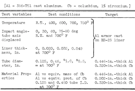
For armored tubes, the principal variables expected to influ- ence damage are: armor material and thickness, temperature, inner (corrosion resisting) liner material and thickness, angle of impact, and internal fluid (liquid or gas). The first phase of the program was therefore set up to include most of these variables. Tube configurations used were 356-T51 cast aluminum armor on a HS-25 inner liner and solid columbium -1$ zirconium alloy tubes. The specific shots called for in this first phase are outlined in Table 1. It was intended to conduct these fir- ings with з/32-in.-diam. glass projectiles at a nominally con- stant velocity. Equivalent protection thicknesses for the alu- minum and columbium tubes were determined according to the im- pact relations of Ref. !♦
Experimental Techniques Range and Monitoring Instrumentation
All of the tests to date were conducted on a ballistics range, which is fully described in General Motors-Defense Re- search Laboratories Rep. ER 62-201A.5 The basic equipment con- sists of a gun, a 20-ft free-flight range, and an impact cham- ber. The 0.22-in. caliber accelerated-reservoir light-gas gun is shown in Fig. 1. With this gun, it was possible to launch cylindrical plastic models to velocities of 32,800 fps or sa~
boted metal or glass spheres to velocities of 28,000 fps.
The accelerated-reservoir light-gas gun consists of a combus- tion chamber in which smokeless powder (lMR Series) is used to accelerate a polyethylene pump piston down a 20-ft-long, 1-in.- i.d. pump tube; and, in so doing, the pistons compress hydrogen as the driver gas to a pressure of nominally 20,000 to 30,000 psi. At this pressure, a break valve opens at the front end of the high-pressure coupling, and the hydrogen gas is released into the launch tube behind the model. As the model begins its travel in the 4-ft-long launch tube, the pump piston enters the tapered section of the high-pressure coupling. The front face of the pump piston is accelerated, and a constant base pressure is maintained behind the model during launch. The projectile is launched into the flight range and travels 20 ft before im- pacting the target. Prior to impact, the projectile travels through a surge chamber (in which the model is separated from the sabot), then into the velocity chamber. Here, the position and time of flight of the projectile are recorded at each of three spark shadowgraph stations (the octagonal chamber shown in Fig. 2). When the model interrupts a photo beam, electronic counters are started, and a short duration spark is set off, which exposes a film plate. The measurements of time and dis- tance between stations serve to determine the velocity of the projectile along its trajectory and, in particular, at the tar- get. The accuracy of the impact velocity determined in this manner is better than 1.0$.
The model flight is terminated in a specially constructed im- pact chamber (Fig. 2) that has six viewing ports. Two large windows are located in opposite sides of the target area, and four smaller windows are located on the front of the chamber.
The full size door acts as the rear wall of the chamber to al- low easy insertion and removal of the targets. The targets are held by a mount sitting on two rails on the floor of the cham- ber. This design allows placement of the target at a uniform longitudinal position with respect to the viewing ports. A variety of targets can be accommodated.
J. W. GEHRING AND S. LIEBLEIN
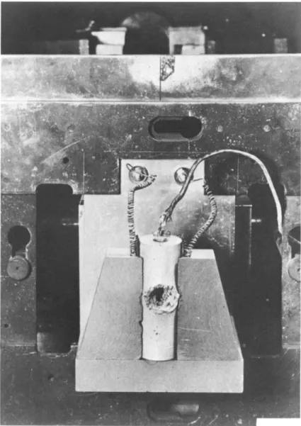
Since the investigation of the damage to a radiator target requires that the targets be impacted while under a simulated space environment, it was necessary to conduct the tests with the target at an elevated temperature and while in a simulated space environment of low ambient pressure. A typical target holder with the heater elements is shown in Fig. 3. This tar- get holder permitted the mounting of the radiator segments and the heating of them to temperatures up to 1500° F, The re- quirement for low ambient pressures was met by sealing the im- pact and velocity chambers and pumping down to pressures of less than 1 mm Hg. Air, or any number of desired gas mixtures, can be introduced into the chambers as test medium. In order to prevent oxidation of the heated targets in these tests, he- lium was used as the test gas* An Alphatron vacuum gage, cali- brated for helium gas, provided accurate pressure measurements within the chambers.
Photographic equipment was used to monitor the impact phenom- ena. A Beckman and Whitley Model 192 framing camera, capable of framing rates as high as 1.4 million frames/sec was used to record precisely the incoming projectile velocity; the phenome- na of impact flash; and the motion, velocity, and, in a rough sense, the quantity of minute particles being ejected from the crater. With this camera, it was also possible to observe, in a plane across the surface of the target, the growth of the crater in time. A typical B and W sequence of a l/8-in.-glass sphere impacting a space radiator segment at 23,000 fps is shown in Fig. 4.
The ballistics range is also equipped with four channels of flash radiographic equipment capable of viewing the impact at any four preselected times during the crater formation (Fig. 2).
Each X-ray pulse is 0.07 sec in duration at a peak output of 100 kv at 1400 amp. Flash X-ray instrumentation is particular- ly useful to "see" through the ejecta debris from the crater to determine the composition of the debris, i.e., vapor or solid particles. The combination of X-ray and the B and W camera optical record (Fig. 4) provides a detailed pictorial record of the process of crater formation. For the purpose of brevity, a typical flash radiograph is not included here.
Target Preparation
The assessment of target damage to the space radiator is com- plex and requires precise definition. Prior to testing any of the targets, each target was classified according to both mate- rial properties (as indicated by the manufacturer's specifica- tion) and by examination of the condition of the material.
Since the tests were aimed at simulating actual operating con-
ditions, each target was annealed for 8 hr at the test tempera- ture prior to firing the shot. In the tests conducted thus fax, the annealing and test temperature was 700° F. This pre- firing heat-treatment procedure was significant in that the aluminum targets underwent a phase change at 700° F after sev- eral hours anneal, which resulted in reducing the Brinell hard- ness number from a nominal 52 to a value of 20. The BBI is used here as a measure of the stregnth of the material; hence, the lower the В Щ , the more damage is likely to be caused on impact.^ Following the shot, the targets were cooled to room temperature and the damage was assessed.
Experimental Results
A complete tabulation of the results and identifying parame- ters for the data shots analyzed from the initial phase of the program is given in Table 2. Crater depth and dimple height were defined with respect to the original surfaces as shown in Fig. 5.
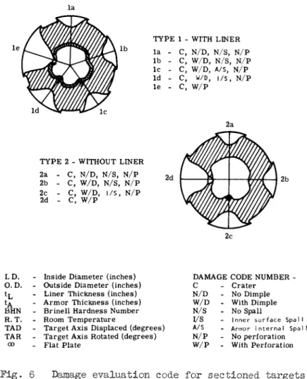
In addition to measurements of crater depth and diameter, targets were sectioned to show the extent and nature of the damage. To assist in the reporting of the observed damage, a damage evaluation code was established as shown in Fig. 6. The firings reported in Table 2 include most of the specific shots called for in Table 1 and additional exploratory or development shots into the subject targets that supply useful information.
The velocities achieved were in the range from 23,000 to 26,000 fps. The projectiles used had a nominal density of 2.7 g/cm .
The analysis of the experiments will be described under two major headings. The first will include qualitative observa- tions and comparisons. Quantitative assessment of crater depth and onset of spall will be made in a succeeding section.
Qualitative Observations
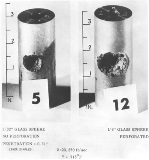
"Mass scaling. First, meteoroid mass scaling effects are con- sidered by comparing the damage caused by impact of two projec- tiles, one a з/32-in. glass sphere, each impacting an aluminum- armored HS-25 tube at a nominal velocity of 23,250 fps (Fig. 7).
The targets were at an average environmental operating tempera- ture of 715° F. These projectiles, weighing 0.016 and 0.040 g, respectively, fall into the meteoroid mass-frequency distribu- tion area of interest for radiators (Ref. l).
In Fig. 7 the з/32-in. glass sphere did not perforate the armor but did cause a dimpling of the inner liner. The l/8-in.
J. W. GEHRING AND S. LIEBLEIN
glass sphere, on the other hand, produced a larger crater diam- eter and complete perforation of the aluminum armor and the HS-25 liner. Hence, under these conditions of target tempera- ture and projectile density, the "ballistic limit" of this con- figuration can be defined as being between a meteoroid kinetic energy of 3.42X10¹⁰ to 8.5X101° ft-lb.
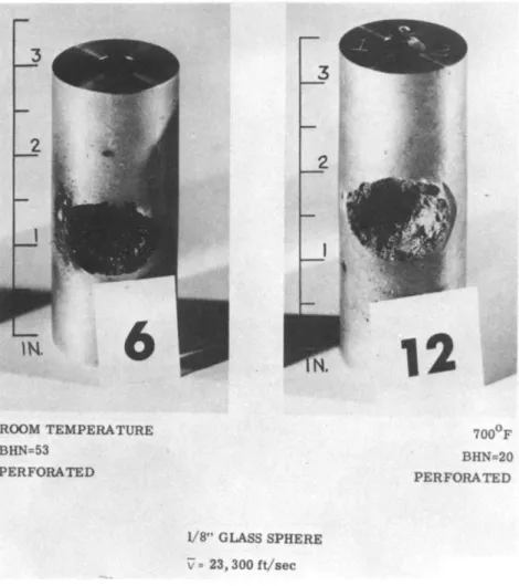
Target temperature. Although it was shown in Ref. 4 that by increasing the target temperature one could achieve greater damage to a simple metal plate target, it was not known how the increased temperature would affect a composite target such as those selected for these tests. In one test, a l/8-in. glass sphere was fired at an average velocity of 23,300 fps into each of two targets, one at room temperature, the other at 700° F (Fig. 8). In both cases the radiator complex was perforated.
However, in the case of the target at 700° F, the crater area was greater than for the target at room temperature. In addi- tion, the target at room temperature exhibited evidence of brittle spalling around the periphery of the crater indicative of the greater hardness (reflected by the Brinell hardness num number or lower ductility) of the material.
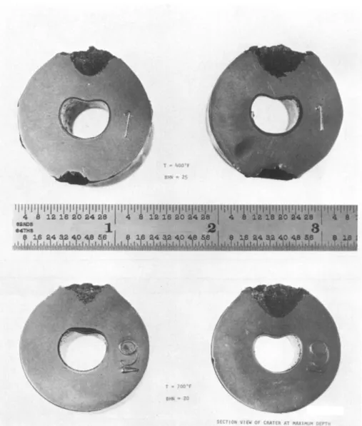
Aluminum targets impacted by a з/32-in. glass sphere at 400° F and 700° F are shown in Fig. 9. The increase in temperature resulted in an increase in both crater depth and diameter (cra- ter volume) but did not affect the height of the dimple in the liner. Sections of these targets taken at the center of the crater are shown on the right of Fig. 9. Again, the more duc- tile nature of the crater at the higher temperature is observed.
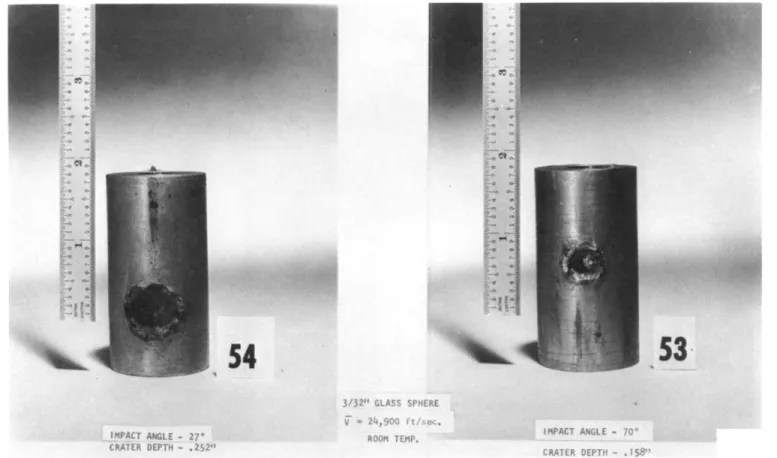
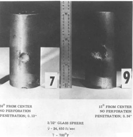
Impact angle. The next variable known to seriously affect the damage sustained by a target under hypervelocity impact is that of the attacking angle of the projectile to the target.
In Fig. 10 is seen the results of a з/32-in. glass sphere im- pacting aluminum armor targets at 27° and 70° from the normal at 24,900 fps at room temperature. (The photographs were taken normal to the resultant crater.) Oblique impacts at two angles for aluminum armor targets at 700° F are shown in Fig. 11. Sev- eral important results should be pointed out. First, all of the craters appear hemispherical, which assures that the impacts were typical of the hypervelocity impact regime. Secondly, the depths of penetration and the resulting crater volumes decrease as the impact angle increases. According to previous investi- gations with plate targets (Refs. 4 and 6), these effects can be accounted for empirically by measuring the energy of the at- tacking projectile in terms of its normal component of velocity.
Hence, as the angle of obliquity is increased, the energy of the projectile and corresponding depth of penetration should diminish with the cosine of the angle of impact.
The phenomenon of reduced penetration with angle of obliquity was also observed for the columbium tube targets (Fig. 12).
The results of Fig. 12 add further verification to the observa- tion that, as long as the normal velocity of the projectile does not fall below that required for hypervelocity cratering, the resultant crater will be a hemisphere, although much reduced in volume.
Internal damage. It was indicated earlier that radiator tube design should also be concerned with the possibility of inter- nal damage effects such as spalling and dimpling even in the absence of a penetration of the tube wall. The existence of such effects in columbium and aluminum tubes was indeed veri- fied, as indicated in Fig. 13. The deleterious effects result- ing from the injection of spalled fragments or the constriction of the fluid flow cannot be disregarded. Therefore, it is not sufficient to merely observe the crater and measure the depth of penetration in assessing target impact damage for applica- tion to radiator tube configurations.
Inner liner. The beneficial effects of having an inner liner can be seen in Fig. 14. One target was lined with a 0.020-in.- thick Haynes 25 liner} the second target had no liner, but the aluminum armor was made thicker, which kept the weight constant.
The inner HS-25 liner, although dimpled on the inside, prevent- ed spalling of metal into the tube. Fven when the projectile size was increased to a l/8-in. sphere, spalling was still pre- vented by the liner, although the dimpling was more severe, as shown on the right in Fig, 13. A tough inner liner is therefore of utmost importance in preventing spall particles from being ejected into the coolant-carrying fluid.
A typical impact crater section of an aluminum target with an HS-25 liner is shown in Fig. 15. Here, the spalling of the armor material beneath the crater itself can be clearly seen in addition to the dimpled HS-25 liner and the delaminating that has occurred between the liner and the armor. The manner in which the steel liner restricts the flaking and breaking away of the spalled particles is clearly depicted. Of a much more subtle nature, is the delaminating that has occurred at a dis- tance far removed from the dimpled section itself. A close-up view of points A and B in Fig. 15 can be seen in Fig. 16. Here at a magnification of 120 and 300, respectively, the crater sec- tion at points A and B can be seen in detail. At point A se- vere delaminating has occurred because the steel liner was pulled away from the armor and the bonding material failed. Section B shows another interesting observation. Here, it is believed that some delaminating is not associated with the formation of the crater but, rather, a failure of the bond during fabrication
J. W. GEHRING AND S. LIEBLEIN
of the radiator section. The different coefficients of expan- sion of aluminum and HS-25 no doubt resulted in a poor bond, since this effect was observed in all of the target sections prior to conducting the impact experiments. Delamination can affect radiator performance by reducing section strength and heat-transfer properties.
Tube effect. In applications of cratering data to radiator tube design, it has been assumed that the depth of penetration in flat-plate targets is representative of the penetration into tube walls of identical thickness. This was not found to be the case, and a significant effect of tube radius on impact damage was observed. Figure 17 shows impact into a columbium flat plate (radius =00) and into a 0.46-i.d. columbium tube of the same wall thickness under identical test conditions. Complete suppression of spallation was found in the case of the tube, although the depths of penetration were essentailly the same.
A similar result was obtained for an unlined aluminum tube as shown in Fig. 18. The results show the tubular section not perforated, yet the flat plate was completely perforated. A more dramatic example of the tube radius effect with the cast aluminum is shown in Fig. 19. The section photographs show the results of impact into tubes of widely different inside diame- ters (2.5 and 0.125 in.) under identical impact conditions and equal wall thicknesses.
The ability of the tubular target shape to sustain the impact damage is believed to stem from the fact that the shock propa- gation through the circular section is affected by more free surface. Consequently, the rarefaction waves that act to di- minish the intensity of the transient pressure pulse react more quickly, and thus weaken the shock, and consequently diminish its ability to cause spall on the under surface. If this ob- served tube radius effect is verified by further data, it would indicate considerable advantage in using small-diameter tubes.
Small inner diameter results in less required protection thick- ness, smaller vulnerable area (tube outer diameter), and lower tube weight for a given thickness.
Protection criterion. The final qualitative comparison to be drawn from the experiments conducted is the effect of damage protection criteria. Figure 20 shows an impacted columbium tube and a tube of aluminum armor and HS-25 liner designed for approximately equal weight of protective thickness. The poorer performance of the columbium alloy on this basis is indicated.
Figure 21 shows the results of impact into columbium and lined aluminum tubes designed for equal protection according to the relationships of Ref. 1. In both cases, no perforation was observed.
Quantitative Analysis
The previous section has presented a discussion of some of the principal qualitative observations obtained from the results of the initial firings. In addition to exploring and defining the phenomenological aspects of impact into radiator tube con- figurations , the program also has as its ultimate objective the generation of accurate analytical relations for use in design.
Although the initial phase of the program was not specifically- designed as a systematic parametric study, it was possible to obtain some preliminary quantitative information from the fir- ings.
It was pointed out early in the paper that a detailed mathe- matical formulation does not exist by which to predict accu- rately the damage by a meteoroid to space radiator configura- tions. The theoretical approaches of Bjork, Riney, Chou, and others have made significant advances in the analytical ap- proach; however, the treatments do not account in detail for the effects of increased target temperature, effects of varia- tions in target and projectile material, impacts at angles of obliquity, and the spa]ling, dimpling, or delaminating of thin and composite targets. A number of empirical relationships have been offered in the literature (Refs. 1, 4, 7, and 8) that do permit at least an approximation of the depth of penetration that might occur under limited conditions. These relationships for normal impact are
nl/3
dP
= РГЧ!)] k (1)
_к_ /iW
5dp U /
where K = 1.24X10"3 (cgs units) or of the form (Refs. 1 and 13)
For oblique impact, the normal component of velocity is used in both just mentioned equations; that is, Poc(cos Л )2/3. These relations, however, were obtained from impact into thick flat- plate targets, and its is not known to what extent they will be valid for tubular targets.
Some preliminary correlations pertaining to several factors
J. W. GEHRING AND S. LIEBLEIN
involved in the aforementioned relations for depth of penetra- tion have been established from the initial limited firings.
These relate to the effects of target temperature, angle of im- pact, target material, surface curvature (tube diam.), and liner thickness. In these plots, the values of depth of penetration used are the values corrected to a common velocity of 25,000 fps according to the 2/3 power of the velocity (designated by F*).
In addition, only penetration values for P/ta less than 0.75 were included in order to eliminate "thin-target" effects. Each data point is identified by its corresponding target number.
Angle of impact. The available data on variation of depth of penetration with angle of impact are shown in Fig. 22 for cast aluminum tubes at two temperatures. The best-fit variations for the (cos Л )2/3 relation are also shown in the figure. On the basis of these analytical relations, it was possible to normalize the data with respect to P at Л = 0 as shown in Fig. 23. It is thus seen that the data are very well repre- sented by the (cos Л )2/3 relation, which idicates the signifi- cance of the normal component of velocity in determining pene- tration depth for the aluminum tubes.
Target temperature. The available information on variation of depth of penetration with temperature for normal impact for identical conditions is shown for cast aluminum targets in Fig.
24. The value of P for normal impact was obtained by cor- recting for angle of impact according to the (cos À ) W3 relation as substantiated in Fig. 23. According to Eq. (l), depth of penetration should vary as (l/В^)-1-/^, and, according to Eq. (2), the variation should follow (l/Yt)1/^. The best fit of the
experimental data for the functional variations based on modulus of elasticity and Brinell hardness number is shown on the fig- ure. The data variation is seen to be reasonably described by both analytical relations.
Surface curvature. The existence of a surface curvature or tube radius effect on depth of penetration is strongly indi- cated in Fig. 25, which plots depth of penetration for normal impact against ratio of tube wall thickness to outer radius for aluminum and columbium tubes at 700° F. The lower limiting value of ta/R0 = 0 corresponds to a flat plate (zero curva- ture), whereas ta/R0 = 1 represents the upper limit of a solid cylinder (maximum curvature for a given thickness). It should be noted that the region of fall-off in penetration depth at high values of ta/R0 corresponds to practical values of tube inner diameter 0.50 in. and less). However, although no inner surface damage was observed for these high ta/R0 points, it is not known whether a quantitatively comparable decrease in required thickness will be observed for the avoidance of incipient spall-
ing or dimpling. However, it is clear from the photographs of Figs. 17-19 that a substantial decrease in spalling and dimpling can be expected for reduced tube size.
The extension of the fàired curves through the data points to
"^а/^о = 0 permits the normalizing of the data with respect to flat-plate penetration (P at ta/R0 = 0), as shown in Fig. 26.
The aluminum and columbium tubes fall essentially on the same.
curve, which indicates a possible uniform effect for both mate- rials. However, the establishment of a general empirical cor- rection relation for tube curvature based on these limited data is considered premature.
Although a good preliminary correlation has been obtained on the basis of the ratio of wall thickness to outer radius, this may not necessarily be the most significant physical parameter.
It can be reasoned that the size of the impacting particle might be significant, and a ratio of particle diameter to outer radius might also be involved.
Tube liner thickness. The effects of variation of tube liner thickness on depth of penetration and inner surface dimple height are shown in Fig. 27 for aluminum armor - HS-25 liner combinations of constant total weight (armor thickness decreases with increasing liner thickness). Depth of penetration is seen to increase with increasing liner thickness. The reason for this is not clear. Since the thick liner shots represent values of P/ta greater than 0.75, the increased penetration may be a
"thin target" effect, or the effect may be due to the inter- action of the liner on the shock variations in the armor. It is also observed that depths of penetration greater than the armor thickness can be obtained because of the dimpling of the liner.
Dimpling of the liner is seen to increase as liner thickness decreases; and, for some small value of liner thicknesses, the dimple bursts and spalling occurs. (The unlined tube showed considerable spalling.) As long as the liner is sufficiently thick to prevent rupture, it appears that there is a sizable variation in liner thickness that can be used at fixed total weight without risk of puncture, at least for the limits cov- ered in the tests.
Materials constant. The estimation of depth of penetration using the form of Eg.. (2) involves a materials constant y, which has been reported to vary from around 1.5 to 2.5 (Ref. 9).
In Ref. 1, T is taken as 2.0, and, in Ref. 8, y is 2.28. The data obtained in the initial phase of the program also can be utilized to obtain an indication of the applicability of these constants. FVom Eq_. (2), for a tube one can write
J. W. GEHRING AND S. UEBLEIN
where P/dp is based on the measured depth of penetration in the tube target, Pt/^oo is the correction for tube surface cur- vature established in Fig. 26, and the other values in the de- nominator are computed from material properties and tests condi- tions (for Ref. 1; ф = l/2; for Ref. 8, e = 2/3).
Values of X were computed for the applicable data points as indicated in Table 3 for aluminum and columbium targets. For the 16 cast aluminum targets, the average value of x was 2.27, in close agreement with the constant of Ref. 8. For the colum- bium targets, however, the calculated average values were sub- stantially lower than the equation values for both references.
For the equation of Ref. 1, (cp = l/2) calculated X = 1.49;
while for the equation of Ref. 13 (cp = 2/3, r = 1.79.
Similarly, the constant K in Eq. (l) was calculated for the aluminum and columbium targets as indicated in Table 3. For the 16 cast aluminum targets, the average value of K was 1.30X10" , which is slightly higher than the constant proposed. For the columbium targets, as before, the average value of K = 1.03X10"3 was substantially lower than the proposed constant. The differ-
ences between the values for the cast aluminum and the columbium alloy targets suggest that the X and K constants cannot be taken as a single value for a variety of target materials. How- ever, in view of the relatively few data points (4) for the colum' bium targets and the fact that these targets were heated in air for 8 hr at 700° F prior to impact and therefore became oxidized, further firings into columbium will be necessary to firmly estab- lish the existence of the differences in x and K.
The foregoing results, if substantiated, indicate a relatively smaller depth of penetration in columbium than previously esti- mated. For example, the difference in depth of penetration in aluminum and columbium calculated according to Ref. 1 may now be 35$> smaller. However, this does not necessarily mean at this point that the armor thickness (and consequently weight) re- quired to avoid critical damage (spalling or dimpling) will likewise be less. Further tests will be required to establish whether such is indeed the case.
Summary of Results
An exploratory experimental investigation of hypervelocity im- pact by glass spheres at approximately 25,000 fps into columbium
alloy radiator tube targets and cast aluminum tube targets with and "without Haynes-25 inner liners was conducted to explore ef- fects of target temperature/ angle of impact, liner thickness, tube diameter, and target material. The major tentative find- ings of the investigation based on the preliminary data are:
1) Hypervelocity impact can create spalling and dimpling of the tube inner surface in thicknesses substantially greater than the depth of the crater on the outer surface. Spalling and dim- pling therefore should be important considerations in tube armor design.
2) Significant differences between impact into tubes and plates were observed« In general, decreasing tube size (in- creased surface curvature) below an i.d. of about 1/2 in. tended to reduce spalling and depth of penetration. An advantage is indicated in using small-diameter tubes.
3) The presence of a thin Haynes-25 liner on the inside of the cast aluminum armor tended to suppress spalling and permit a greater depth of penetration without puncture. However, con- siderable dimpling can occur.
4) Variation of depth of penetration with impact angle ap- peared to correlate well with the normal component of the pro- jectile velocity.
5) Increasing depth of penetration with increasing target tem- perature up to 700° F appeared to correlate well with the vari- ation of velocity of sound (modulus of elasticity) or Brinell hardness in the target.
6) After using corrections for real tube effects, the depth of penetration in aluminum was in essential agreement with the predictions of several commonly used empirical relations. How- ever, the depth of penetration in columbium was substantially lower than that predicted.
References
1 Loeffler, I. J., Lieblein, S., and Clough, N., "Meteoroid protection for space radiators," ARS Preprint 2543-62 (Septem- ber 1962).
2 Bjork, R. L., "Meteoroids vs space vehicles," ARS J. 31, 803-807 (1961).
J. W. GEHRING AND S. LIEBLEIN
3 Jaffe, L. D. and Rittehhouse, J. B., "Behavior of materials in space environments," ARS J. 32_, 320-346 (1962).
4 Eichelberger, R. J. and Gehring, J. W., "Effects of meteor- old impacts on space vehicles/1 ARS J. 32, 1583-1591 (1962).
General Motors Defense Research Labs, Research facilities of the aerospace operations department/1 ER 62-201A, GM-DRL, Santa Barbara, Calif.
Bryan, G. M., "Oblique impact of high velocity steel pellets on lead targets," Proc. Fifth Symposium on Hypervelocity Impact 1, part 2, 511-534 (April 1962).
7
For additional papers on hypervelocity impact phenomena see:
Proc. Third Symposium on Hypervelocity Impact, Armor Research Foundation (October 1958); the Fourth Symposium on Hypervelocity Impact held at Eglin Air Force Base, Flor. (April I960); and the Fifth Symposium on Hypervelocity Impact held at the Colorado School of Mines, Denver, Col. (October 1961).
o
Charters, A. and Summers, J. L., "High speed impact of metal projectiles in targets of various materials," Proc. Third Hyper- velocity Impact Symposium, Armor Research Foundation, Chicago, 111. (October 1958).
q
Rodreguez, D., "Meteoroid shielding for space vehicles,"
Aerospace Eng. 19, 12; 20-13, 53-56 (December I960).
TABLE 1 PHASE I FIRING SCHEDULE
[Al = 356-T51 cast aluminum. Cb = columbium, Vfo zirconium. ] Test v a r i a b l e s Test c o n d i t i o n s Target Temperature
Impact angle- tube axis displaced Liner thick- ness, in.
Tube diam- eter, in.
Material Prop- erties
R.T., 400, 600, 700, 750° Pi 0, 30, 60, 75-80 deg
R.T. and 700° F
0, 0*020, 0.035, 0.049 at 700° F
0.125, 0.46, a1.0, a2.5, oo at 700° F
Al vs equiv. mass of Cb Al vs equiv. prot. of Cb
0.125 and 0.460 tube I.D.
at 700° F
Al armor cast on HS-25 liner
0.446-in.-thick Al 0.320-in.-thick Cb 0.446-in.-thick Al 0.202-in.-thick Cb 0.320-in.-thick Cb
aAl only.
TABLE 2 DETAILS OF PHASE I FIRINGS
01 CD 00
Target no.
1 5 6 7 9 12 31 32 37 38 39 40 41 45 53 54 66 69 71 75 79 83
Liner Liner Liner mate- I.D., thick- ri<
HS
HS-
al in. ness, in.
4,
-25 0.460 0.020
r r J
-25 0.460 0.020
i \
0.430 0.049 0.403 0.035
Armor mate- rial
Al
r
Cb Ob Ob Al Al Ob Cb Al
j
Armor I.D., in.
0.500
w
0.460 0.460
00
0.420
00
0.460 0.125 2.50 0.500
f
0.460 Armor thick- ness
*a>
in.
0.400
i r
0.200 0.200 0.320 0.465 0.446 0.320 0.320 0.446 0.400
0.371 T 0.343 0.446 0.446
Target temp,
Op
400 R.T. 732
700
ir 500 R.T.
R.T.
700 400 700
' '
R.T.
target hard-
ness (BHN) 36 53 37 37 36 37 121 125 134 36 35 135 135 36 37
1 56
Projec- tile diam. ,
in.
3/32 3/32 1/8 3/32 3/32 1/8 3/32
1
Projec- tile mass,
g
0.0160 0.0161 0.0413 0.0160 0.0160 0.0413 0.0160
0.0159 y 0.0160 0.0156 0.0151 0.0177 0.0.52
Projectile velocity.
fps
25,500 23,790 24,050 24,600 24,300 22,700 26,150 25,150 24,550 25,350 24,650 24,950 24,700 25,400 24,750 25,200 24,250 25,000 24,400 25,100 24,700
0 1 CO CD
Target Impact no. angle
\ deg
Crater Crater diameter, depth,
in. P, minimum maximum m .
I.D.
below dimple,
in.
Dimple height
m .
K
р
Ач
Youngf smodulus, Yt, psi
Damage code
P corrected to 25,000
fps P*, in.
1 5 6 7 9 12 31 32 37 38 39 40 4 1 45 53 54 66 69 71 75 79 83
5 8 16 68 15 0 40 12 27 5 13 0 70 27 26 15 0 0 0 20
0 . 4 5 0 . 5 0 0 . 5 2 0 . 3 1 0 . 5 0 0 . 6 4 0 . 2 8 0 . 3 1 C 0 . 5 0
C 0 . 3 0
C 0.48
C 0 . 5 0 0 . 5 3 0 . 5 0 0 . 4 9 0 . 5 2 0 . 4 5 0 . 4 1
0.30 0.48 0.28 0.36
0.52 0.56 0.54 0.36 0.58 0.78 0.38 0.33 0 . 5 6 3
0 . 3 1 3
0 . 5 0 0 . 5 5 0 . 5 9 0 . 5 1 0 . 5 5 0 . 6 0 0 . 5 3 0 . 4 6
0 . 2 9 9 0 . 3 0 6 0 . 1 2 7 0 . 3 1 5 0 . 1 5 0 0 . 1 3 4 0 . 2 9 0 0 . 1 3 5 0 . 1 0 9 0 . 3 5 1 0 . 1 5 8 0 . 2 5 2 0 . 3 1 4 0 . 3 0 6 0 . 3 1 9 0 . 3 7 2 0 . 2 8 9 0 . 2 1 2
0 . 3 4 0 . 1 2 0 . 37 0 . 09
PERFORATED 0 . 4 6
0 . 3 4 0 . 1 2 PERFORATED PERFORATED
PERFORATED 0. 39 0 . 05 0 . 1 1 0 . 0 1 5 0 . 4 6
0 . 3 7 0 . 3 1 0 . 3 7 0 . 3 6 0 . 3 3 0 . 3 6 0 . 1 0
0 . 0 9 0 . 1 5 0 . 0 9 0 . 0 7 0 . 0 7 2 0 . 1 0 0 . 0 2 5
0.747 0.765 0 . 3 1 8 0 . 7 8 7
9 6, 10
6, 4x10 6 6X10⁶ 9x10 6 8X10⁶
0 . 7 5 0 1 5 . 8 X 1 06 0.420
0.624 0 . 4 1 3 0 . 3 4 1 0 . 7 8 7 0 . 3 9 5 0 . 6 3 0 0 . 7 8 4 0 . 7 6 5 0 . 8 6 0 1.08 0 . 6 4 7 0 . 4 7 6
6 . 8 X 1 06 6.8X10⁶ 1 5 . 8 X 1 06 15.8X10⁶ 8 . 8 Х Ю6 1 0 . 9 X 1 06 1 0 . 9 X 1 06 6 . 8 x 1 06 9 . 4 X 1 06 6.8X10⁶
l e l b l e 2c 2d 2c 2c 2d
2c
l c l c
0 . 2 9 5 0 . 3 1 6 PERF 0.128 0.320 PERF 0.146 PERF 0.136 0.288 PERF 0 . 1 3 6 0 . 1 1 0 0 . 3 4 8 0 . 1 5 9 0 . 2 5 1 0 . 3 2 0 0 . 3 0 6 0 . 3 2 3 0 . 3 7 2 0 . 2 9 1 0 . 2 2 6
CO -<
CO -i
m Co
CO >
O
J. W. GEHRING AND S. LIEBLEIN
<D -P cd
cd O « ЮЮЮЮЮЮЮЮЮ 1 1 1 I I I I I I ooooooooo
мюомюмюмю ннннннннн Ю Ю Ю tO Ю 1 1 1 1 1 о о о о о » т-{ г-\ г-\ г-\ Н • X X X X X . CO -чН 00 Ю Ю 00 Н ^Н 00 00 н н н н н ю о н X о ю н
<L) -Р Сб Н
о Н cd о << 00 о о J4 Н юююююююю ю ooooooooo
• HCDCD^OLOCD^HO ♦ ^ншооююсоюспоо ЮЮЮСО^ЮОО^НСО ю ю ю ю ю о о о о о Н r-j Н Н Н • X X X X X ♦ Н CO ^Н О Г-. ^ ^ С0 № Н CD CD LQ ^ LO ooooooooo o o o o o
(Ü -p cd H Ü H cd o s to 00 LO Ю 00 CD 00 00 co H 00 Ю 00 CD 00 Ю 00
00 00 o 00 CD 00
00 t> ^ 00 -Ф ^H DO 00 00 00 00 Ю oo co 00 H H 00 O H 00 00 00
00
<
^ LO 00 I> ^H CDCDOOCD^HCDCDOOCDLO^^HcnOCOCO
H O H O H H O H H H H
С7)ШСОЮСООСПСОО^ЮСООСОСОГ-0 Н1^00ЮЮООСОСОЮООСТ)ОООЮ1^-юнюнюююнооюююююоооо
нюю^сп^сою^соспНшю^ю 00LOLOLOCDCDl>-!^C0C0CO
600
Colurribium - 1% Zr
o
Target Exp.
no.
C a l c u l a t e d , 2 / 3 /
.P. /y cos л \2/5/рр \Ф^ Л d
p V
Ct / W VW
Calculated Calculated Calculated
Г (E/B cos2A)2/3 K
ф = l / 2 ф = 2/З ф = 1/2 ф = 2/3 31
37 40 41
1.60 1*43 1.94 1.16
0.819 0.935 0.770 0.935
0.685 0.783 0.645 0.783
Av.
1.96 1.53 1.23 1^24:
1.49
2.34 1.92 1.42 1.48 _ 1 . 79 _
0.290X10³ 0.334X10³ 0.344X10³ 0. 340ХЮ3
1.27xl0~3 1.03X10"3 1.00X10"3 0.82x10"3 _ i . 0 3 x _ i p -3
m *J co
■<
Co ■H
m
CO
Co -a >
O
( ..ansívr ïlis*I. P r e s s u r e Tapered Coupling
G5 O to
Gas Manifold Control Panel
Com bust ion C ham l ч • r
o m
z: z o >
z o
r— m
Z
PKR S F f O N I
CO
o
TO CO
>
n
o
J. W. GEHRING AND S. LIEBLEIN
Fig. 3 Target holder with heater elements
P R O J E C T I L E IMPACT FL FLASH
- 1 . 2 M S E C » H SEC
E J E C T A + 1.2 Д SEC
+2, 5 M SEC +6. 2 M SEC + 11. 1 M SEC
+21. 0 M SEC *-33,4 M SEC *44. 5 M SEC
F i g . 4 B a n d W s e q u e n c e of a l / 8 - i n . - d i a m . g l a s s s p h e r e im- p a c t i n g a s p a c e r a d i a t o r segment a t 2 3 , 0 0 0 f p s
J. W. GEHRING AND S. LIEBLEIN
I . D . BELOW DIMPLE HEIGHT OF DIMPLE CRATER DEPTH CRATER DIAMETER LINER THICKNESS
Fig. 5 Notation for target damage measurements
TYPE 1 - l a - C, l b - C, l c - C, Id - C, l e - C,
WITH LINER N / D , N / S , N / P W/D, N / S , N / P W/D, A/S, N / P
W/D, i / s , N / P W / P
TYPE 2 - WITHOUT LINER 2a - C, N/D, N/S, N/P 2b - C, W/D, N/S, N/P 2c - C, W/D, l/S, N/P 2d - C, W/P
2d
I.D.
O.D.
*L *A BHN R. T.
TAR TAD oo
Inside Diameter (inches) Outside Diameter (inches) Liner Thickness (inches) Armor Thickness (inches) Brinell Hardness Number Room Temperature
Target Axis Displaced (degrees) Target Axis Rotated (degrees) Flat Plate
DAMAGE CODE NUMBER N / D c
W/D N/S A/S Vs
N / P W / P
- C r a t e r - No Dimple - With Dimple - No Spall
I n n e r s u r f a c e S p a l l - Armor i n t e r n a l S p a l l - No perforation - With Perforation
Fig. 6 Damage evaluation code for sectioned targets
J. W. GEHRING AND S. LIEBLEIN
3/32" GLASS SPHERE NO PERFORATION PENETRATION = 0. 31"
LINER DIMPLED v»23, 250 ft/sec
T - 715°F
1/8" GLASS SPHERE PERFORATED
Fig. 7 Projectile size effects, aluminum with HS-25 liner tar- gets, armor thickness 0.400 in., liner thickness 0.020 in.
12
ROOM TEMPERATURE BHN=53
PERFORATED
700°F BHN-20 PERFORATED
1/8" GLASS SPHERE v* 23,300 It/sec
Fig. 8 Target temperature effects, R. T. and 700° F. 0.400- in. aluminum armor with 0.020-in.-liner targets
J. W . GEHRING AND S. LIEBLEIN
1|1|1|1|1|1|1|Ч1|1|ф1ф|1 4 8 12 18 20 24 28 з&тз
1
84TMS
8 IB 24 aa 40 48 58 1 8 IB 24 ШЙ 40 €8 '58 l'^в\ l e ' S À Ш;''40 4.8 'Ш Í
3
ч '&'Ш ICTiQU \>!£W OF « Д Т Е Н AT MAXíH
Fig. 9 Target temperature effects, 400 and 700u F. 0.400-in.
aluminum armor with .020-in.-liner targets, з/32-in.
diam. glass projectile at 24,600 fps
54
—I m
CO
>
П
O
IMPACT ANGLE ~ 2?Si CRATER DEPTH - ЛЬ2"
3/32» GLASS SPHERE
\7 * 24,900 ft/sec,
ROOM TEHP. IMPACT ANGLE - /СУ
CRATER DEPTH ~ . !58"
Fig, 10 Impact angle effects, 0.500-in. i.d. aluminum, 0.400
J. W. GEHRING AND S. LIEBLEIN
<№ 9
88° FROM CENTER NO PERFORATION PENETRATION: 0.13"
15° FROM CENTER NO PERFORATION PENETRATION; 0. 34"
3/32" GLASS SPHERE v = 24,450 ft/sec
T = 700°F
Fig. 11 Impact angle effects, 0.500-in. i.d. aluminum 0.400 in.
thick, HS-25 liner
40° FROM CENTER NO PERFORATION
PENETRATION; . 150"
12 FROM CENTER PERFORATED
3/32" GLASS SPHERE V=25,650 ft/sec
f - 70O°F
P i g . 12 I m p a c t a n g l e e f f e c t sy 0.400-in. i.d. columbimn 0.200 in. thicks no liner
J. W. GEHRING AND S. LIEBLEIN
ALL COLUMBIUM 0. 20" THICK WALL 0. 40" AL. ARMOR, 0. 02" HS-25 LINER
3/32" GLASS SPHERE 1/8" GLASS SPHERE
TUBE 1,0, = ЛШ{ v* 24,700 ft/sec
T - 700°F
Fig. 13 Internal tube damage
38
0. 40" Al. ARMOR 0. 02" HS-25 LINER NO SPALL ON INSIDE
NO PERFORATION DiHPlE
0.47" AL ARMOR, NO LINER SPALL ON INSIDE NO PERFORATION 3 '32" GLASS SPHERE
v - 2 4 , 650fi see f - 715°F
Fig. 14 Liner effects, aluminum targets
J. W. GEHRING AND S. LIEBLEIN
*Щ]
if'
a t /
* - л~ *
#v-
INCHES
Fig. 15 Typical impact crater section, aluminum with HS-25 liner target
DE LAMINATION OF ARMOR, BOND,
AND HS-25 TUBE
SECTION B (300X)
LINER
>(HS-25)
SECTION A (120X)
Fig. 16 Armor-liner interface photomicrographs (Ref. Fig. 15)
J. W. GEHRING AND S. LIEBLEIN
BACK
37
0,320" ПИСК WAI 1 ,460 f.o.
N4) SPAÏ 1 UN ÏN-UM
\ 0 Pi H! <Jb- \ I 4*' 3 .*.»" í.l.ASS M'HKifK
V - 24,500 f t / s e c .
Fig. 17 Target radius effects,, СЪ targets
'•. K..V Т Ш Г К WALL,
■*0 PFJIFOPATfUX
Л 2 0п !.D. 0«446í ! THICK P L A T E P E R F O R A T E D
3 32" GLASS SPHERE v* 25,000 H ягс
T s 7 o nuF
Fig. 18 Target radius effects, СЪ targets
CD to o
2.5fï 1.0.
PENETRATION - . 3 1 5 "
INTERNAL SPALL
83
V * 24,000 FT/SEC.
T « 600eF
.125" I.D.
PENETRATION - ,212if N0 SPALL
O
ГП
>
Z o
Fig. 19 Tube radius effects. Aluminum armor^.0.446 in. thick, no liner
Л60и LD, ,200" THICK WALL ALL COLUMBIUM
PERFORATED
.500n 1.0, Л00" THICK WAIL AL. ARMOR, B>S~2r> I IN! R
PENETRATION; .315"
3-32" GLASS SPHERE v ^ 24, 800 ft see
T - ?00°F
Fig. 20 Comparison of equal unit weight aluminum and columbium targets
J. W. GEHRING AND S. LIEBLEIN
PENETRATION; .306" PENETRATION; .135"
3 / 3 2 " GLASS SPHERE 4' - 2 4 , 5 0 0 f t / s e c
T - 7i"»° F
F i g . 21 Comparison of equal p r o t e c t i o n schemes (NASA Ref. l ) , i . d . c o n s t a n t
QL
o .35i
.30h-
.25H
.20H z
Q_ •" 5|
u_ o X CL .10) Ш Q
.05
—
ъл
p
-
,
k
*?и66
* ^ ^ Q 5 4 \
(COSX)2/3-
, 1 L _
O ROOM TEMP A 700° F
ycosx)2'3
w
5 3 0 V \
_ J . J
0 30 60 90 IMPACT ANGLE, X, DEG FROM NORMAL
22 Variation of penetration depth with impact angle, cast aluminum tubes, з/32-in.-diam. glass particle, 25,000 fps
<
1.0
.8
.6
.4
.2 5V
- - -
9
i - 6 6
1
V 700° F
\r(COSX)2/3 5 3 - \ _7
0 30 6 0 9 0 IMPACT ANGLE, X, DEGREES FROM NORMAL
23 Normalized variation of depth of penetration with im- pact angle, cast aluminum tubes, з/32-in.-diam. glass projectile, 25,000 fps
J. W. GEHRING AND S. LIEBLEIN
.44i—
<
<
0Ć.
"0 200 400 600 800 1000 TARGET TEMP, °F
24 Variation of depth of penetration with target tempera- ture . Cast aluminum tubes, normal impact; з/32-in.- glass projectile, 25,000 fps
.32 .28 .24
Zl69
<
en \-
LU Ш z
Q_ LL O X 0 -LU O
. 2 0
.16
(
.12
OR
-
)37 COLUMBIUM
1 1 - 4 ?
1
Ч.41
N
.2 .4 .8 1.0 1.2 1 1
CURVATURE PARAMETER, ta/R0
g. 25 Variation of depth of penetration with tube radius, 700° F з/32-in.- diam glass projectile, 25,000 fps
z o
<
0Ć.
1.2
1.0Ф
* 8 ж4-
<
cr o z
Al TARGETS Cb TARGETS
37 369
.2 .4 .6 .8 1.0
CURVATURE PARAMETER, ta/ R0
Fig. 26 Variation of normalized depth of penetration with tube radius. 700° F; з/32-in.-diam. glass projectile, 25,000 fps
ARMOR THICKNESS 71
.01 .02 .03 .04 .05 LINER THICKNESS, IN
Fig. 27 Variation of depth of penetration and dimple height with liner thickness. Cast aluminum on HS-25 equal weight configurations, з/32-in.-diam. projectile, 25,000 fps, 700° F