1
Optimization of a wall thickness of a pressure vessel
A. Erdős, K. Jármai
University of Miskolc, Hungary
ABSTRACT: The structure and the manufacturing of pressure vessels is considered. The optimum design of a wall thickness of a pressure vessel is made on different temperatures 200-500 oC and inner pressures 100-200 bars. Using different heat resistant steels, one can get different solutions. Both the mass and the cost of the structure is calculated. The optimization is made by the Generalized Reduced Gradient method in MS Excel.
1. INTRODUCTION
In this article we deal with the optimum design of a wall thickness of a pressure vessel. As defined pressure vessels with rigid walls are designed to store liquid or gas consistency with a higher pressure than the atmospheric. Pressure vessels are made of sheet materials, in most ofthe cases by welding, very rarely riveted. But riveting used only in places where welding is not possible for any reasons.
Since pressure vesselsare dangerous equipment, so this steel used as a base material must have certificate of evidence of an expert. In any case, non-resilient steel cannot be used as a base material in the pressure vessel.
2. STRUCTURE AND MANUFACTURE OF PRESSURE VESSELS
The cylindrical portion of the container is the mantle made of cut-to-size sheet material. They are bent in cylindrical shape and welded to the dowel-shaped plate ends. If the container is sufficiently large, the jacket is made of several cylindrical pieces and has several lengths and cross-seams. In such cases, the longitudinal seams must be offset from each other, at least three times the thickness of the sheet or 100 mm. To connect multiple cylindrical segments, the plates are welded with a blunt collision "X" or
"V" seam. In these vessels, it is forbidden to make interlaced joints due to the tension congestion and, secondly, to the undetermined load distribution of the two weld seams. For sheet rolling because sheet thickness is significant, therefore, a hydraulic three-cylinder roller is the most appropriate choice, as this type of machine has a rollable sheet thickness between 25 and 180 mm.The rollable length is typically between 2000 and 4000 mm on such machines.For larger diameters, vertical and lateral support may be required to avoid deformation of the plate.
The bottom of the vessel is connected to the mantle, which serves to seal the container. The applied dish bottom configurations are: flat, elliptical, hemispherical, shallow or deep envelope basket curve.
This process is carried out on a suitable container bottom embossing machine. For example, the Italian Boldrini factory manufactures these and other plate machining equipment.
The flat dish bottom design is usually used to seal pressure-free tanks because it is the most unfavourable terms of strength. The hemispherical shape is the most favourable, but its production is the most difficult, so it's the most expensive. In practice, the two types of basket curves are most commonly encountered. From the two basket curves, the deep covering is more popular, because its strength is greater, so in the same operating conditions, material and cost savings can be achieved. The
2
casing and the bottom of the bowl are almost always unbounded. The bottom of the container is manufactured by moulding procedure.
Various pipe connections must be provided on the shell or bottom of the tanks. For example:
pressure and temperature gauges and other auxiliary and safety fittings.
Both lying and standing tanks must be supported. These support points result in an additional tension in the wall, which is to be considered in some special cases during the scaling. In case of lining tanks, the supports should be symmetrically positioned so that the torque maximums are distributed equally to the supports. The design of the support can be two types, with brackets or ribs stiffened. One of the most important support methods is the saddle support.
Other solutions suitable for supporting a further stationary cylindrical container include the apparatus foot, appliance pad, ring and skirt. Each of these support solutions, hasa significant additional tension, which is still a problem to date.
Avoidance of tension peaks and switching from concentrated load transfer to distributed can be provided by using cotyledons, nowadaysthis is the most popular solution.
The main advantage of this support mode is that it does not pass the bending moment to the container, and its preparation is simple.
The test container an ammonia synthesis converter. It is produced from the elements of ammonia, the reaction is an equilibrium, therefore it is also valid for ammonia formation and decomposition. The typical temperature range for ammonia formation is between 200 °C and 700 °C and the pressure range is between 980665 Pa and 98066500 Pa. The three major methods of ammonia synthesis are low pressure medium pressure and high pressure. Among them, the most common is the medium pressure process (also known as the Haber-Bosch process), which corresponds to the economic optimum. The synthesis reaction itself is exothermic and the synthesis reaction decreases with volume, therefore the space velocity decreases along the progress of the reaction. The correct converter and catalytic bed design should be such that it allows to optimize the temperature curve. Any type of converter should be sought.
The converters have two well-spaced parts in the intricate interior and the outer pressure-resistant casing. In this article we deal with the latter with the high-pressure jacket. The jacket shall be so designed that the inner parts can be removed in one piece. Initially, the jacket was made from a single piece by forging, and with the size increase the appearance of other technologies was needed.
The high-pressure jacket must be made of weldable material. The high-pressure body may be in contact with the synthesis gas at a temperature of 400 to 500 oC, and therefore the use of heat-resistant steels may be justified, but hydrogen corrosion due to the hydrogen content of the synthesis gas may also be a problem. The high pressure and the shells in the shell provide strict requirements against the gas tightness of the welded and bolted joints. It is particularly important that due to the leakage, do not deviate too much from the optimal temperature curve. These connections are best served by frequent downtime and restarts.
3. DETERMINATION OF THE WALL THICKNESS
The following relationship is used to determine wall thickness:
(1)
The numbersin the formula are the following: isthe outer diameter of the cylindrical shell of the converter, is the pressure inside the converter, is the yield strength of the tested steel, and the value of it is depends largely on the temperature, is the factor of safety, is the welding factor, and finally the is contains a variety supplements, for example the corrosion supplement. During the calculations, wetook the value of c to 0, and the value of is 1,5 and the value of is 1.
The value of the outer diameter is 1400 mm bases of an existing equipment. Additional geometric parameters are as follows: the height of the converter is 16700 mm, the inner diameter is 1200 mm.
Other parameters are not essential for the calculations.
3
Since no specific values of the pressure are given limits only, so during the calculations wechanged the value of the pressure, exactly three different values, which are the following 100 bars this is p1, 150 bars is p2 and 200 bars is p3. Similar to the temperature, there are no specific values only limits are given, so wehave selected three different values the T1 is 200 oC, the T2 is 400 oC and the T3 is 500 oC.
Although the temperature is not included in the formula as a specific factor, yet it has a major role in the value of the yield limit. Wemade calculations for all temperature and pressure pairs. This means nine different calculations for each steel and because Weexamined twenty different heat resistant steels, the result is all over 180 calculations.
The next step is the optimization process. In the knowledge of the volume and the density of the given heat-resistant steel, it means minimizing the weight of the container. Optimization is carried out on the volume, the value of which cannot be changed too much, because the gas residence time cannot be changed to a greater extent, even if it is not possible to follow the optimal temperature curve.
Therefore, the size of the converter may vary by up to ± 10%. Assuming a proportional change over the whole converter, both the outer and inner volumes can differ from the original by ± 10%.
The original inner volume of the converter:
600 16700 1,8887 10 (2)
and the outer:
700 16700 2,5707 10 (3)
In these formulas the components are the following: r is the radius of the inner diameter of the converter, R is the outer and the h is the height of the converter.
Assuming that 10% is valid for both the outer and inner volumes, this can be used to calculate the lower and upper limits of the volume values both for internal and external volumes.
The limits of internal volume:
0,9 1,1 (4)
1,6983 10 2,0757 10 (5)
Boundaries of outer volume:
0,9 1,1 (6)
2,3137 10 2,8278 10 (7)
The limits of these volumes can be used to count the limits of the radiuses besides the condition that the tank height is kept constant:
, 568,9499 (8)
, 628,9978 (9)
, 734,1607 (10)
, 664,0799 (11)
Below these limits must be the diameters of the container, provided that the difference is equal to the wall thickness, which was determined in advance according to the above formula. Therefore, wall thickness can be described as the difference between the outer and inner radius of the cylindrical part.
The wall thickness can be recalculated according to the condition system. The Microsoft Excel’s Solver extension has been used for this purpose.
During this recalculation the Solver completes the calculation of the wall thickness including the following conditions:
the main purpose is to minimize the volume of the basic material of the jacket, so the volume will be the objective function of the procedure, the specified wall thickness must be less than the difference between the maximum outer diameter and the inner minimum, the wall thickness after optimization must be greater than or equal to the pre-determined wall thickness.
4
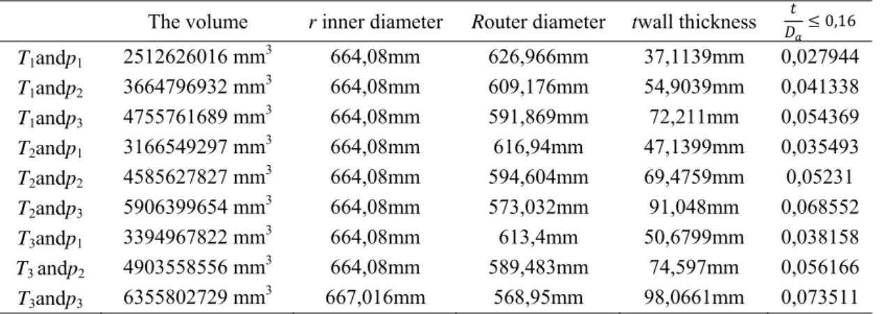
The optimization procedure has been carried through for all temperature and pressure pairs.The results of the calculations are shown in Table 1.
Table 1. Optimization results for different temperature and pressure
The volume r inner diameter Router diameter twall thickness 0,16 T1andp1 2512626016 mm3 664,08mm 626,966mm 37,1139mm 0,027944 T1andp2 3664796932 mm3 664,08mm 609,176mm 54,9039mm 0,041338 T1andp3 4755761689 mm3 664,08mm 591,869mm 72,211mm 0,054369 T2andp1 3166549297 mm3 664,08mm 616,94mm 47,1399mm 0,035493 T2andp2 4585627827 mm3 664,08mm 594,604mm 69,4759mm 0,05231 T2andp3 5906399654 mm3 664,08mm 573,032mm 91,048mm 0,068552 T3andp1 3394967822 mm3 664,08mm 613,4mm 50,6799mm 0,038158 T3 andp2 4903558556 mm3 664,08mm 589,483mm 74,597mm 0,056166 T3andp3 6355802729 mm3 667,016mm 568,95mm 98,0661mm 0,073511 This wall thickness is only true if there is a condition of thin walling that covers the next, the wall thickness and outer diameter of the container should be less than 0,16. Written this in the form of a mathematical relation:
0,16 (12)
In case this relationship does not exist, the pressure vessel cannot be considered as thin wall and the above formula will lose its wall thickness, instead the formulas applicable to thick walled vessels should be applied.These ratios are included in the rightmost right column of the Table 1.
The optimized wall thicknesses and the geometry of the container are available, and with the volume of the pressure vesseland with the density of steel, the weight of the equipment can be easily calculated.In possession of this and with the price per kilogram for each heat resisting steels, and with the combination of the two values we get the cost of the base material of the jacket. The resulting data show the dependence of the weight and cost on the temperature and pressure.This can be seen in Table 2 using X12CrMnNiN 17-7-5.
Table 2. The weight and cost of the pressure vessel for different temperature and pressure The weight The cost of the material T1 and p1 23316,67 kg 11728285 HUF T1 and p2 33841,74 kg 17022396 HUF T1 and p3 43683,47 kg 21972783 HUF T2 and p1 27880,24 kg 14023761 HUF T2 and p2 40196,64 kg 20218911 HUF T2 and p3 52851,15 kg 26584129 HUF T3 and p1 29717,74 kg 14948024 HUF T3 and p2 42730,2 kg 21493292 HUF T3 and p3 57409,14 kg 28876798 HUF REFERENCES
ÁrpádZsáry2003.Machine elements I, NemzetiTankönyvkiadó, (in Hungarian) GyörgySomló1974.Chemical technology processes, Tankönyvkiadó, (in Hungarian)