Budapest University of Technology and Economics Faculty of Mechanical Engineering
Department of Polymer Engineering
DEVELOPMENT OF ALL-POLYPROPYLENE COMPOSITES FOR INJECTION MOULDING
PhD thesis
By Ákos Kmetty
MSc in Mechanical Engineering Supervisor Tamás Bárány, PhD
Associate Professor
Budapest, 2012
2 Acknowledgements
I would like to express my thanks to my supervisor, Dr. Tamás Bárány for his attention and relentless support of my studies, and his guidance towards a deeper scientific way of thinking. I appreciate the valuable help and advice of Professor József Karger-Kocsis, who has supported my studies from the beginning. I would like to thank to Professor Tibor Czigány for his assistance and assuring the friendly atmosphere during my work. I would like to thank the help and advices of Dr. József Gábor Kovács, Dr. Tamás Tábi and Dr. László Mészáros. I am grateful to my colleagues and friends at the Department of Polymer Engineering for their significant help.
I express my thanks to C. M. Wu for his help, to Dóra Tátraaljai and Dr. Enikő Földes for their help in the FTIR measurements and to Csaba Érseki for his help in development of the special extrusion die. I express my thanks to my students who helped a lot my work.
I express my thanks to the Hungarian Scientific Research Fund (OTKA K75117) for the financial support, to Arburg Hungary Ltd. for the Arburg Allrounder 370S 700-290 machine and to MTA–BME Research Group for Composite Science and Technology for the support.
Finally, I would like to thank my wife, parents and friends for their continuous support in reaching my goals.
The work reported in this thesis has been developed in the framework of the project "Talent care and cultivation in the scientific workshops of BME" project. This project is supported by the grant TÁMOP - 4.2.2. B-10/1--2010-0009.
This work is connected to the scientific program of the "Development of quality-oriented and harmonized R+D+I strategy and functional model at BME" project. This project is supported by the New Széchenyi Plan (Project ID: TÁMOP-4.2.1/B-09/1/KMR-2010-0002).
3 Alulírott Kmetty Ákos kijelentem, hogy ezt a doktori értekezést magam készítettem, és abban csak a megadott forrásokat használtam fel. Minden olyan részt, amelyet szó szerint, vagy azonos tartalomban, de átfogalmazva más forrásból átvettem, egyértelműen, a forrás megadásával jelöltem.
Budapest, 2012. november 15.
Kmetty Ákos
4 A doktori disszertáció bírálata és a védésről készült jegyzőkönyv a
Budapesti Műszaki és Gazdaságtudományi Egyetem Gépészmérnöki Karának Dékáni Hivatalában megtekinthetőek.
5 TABLE OF CONTENT
1. INTRODUCTION ... 10
2. LITERATURE OVERVIEW ... 12
2.1. SINGLE-COMPONENT SRPMS ... 13
2.1.1. One-step (in-situ) production ... 13
2.1.2. Multi-step (ex-situ) production ... 17
2.1.2.1. Solid phase extrusion ... 18
2.1.2.2. Super drawing ... 20
2.1.2.3. Rolling ... 20
2.1.2.4. Gel drawing ... 21
2.1.2.5. Orientation drawing... 21
2.1.2.6. Hot compaction ... 22
2.1.2.7. Production by film stacking ... 27
2.2. MULTI-COMPONENT SRPMS ... 30
2.2.1. Single-step (in situ) production ... 30
2.2.1.1. Multi-component extrusion yielding self-reinforced structures ... 30
2.2.1.2. Multi-component SCORIM/OPIM ... 31
2.2.2. Multi-step production ... 31
2.2.2.1. Consolidation of coextruded tapes ... 31
2.2.2.2. Film stacking ... 34
2.3. FIBRE REINFORCED POLYMER COMPOSITES BY CONVENTIONAL INJECTION MOULDING ... 38
2.3.1. Shrinkage and warpage of the injection moulded products ... 39
2.3.2. Effect of the fibre length and content on the properties of injection moulded fibre reinforced composites ... 40
2.4. SUMMARY OF THE LITERATURE, AIMS OF THE DISSERTATION ... 41
3. EXPERIMENTAL PART ... 44
3.1. PRELIMINARY TESTS ... 44
3.1.1. Mixing method ... 45
3.1.2. Extrusion coating method ... 45
3.2. MATERIALS, PROCESSING AND TESTING ... 48
3.2.1. Materials ... 48
3.2.2. Manufacturing of the pre-impregnated material ... 52
3.2.3. Injection moulding ... 55
3.2.4. Testing methods ... 56
3.3. RESULTS AND DISCUSSION ... 59
3.3.1. Relaxation of single fibres ... 59
3.3.2. Random polypropylene based all-PP composite (all-PP(R)) ... 60
3.3.3. Elastomeric polypropylene based all-PP composite (all-PP(E)) ... 76
6
4. SUMMARY ... 86
4.1. THESES ... 89
4.2. APPLICABILITY ... 90
4.3. FURTHER TASKS TO BE SOLVED ... 90
5. REFERENCES ... 91
6. APPENDICES ... 102
7 LIST OF SYMBOLS AND ABBREVIATIONS
Lists of symbols
ac,n [kJ/m2] impact strength (notched)
ac,n,L [kJ/m2] longitudinal impact strength (notched) ac,n,T [kJ/m2] transversal impact strength (notched)
C1 [-] constant (proportional to the relaxation of the fibre) C2 [-] constant (proportional to the orientation of the fibre) D [mm] diameter of the extruder screw
EB [GPa] flexural modulus
Et [GPa] tensile modulus
Et,L [GPa] longitudinal tensile modulus Et,T [GPa] transversal tensile modulus L [mm] length of the extruder screw
Li [mm] product dimension on defined place Lm [mm] mould dimension on defined place m [-] slope of the post shrinkage
p [MPa] processing pressure
pA [MPa] pressure amplitude
ph [MPa] holding pressure
Si [%] shrinkage of the product
St [%] technological shrinkage
TD [°C] drawing (stretching) temperature Tg [°C] glass transition temperature Tproc [°C] processing temperature
Tproc,opt [°C] optimal processing temperature
Tm [°C] melting temperature
Tmould [°C] mould temperature V [mm/min] extrusion velocity
λ [-] draw ratio
σB [MPa] tensile strength
σB,L [MPa] longitudinal tensile strength σB,T [MPa] transversal tensile strength σF [MPa] flexural strength
8
σY [MPa] yield stress
BP [MPa] base pressure for vibration injection moulding
Lists of abbreviations
All-PP(R) all-polypropylene composite with random polypropylene matrix All-PP(E) all-polypropylene composite with polypropylene based thermoplastic
elastomer matrix
ATR attenuated total reflectance
CBT cyclic butylene terephthalate oligomer IM conventional injection moulding CNF carbon nanofibre
CP cross-ply structure
DMA dynamical mechanical analysis DSC differential scanning calorimetry EDS energy dispersive x-ray spectroscopy EDR extrusion draw ratio
EP ethylene-propylene copolymer
ePP polypropylene based thermoplastic elastomer EPR ethylene-propylene rubber
FG fan gate
FTIR Fourier transform infrared spectroscopy GF glass fibre
HDPE high-density polyethylene hPP polypropylene homopolymer iPP isotatic polypropylene LCP liquid crystalline polymer LM length dimension at the middle LS length dimension at the side MD machine direction
MFC microfibrillar composite
OPIM oscillating packing injection moulding
PA polyamide
PA-6 polyamide-6
9 PA-6.6 polyamide-6.6
PBA polybutyl acrylate
PCTG polycyclohexane-terephthalate glycol PE polyethylene
PEEK polyether-ether-ketone PEN polyethylene-naphthalate PET polyethylene-terephthalate PETG polyethylene-terephthalate glycol PMMA polymethyl-methacrylate
POM polyoxymethylene or polyacetal PP polypropylene
PPS polyphenylene-sulfide PS polystyrene
PTFE polytetrafluor-ethylene PVC polyvinyl-chloride PVDF polyvinylidene-fluoride
rPP random polypropylene copolymer
SCORIM shear controlled orientation in injection moulding SEM scanning electron microscopy
SRPM self-reinforced polymeric material SRPP self-reinforced polypropylene TD transverse (to machine) direction TEM transmission electron microscopy TMA thermomechanical analysis
UD unidirectional alignment, structure UHMPE ultra high modulus polyethylene
UHMWPE ultra high molecular weight polyethylene VIM vibration injection moulding
α-PP isotatic polypropylene (alpha form)
α-rPP random polypropylene copolymer (alpha form) β-PP isotatic polypropylene (beta form)
WF width dimension at the front WB width dimension at the back
10
1. Introduction
Nowadays different environmental regulations were made due to the greenhouse effect, exhaustion of the not renewable natural resources and the increase of the waste content. Reusability and recyclability of the structural materials has the same importance as their economic parameters, due to the European Union directive concerning the automotive industry [1]. According to this directive, 95% of the vehicle components should be made of reusable/recyclable materials by 2015.
Presently, considerable research activities and accompanying commercial interest are devoted to all-polymeric materials, especially to self-reinforced versions. In the all-polymeric materials, both the reinforcing and matrix phases are given by suitable polymers. In self- reinforced polymeric materials (SRPMs), the same polymer forms both the reinforcing and matrix phases. SRPMs are also referred to as single-phase or homocomposites. Moreover, in the open literature, those polymer composites where the reinforcement and matrix polymers are different but belong to the same family of polymers, are also termed as SRPMs. SRPMs may compete with traditional composites in various application fields based on their performance/cost balance. With respect to their performance, the ease of recycling has to be emphasized because they represent likely the best recycling option (compared to the glass fibre reinforced thermoplastic composites) when reprocessing via remelting is targeted.
Accordingly, SRPMs can be considered to be environmentally benign materials. The concepts used to produce SRPMs can also be adapted to biodegradable polymers to improve their property profiles, whereby even the degradation properties can be tailored upon request.
A further driving force for SRPMs is the possibility of manufacturing lightweight parts and structures because the density of SRPMs is well below those of traditional filled polymers. The density of the corresponding composite is usually higher than that of an SRPM because the former contains reinforcements [2] such as glass fibre (density: 2.5-2.9 gcm-3), carbon fibre (density: 1.7-1.9 gcm-3), basalt fibre (density: 2.7-3.0 gcm-3), aramid fibre (density: 1.38-1.44 gcm-3) and/or fillers like talc (density: 2.7-2.8 gcm-3), chalk (density: 1.1- 2.5 gcm-3) and silica (density: 2.1-2.6 gcm-3). The basic structural concept of self- reinforcement is the creation of a one-, two- or three-dimensional alignment (1D, 2D or 3D, respectively) within the matrix to fulfil the role of matrix reinforcement. Reinforcing action requires that the generated structure possesses higher stiffness and strength than the matrix and, in addition, is well ―bonded‖ to the matrix polymer. As a consequence, the stress can be
11 transferred from the ―weak‖ matrix to the ―strong‖ reinforcing structure resulting an optimized anisotropic load-bearing distribution, which is the ―working principle‖ of all composites. The reinforcing structure can be produced during one (in-situ) or more processing steps (ex-situ). From a historical point of view, the development of SRPMs started with the in-situ production of 1D-reinforced materials. This occurred mostly with solid-phase extrusion forming and techniques exploiting melt shearing in solidifying melts. The related operations resulted in 1D, aligned supermolecular structures acting as the reinforcement in SRPMs, whereby the covalent bond strength of the macromolecules was indirectly utilized.
The term ―supermolecular structure‖ already suggests that SRPMs are almost exclusively semicrystalline polymer-based systems. Compared to the matrix, the reinforcing structure in them either has different crystalline and/or supermolecular (also referred to as higher-order) structures or is given by a preform, a prefabricate (e.g. fibre, tape and their different textile architectures) with higher (and different) crystallinity. The 1D reinforcement can also be generated by multi-step stretching. Related technologies, practiced for example in fibre spinning operations, are grouped into multi-step (ex-situ) productions of single-component SRPMs. Self-reinforced polypropylene (SRPP) composites, produced only from fibres or fabrics as preforms, are classified as multi-step products of single-component SRPMs, which may exhibit 1D (unidirectional fibre alignment), 2D (fabric plies) or 3D (e.g. braided structure) reinforcements. In other words, when an SRPM is produced solely from preforms, with prefabricates instead of primary granules of a given polymer, it is classified as the product of multi-step processing. A commercial break-through with SRPMs occurred recently. SRPP composites (also called all-PP composites) are now available on the market under the trade names Curv®, Pure® and Armordon®. Curv® is a single-component, multi-step product usually with 2D (fabric) reinforcement, whereas Pure® and Armordon® are two- component, multi-step versions originally with 1D reinforcement (as stretched tapes with different PP grades in the core and surface layers). Disadvantage of these composites is the sheet-like form. Manufacturing of this is strongly limited (only thermoformed products with constant wall thickness, e.g. shells, panels etc.). 3D products with complex geometry cannot be produced with conventional technologies (e.g. injection moulding).
The main goal of my dissertation is to develop and characterise injection mouldable all-polypropylene composites.
12
2. Literature overview
The grouping outlined in Figure 1 will be followed in this chapter. Accordingly, the single- and multi-component SRPMs will be treated separately by considering their production (i.e. in-situ or ex-situ) and spatial reinforcing structure (i.e. 1D, 2D or 3D).
Figure 1. Classification of self-reinforced polymeric materials (SRPMs),*not yet explored [3]
13 2.1. Single-component SRPMs
In this chapter the single-component self-reinforced polymeric materials will be detailed.
2.1.1. One-step (in-situ) production
A 1D self-reinforcing structure can be produced by extrusion moulding whereby the extruder is equipped with a die having a convergent section (cf. Figure 2). The convergent section (with an angle of 45° or higher) is foreseen to generate the molecular orientation via extensional flow that is ―frozen‖ in the subsequent sections of the die (calibration zone).
Pornnimit and Ehrenstein [4] used this technique to manufacture self-reinforced HDPE. It was shown that the oriented molecules act as (self) row nuclei and trigger the formation of cylindrical and shish-kebab-type supermolecular structures (Figure 2).
Figure 2. Scheme of the 1D supermolecular structure formation in a die with a convergent section during extrusion moulding [3]
As a controlling parameter of the formation of the self-reinforcement, the temperature program of the die (affecting the pressure build-up within) was identified. Upon cooling the outcoming zone of the die, a high extrusion pressure could be reached, which supported the formation of the shish-kebab crystals. The self-reinforced HDPE rod exhibited considerably higher stiffness and strength and highly reduced thermal shrinkage when measured in the reinforcing direction. Although the shish-kebab structure has been known since the mid 1960s, the mechanism of its formation is still debated. Kornfield et al. [5] in their recent work proposed that long chains are not the dominant species of the shish formation as thought
14 before. Nevertheless, the presence of long macromolecules strongly favours the propagation of shish. The basic prerequisites of the extrusion procedure yielding 1D self-reinforcement were identified as follows [6]: molecular orientation in the melt via forced extensional flow;
processing close to the crystallization temperature of the polymer; and ―fixing‖ of the resulting structure in the final section of the die by raising the pressure. DSC investigations showed that the melting peak of the self-reinforced HDPE was shifted towards higher temperatures by approximately 4°C. Farah and Bretas [7] developed shear-induced crystallization layers in iPP via a slit die attached to a twin-screw extruder. The output rate was below 10 kg/h. The die temperatures were set between 169 and 230°C. Rheological studies revealed that the induction time, at a given crystallization temperature, decreased as the shear rate increased. At a given shear rate, higher crystallization temperatures gave longer induction times. It was observed that at a given output rate, the thickness of the shear-induced crystalline layer decreased with the increase of die temperature. Three layers were found by SEM and TEM. Two layers were spherulitic while one layer was composed of highly oriented lamellae.
Huang et al. [8-9] produced self-reinforced HDPE by using a convergent die (angle 60°) and an extrusion pressure ranging from 30 to 60 MPa. Similar to the methods in [10], the authors cooled the melt before leaving the die at 128°C. The tensile strength of the resulting 1.5 mm thick sheets was eight times higher than that of the conventionally extruded sheet.
The anisotropy in the sheets was detected in mechanical and tribological tests and was also demonstrated by microhardness results. Parallel to the works on PEs, PP was also discovered as a suitable candidate for SRPM [11-12]. Song et al. [13] produced self-reinforced PP by a conventional single-screw extruder with pressure regulation (L/D= 30, maximum pressure:
100 MPa), equipped with a convergent die (entrance angle 45°) with two or more calibration (cooling) sections. The properties of the extrudate were superior to counterparts produced by the conventional extrusion moulding. Self-reinforced structures can also be generated by injection moulding. The related techniques differ from one another whether the oriented structure is created outside or within the mould. Prox and Ehrenstein [14] produced self- reinforced material using the technique of converging die injection moulding. They injected the low temperature melt into the cavity just after the melt passed a convergent die section.
Note that this concept requires a careful mould construction and well-defined processing conditions to avoid relaxation phenomena reducing the molecular orientation. Those injection moulding techniques that generate the self-reinforcement in the mould have become far more
15 popular than the above-mentioned variant. They are known under shear controlled orientation in injection moulding (SCORIM)) [15-16] or oscillating packing injection moulding (OPIM).
The common characteristic of these techniques is that the molecular orientation is set in the mould by shearing/oscillation of the solidifying melt via a suitable arrangement of pistons.
The pistons start to work when the cavity is already filled. The related mould construction may be very different [17], although in SCORIM three basic operation modes exist (cf. Figure 3).
Figure 3. Scheme of the function of the SCORIM procedure along with the three basic operations (A, B and C)- Mode A: the pistons are activated 180° out of phase; Mode B: pistons are activated in phase;
Mode C: the pistons are held down a constant pressure [18]
Guan et al. [19] used the OPIM to produce self-reinforced HDPE. An injection pressure of ca. 41 MPa was superimposed by an oscillating packing pressure (varied between 32 and 48 MPa) with a frequency of 0.3 Hz. An operation mode ―A‖ in Figure 3 was chosen, and 220 and 42°C were set for the temperatures of the melt and mould, respectively. The moulded parts were subjected to mechanical and morphological tests. The stiffness and strength of the OPIM mouldings were superior to the conventional ones. Morphological studies revealed the presence of a microfibrillar structure. The TEM study showed that the microfibrillar structure was composed of shish-kebab formations. Based on DSC measurements, the authors concluded that the microspherulitic structure melts at 132°C, whereas the shish-kebab crystals melt at 137°C. In a follow-up work, Guan et al. [20] adapted the OPIM on PP. Studying the effects of processing conditions, the authors concluded that the mechanical properties of the mouldings strongly depend on the operation mode and to a lesser extent depend on the oscillation frequency, frequency/mode and frequency/time
16 combinations. Chen and Shen [21] produced biaxial self-reinforced (i.e. 2D) PP by OPIM. An operation mode ―A‖ in Figure 3 was selected, and 195 and the range of 20–80°C were chosen for the temperatures of the melt and mould, respectively. The products exhibited quite balanced (i.e. less anisotropy) static mechanical properties (strength improvements compared to conventional injection moulding in the melt flow direction and transverse to it at 55–70 and 40%, respectively), but further on a pronounced anisotropy in respect to impact strength was seen (improvement to conventional moulding in the melt flow direction and transverse to it at 400 and 30–40%, respectively). Kalay et al. [18, 22] investigated the influence of PP types on the corresponding SCORIM products and deduced the basic rules on how to prepare products with optimum properties. It is important to emphasize that the basic advantage of SCORIM/OPIM is the pronounced orientation of the molecules in the whole cross-section of the moulded parts. This is because of the repeated shearing/oscillation movements in the melt that are acting until the melt solidifies. This suppresses the relaxation of the oriented molecules. A further variant of the injection moulding resulting in self-reinforcement is vibration injection moulding (VIM), which was pioneered by Li et al. [23]. The working principle of VIM is depicted in Figure 4.
Figure 4. Working principle of the vibration injection moulding [23]
The ram itself is a part of both the injection and vibration systems. Without vibration, the setup works as a conventional injection moulding (IM) unit. However, working in the VIM mode, pulsations occur in the injection and holding pressure stages. This causes an effective compression and decompression of the melt and shearing at the melt–solid interface.
Note that solidification progressed from the surface to the core of the moulding in the cavity.
For this VIM device, the main processing parameters are vibration frequency and vibration pressure amplitude. In the cited study, the authors used a single screw extruder as the
17 plastification unit. The PP melt was vibrated for 25 s, and the cooling time was fixed at 20 s.
The injection pressure for IM and the base pressure (BP) for VIM was 49.4 MPa. In the latter case, the pressure amplitude was fixed at 19.8 MPa. The mechanical properties and morphology of the specimens were determined. It was found that the mechanical properties of the VIM-produced parts were enhanced compared to conventional injection moulding. The yield stress steeply rose with the vibration frequency in the range of 0–1 Hz. Afterwards, a constant value was noticed for the range of 1–2.5 Hz. The tensile strength increased with increasing vibration frequency. The impact strength of PP was doubled compared to the conventional moulding using VIM at 2.33 Hz. The crystalline structure of the VIM-produced PP showed the simultaneous presence of the crystalline α, β- and γ-modifications of PP.
In a companion study [24] using HDPE and setting the vibration frequency at 2.33 Hz and the pressure amplitude at 19.8 MPa, the authors observed the formation of a shish-kebab along with row-nucleated crystalline lamellae. Their presence resulted in an upgrade of the mechanical properties of HDPE. Attention should be paid to a widely practiced design method in injection moulded items, to the film or ―plastic‖ hinge. It was recognized early-on that the convergent (hinge) section of the moulded parts of both semicrystalline and amorphous thermoplastics has a peculiar performance: it withstands multiple bending movements. Now, this design principle has been incorporated into many products of everyday life, especially for dispensing packages.
Morphological studies on such hinges [25] demonstrated the presence of strongly oriented (1 or 2D) supermolecular structures, including shish-kebab types. The hinges consist of two highly oriented surface layers and one almost isotropic core in between. The core exhibits a small-sized spherulitic structure whereas the oriented surface layers contain shish- kebab structures. The mechanical behaviour of the oriented layers is similar to that of ―hard elastic fibres‖, which show a high stiffness and a high strain recovery. So, products with film or ‗plastic‘ hinges represent nice examples of the one-step (in situ) produced SRPCs, although only a given section of them is really self-reinforced. Some results of the previously presented methods are summarized in Appendix Table 5 – cf. Figure 1.
2.1.2. Multi-step (ex-situ) production
Single-component SRPCs can also be produced by multistep production methods, such as die- and zone-drawing, ram extrusion, hydrostatic extrusion, rolling (using various solid ―preforms that are eventually produced on-line), gel drawing or spinning (where the
18
―preform‖ is a dilute polymer solution). As the reader will see, in many cases the preparation of the ―preform‖ and the generation of the reinforcing structure within occur on-line, but in different stages or steps. This is the reason why they are listed among the multi-step production methods. When the orientation and thus the creation of the reinforcing structure takes place in the solid state of the polymer (i.e. below its melting temperature), the related methods are referred to as solid-state processes [13].
2.1.2.1. Solid phase extrusion
Developed in the early 1970s, ram extrusion involves the pressing of a solid preform through a metallic die of conical (convergent) shape. This technique was successfully adapted to many thermoplastics, covering not only semicrystalline (PE, PTFE, PP, PET, and PA) but also amorphous versions (PS) [26]. Major problems with the ram extrusion include: a very low output rate due to the very high friction between the solid polymer and the die surface and the coexistence of different morphological superstructures through the cross-sections of the extrudate [27]. Legros et al. [28] studied the effects of the processing conditions (additional use of lubricant, variation in the extrusion speed, use of a take-up device) of the ram extrusion on the properties of HDPE and PP rods. The experiments were performed at a barrel area/die exit area ratio of 6. The maximum draw ratio, λ~6, was obtained with a low extrusion speed of 0.1 mm/s. At higher speeds, like at high extrusion temperatures, λ was markedly reduced for PP. For HDPE, the decrease in the draw ratio as a function of experimental conditions was less pronounced than for PP. An increasing draw ratio was accompanied with enhanced crystallinity, as expected. By the take-up device, the relaxation phenomena in the rod, after leaving the die, could be reduced. Note that this technique is nowadays well established for the manufacturing of various PTFE-based products.
Using hydrostatic extrusion [26], some drawbacks of ram extrusion can be circumvented. For example, the extrudate has a homogeneous reinforcing structure. In this process the polymer preform is pressed with the help of a hydraulic fluid through a conical die and the outcoming extrudate is pulled away (cf. Figure 5).
19
Figure 5. Working principle of the hydrostatic extrusion process schematically [26]
The hydrostatic extrusion was successfully adapted to manufacture high-modulus tapes and fibres even from filled (hydroxyapatite/PE) and reinforced polymers (discontinuous glass fibre-reinforced POM). Disadvantages of this process include discontinuous operation and the very high flow stress at the exit of the die. The polymer has the highest strain rates at the exit of the conical die, where the plastic strain is the greatest. The strain-rate sensitivity of flow stress in solid-state extrusion increases rapidly with plastic strain. As this situation incurs very high flow stresses as the polymer reaches the die exit, high extrusion pressures are therefore required [26]. The die-drawing, credited to Ward et al. [26], is a further development in this field. The change in the morphology due to the die/drawing is depicted schematically in Figure 6.
Figure 6. Scheme of chain orientation [3]
The advantage of the die-drawing is that the draw ratio can be set accordingly. This technique was used for different polymers, like PE [29], PP [30-31], PVC [26], PET [26], PEEK [26], PVDF [26] and POM [32]. Owing to the high molecular orientation, the related products exhibited pronounced improvements in the E-modulus, strength, barrier and solvent resistance. In addition, the extrudates were less prone to creep than the conventionally produced counterparts. This method is used to produce PE (gas, water) and PVC pipes (drainage) and PET containers (food storage) [26].
20 2.1.2.2. Super drawing
A two-stage drawing technique was applied to the super-drawing of PTFE virgin powder by Endo and Kanamoto [33]. In the first-stage, the compression-moulded PTFE film was solid-state coextruded (extrusion draw ratio (EDR) between 6 and 20) at 10°C below the Tm. The second-stage draw was made by applying a pin-draw technique in the temperature range covering the static Tm of PTFE. The maximum achieved total draw ratio was 160. The maximum tensile modulus and strength at 24°C reached 102±5 and 1.4±0.2 GPa, respectively.
2.1.2.3. Rolling
Rolling processes can induce a permanent deformation in the morphology by transforming the initial spherulitic structure to a fibrillar structure. This can be achieved by series of pairs of rolls (heated or not) and temperature-conditioning steps. Rolling is usually preferred for semicrystalline instead of amorphous polymers because the latter show more pronounced relaxation behaviour [26, 34]. PE and PP are used for room temperature rolling, whereby a thickness reduction ratio of up to ∼5:1 can be reached. At high speeds (as high as 20 m/min), rolling occurs adiabatically. As a consequence, the chemical and thermal stability of the polymer should be considered. The rolling process increases the crystalline and amorphous molecular orientations and thus enhances both the strength and E-modulus of the polymer [35]. It is well known that the plastic deformation of crystalline polymers, especially upon drawing, is associated with cavitation. Cavitation, however, can be suppressed by applying compressive stress during orientational drawing. This was demonstrated by Polish researchers, whom developed a method called rolling with side constraints [36-39]. The materials used were mostly HDPE and PP. Galeski [40] reviewed the structure–property relationships in isotactic PP and HDPE produced by rolling with side constraints. Rolling was done in a specially constructed apparatus at various speeds (0.5-4 m/min for iPP and 200 mm/min for HDPE) and at different temperatures. Both the tensile modulus and ultimate tensile strength increased with increasing deformation ratio. The maximum strength/deformation ratio values were 340 MPa/10.4 and 188 MPa/8.3 for iPP and HDPE, respectively. Mohanraj et al. [41] prepared highly oriented polyacetal (POM) bars via a constrained rolling process. In this process, the heated polymer billet is deformed in a channel given by the circumference of the bottom roll, which provides lateral constraint to the material when it deforms. POM was rolled below the crystalline melting temperature. The
21 modulus and strength parallel to the rolling direction increased almost linearly with the compression ratio.
2.1.2.4. Gel drawing
Via gel drawing (spinning), films and fibres can be produced from dilute polymer solutions. This requires, however, a polymer with a high mean molecular weight and suitable molecular weight distribution characteristics. If the molecules are less entangled in the gel, this guarantees drawing to high degrees [42-44]. Oriented synthetic fibres of UHMWPE (Dyneema (www.dsm.com) and Spectra (www51.honeywell.com)) can be formed by gel spinning (gel drawing process) to have tensile strengths as high as 2.8 GPa. These fibres are mostly used to produce ballistic vests covers, safety helmets, cut resistant gloves, bow strings, climbing ropes, fishing lines, spear lines for spear guns, high-performance sails, suspension lines in parachutes etc. (tensile strength of the ballistic materials ~3.5 GPa).
2.1.2.5. Orientation drawing
Elyashevich and coworkers [45-46] prepared high-modulus and high-strength PE fibres via orientation drawing. Drawing took place between the glass transition (Tg) and melting temperature (Tm) of the given polymer. During orientation, the folded chain crystal lamellae rotate, break-up, defold and finally form aligned chain crystals (cf. Figure 6).
Fibres with very high orientation (draw ratio) were produced in one or more drawing steps. In the latter case, the isothermal drawing temperature was increased from one to the next drawing step. Elyashevich et al. [45-46] manufactured (with one-step orientation) PE fibres having an E-modulus and tensile strength of 35 and 1.2 GPa, respectively. Baranov and Prut [47] produced ultra high modulus PP tapes by a two-step isothermal drawing process.
The isothermal drawing of the parent film was done in a tensile testing machine equipped with a thermostatic chamber. The first drawing occurred at 163–164°C, while the second one was at 165°C. The E-modulus and strength of the tapes were 30–35 GPa and 1.1 GPa, respectively. PP and PET tapes and strips are widely used for packaging purposes. Their tensile strength ranges are 220–350 and 430–570 MPa for PP and PET, respectively.
Morawiec et al. [48] demonstrated that the strength of PET, even from scrap (recycled beverage bottles), may reach 700 MPa when suitable orientation conditions prevail. This was demonstrated using an on-line, two-step extrusion drawing unit. The structural ―basis‖ of high-strength and high-modulus polymers is well reviewed by Marikhin and Myasnikova
22 [49]. This chapter helps the interested reader to also trace pioneering activities of researchers in the related fields.
Alcock et al. [50] produced highly oriented PP tapes by extrusion and drawing steps.
The tensile deformation was achieved by pulling a tape from one set of rollers at 60°C through a hot air oven to a second set of rollers at 160–190°C. The tapes were classified into two series; Series A describes PP tapes drawn to varying draw ratios at the same drawing temperatures, while Series B covers PP tapes drawn to λ=13 at a range of drawing temperatures in the second drawing stage. The results showed that the density was approximately constant with an increasing draw ratio up to λ=9.3, above which it sharply dropped. The decrease in density was associated with a change in opacity of the tape due to the onset of microvoiding within the tape. Karger-Kocsis et al. [51] noticed that microvoiding in stretched iPP tapes takes place even at λ=10. In the study of Alcock et al. [50], the density reached 0.73 gcm−3 at λ= 17, which indicates an almost 20% reduction compared to the undrawn tape. PP tapes possess ∼15 GPa tensile modulus and ∼450 MPa tensile strength by a high drawn ratio (λ= 17).
2.1.2.6. Hot compaction
Ward et al. [52-53] developed a new method to produce SRPCs that they called ―hot compaction‖. The related research started with highly oriented PE fibres and tapes. When these preforms were put under pressure and the temperature was increased, their surface and core showed different melting behaviours. This finding was exploited to melt the outer layer of the fibres and tapes, which after solidification (crystallization) became the matrix. The residual part of the fibres and tapes (i.e. their core section) acted as the reinforcement in the resulting SRPC (cf. Figure 7).
Figure 7. Principle sketch of hot compaction on the example of unidirectional (UD) arranged fibres [3]
It was found that hot compaction works well for semicrystalline, liquid crystalline and amorphous thermoplastics as well [54]. By hot compaction, different high-strength SRPMs
23 were produced from PET [55-56], PE [57-58], PEN [54], PA-6.6 [59], PPS [54], POM [60], PP [61], PMMA [62] and PEEK [54]. It is intuitive that the processing window during the hot compaction of single component polymeric systems is very narrow. When the compaction temperature approaches the melting temperature of the fibre, the transverse strength of composites with UD-aligned (i.e. 1D) reinforcement increases, albeit at a cost to the stiffness and strength measurable in the longitudinal direction [63] (cf. Figure 8). Figure 8 also displays the narrowness of the temperature range for the productions of SRPMs.
Figure 8. Longitudinal flexural modulus (●) and transverse strength (■) vs. compaction temperature of melt spun polyethylene fibres [3]
It was also reported that in order to set optimum mechanical properties, a given amount of the fibre should melt and work later as the matrix. This was given by ca. 10% of the cross-section (i.e. outer shell) of the fibre. This value is very closely matched with the amount that is required to fill the spatial voids between those fibres that adapt a hexagonal- like cross-section owing to the acting pressure. The hexagonal shaping of the initially spherical fibres along with the formation of a transcrystalline layer between the residual fibre (core) and formed matrix have been proven [63]. Ratner et al. [64] experienced an additional surface crosslinking during hot compaction of UHMWPE fibres. The surface of the fibres was coated by a solution containing peroxide prior to the hot compaction (T = 140–150°C, pressure: 31 MPa, time: 30 min). In this way, the stress transfer between the residual fibre (reinforcement) and the newly formed matrix has been improved compared to non-treated versions. Here it is appropriate to draw attention to the effect of the transcrystalline layer, which is controversial from the point of view of fibre/matrix adhesion. Though the development of the transcrystalline layer is necessary, its internal build-up may be of great
24 relevance, as outlined by Karger-Kocsis [65]. Ratner et al. [66] found that the crosslinked interphase between fibre and matrix is more beneficial than the usual transcrystalline one, especially when long-term properties like fatigue are considered. Hine et al. [57] produced SRPMs using fabrics (i.e. 2D reinforcement) composed of high-modulus PE fibres (E- modulus: 42 GPa). With increasing hot compaction temperature, it was established that the melted proportion of the fibres increased and the crystallinity of the formed matrix became markedly less than that of the initial fibres. A further important finding was that the processing temperature for 2D fabrics was higher than for UD (1D) aligned fibres. This is because an assembly of woven fabrics has more interstitial space to be filled with the matrix than a parallelized 1D fibre one. The quality of the related SRPM was measured by interlayer T-peel tests. The T-peel strength increased steeply with the matrix fraction (up to 30%) and reached a constant value afterwards.
Based on tensile tests and detailed morphological studies, the authors quoted that the final matrix content should be between 20 and 30% in order to set optimum properties for SRPMs from woven fabric layers. It was also emphasized that the processing window for 2D fabrics is even smaller than that for 1D fibres or tapes. However, UHMWPE loses its stiffness and strength and becomes prone toward creep with increasing temperature. To overcome this problem, the UHMWPE fibres were exposed to γ-irradiation to trigger their crosslinking [54].
Orench et al. [67] performed a comparative study on SRPMs produced from commercially available high-strength fibres and tapes (Spectra®, Dyneema®). Due to the low temperature resistance of PE, the hot compaction research shifted to PP [61]. This direction yielded new insights, such as that PP should be kept under high pressure during heating to the compaction temperature to prevent its thermal shrinkage.
Hine et al. [68] compacted PP tapes from fibrillated woven PP in both open and closed moulds. Based on flexural tests and morphological inspection, the optimum processing conditions were defined. Teckoe et al. [69] manufactured 2 mm thick sheets from woven fabrics consisting of high-strength PP fibres. The fabric layers were subjected to a 2.8 MPa pressure until the compaction temperature (varying between 166 and 190°C) was reached.
This temperature was kept for 10 min before raising the pressure suddenly to 7 MPa and maintaining this during cooling to 100°C, when demoulding took place. At low compaction temperatures, the voids within the woven structure were not completely filled, while at high temperatures too much matrix was produced and thus the reinforcement content diminished. It was claimed that the final matrix content should be between 20 and 30% for good quality
25 products. It is worth noting that the heating of the related preform to the compaction temperature is accompanied by the release of its internal stress state. Due to the high pressure applied, the material melts under constraint conditions, so its melting occurs at a higher temperature than under normal conditions. This is the reason why the optimum hot compaction temperature is close, and even above, the usual melting under unconstrained conditions. Jordan and coworkers [70-72] studied the effects of hot compaction on the performance of PE and PP tapes and fabrics. The latter differed in their mean molecular weights, which influenced the consolidation quality assessed by tear tests.
Bozec et al. [73] investigated the thermal expansion of self-reinforced PE and PP containing 2D (i.e. woven fabric) reinforcements. Good quality products were received under the following conditions: PE: p = 0.75 MPa, T = 139°C; PP: p = 3 MPa, T = 183°C. The shrinkage, E-modulus and linear thermal expansion coefficient of the corresponding SRPMs were determined. It was reported that especially the PP systems were sensitive to changes in the compaction conditions. Hine et al. [74] devoted a study to determine whether the insertion of film layers between the fabrics to be compacted results in improved consolidation quality, as well as whether this ―interleaving concept‖ can widen the temperature window of the processing. Note that this method is basically a combination of hot compaction and film stacking (to be discussed later). This strategy yielded the expected results: the consolidation quality was improved (well reflected in the mechanical property profile), the interlayer tear strength enhanced, and the processing temperature interval enlarged. This approach was also followed for PP fibres.
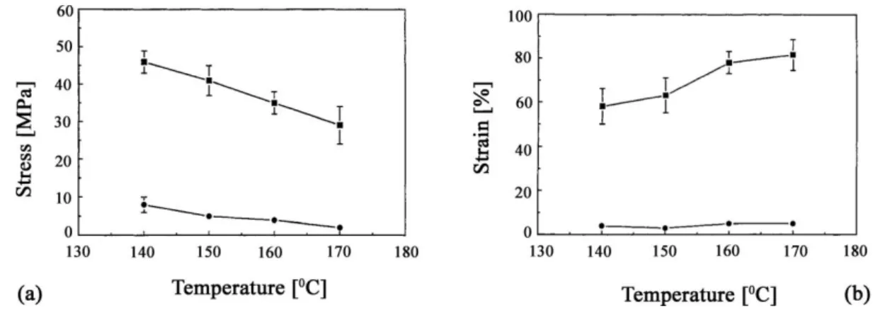
McKown and Cantwell [75] studied the strain-rate sensitivity of a hot-compacted, self- reinforced PP composite. The SRPP specimens were subjected to strain rates ranging from 10−4 to 10 s−1. The SRPP composite showed similar characteristics to the neat PP material in respect to the stress–strain behaviour with increasing strain rate. Stiffening of the material in the elastic region was followed by enhanced yield stress and maximum stress with increasing strain rate. Parallel to that, the strain-to-failure was reduced. The failure mode of the SRPP composite was characterized by longitudinal fibre fracture with varying degree of inter-ply delamination over the dynamic tensile loading range studied. Prosser et al. [76] investigated the thermoformability of hot compacted PP sheets with 2D reinforcement (woven fabric). It was reported that the self-reinforced PP sheets experienced considerable work hardening, according to in-plane tensile tests performed at high temperatures (cf. Figure 9).
26
Figure 9. Effects of testing temperature on the stress-strain behaviour of self-reinforced PP with 2D reinforcement, schematically. (a) dependence of yield stress (●) and failure stress (■) on test temperature
(b) Dependence of yield strain (●) and failure strain (■) on test temperature [76]
The authors observed that the optimum thermoforming temperature is very close to that of the melting of the matrix formed by recrystallization of the melted part of the parent fibre/tape. Romhány et al. [77] studied the fracture and failure behaviour of woven fabric- reinforced self-reinforced PP (Curv®), making use of mechanical fracture concepts and recording the acoustic emission during the loading of the specimens. The latter technique proved to be well suited to characterize the consolidation quality. Jenkins et al. [78] prepared a range of flat hot-compacted single-polymer composite panels from oriented PP and PE. The panels differed in their dynamic modulus and damping capacity values. SRPMs were subjected to mechanical excitation, allowing their acoustic frequency responses over the audio bandwidth to be measured. The results showed the correlation of mechanical and acoustic frequency response functions with the dynamic modulus, damping and specific modulus of the panel materials. The ideal combination of material properties to maximize the acoustic output of the panels was given by: high stiffness and low density to reduce the impedance of the panel and low damping to enhance the efficiency. One major goal of the hot compaction technology was to offer lightweight and easily recyclable thermoplastic composites to the transportation sector. As further application fields, sporting goods, safety helmets, covers and shells (also for luggage) were identified. Hot compacted PP sheets from woven PP fabrics are marketed under the trade name of Curv® (www.curvonline.com). As mentioned before, the hot compaction method was successfully transferred to many other polymers, like multifilament assemblies of PET and PEN [55, 79], PA-6.6 [59], POM and PPS [54], PEEK [54] and even PMMA [62]. Needless to say, the optimum compaction conditions are strongly material-dependent.
27 2.1.2.7. Production by film stacking
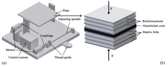
During film stacking, the reinforcing layers are sandwiched in-between the matrix- giving film layers before the whole ―package‖ is subjected to hot pressing. Under heat and pressure, the matrix-giving material, that has a lower melting temperature than the reinforcement, melts and infiltrates the reinforcing structure accordingly. Recall that both the matrix and the reinforcement are given by the same polymer or polymer family. The film stacking procedure is highlighted in Figure 10.
Figure 10. Scheme of the composite processing via film stacking [3]
The necessary difference in the melting temperatures between the matrix and the reinforcement can be set by using different polymer grades (e.g. copolymers for the matrix and homopolymers for the reinforcement, which per definition belongs to the multi- component SRPMs) or polymorphs (e.g. lower melting modification for the matrix and higher melting one for the reinforcement; this concept yields a single-component SRPM). It is of great importance to have a large enough difference between the melting temperatures of the composite constituents. Accordingly, the matrix-forming grade melts and wets out of the reinforcing structure without causing a temperature induced degradation in the stiffness and strength of the reinforcement, or at least keeping it at an acceptable level. Those thermoplastic systems, which can be used to produce single- and multi-component SRPMs via film stacking, are summarized in Table 1.
28
Table 1. Possible polymer pairs to produce SRPMs; * single component SRPM; x production occurs via liquid composite moulding [3]
In the follow-up section, we shall treat only the single component SRPM versions.
Bárány et al. [80-83] produced different PP-based SRPMs. For reinforcement, highly oriented fibres in different textile architectures (carded mat, carded and needle-punched mat, in-laid fibres in knitted fabrics) were used, whereas for matrices either PP fibres of lower orientation (the same textile assemblies as indicated above) or beta-nucleated PP films were selected.
Note that some of the above preforms do not even contain interleaving films and thus do not fall strictly under the heading of film stacking. The matrix-giving phase in them is either a discontinuous fibre or a knitted fabric. Nevertheless, their consolidation occurs by hot pressing as in the case of film stacking. One consideration is that the melting temperature of the beta-modification of isotactic PP is more than 20°C lower than the usual alpha-form [84].
The beta modification can be achieved by incorporating a selective beta nucleating agent in the PP through melt compounding [85]. The concept of this alpha (reinforcement)/beta (matrix) combination should be credited to Karger-Kocsis [86]. The consolidation quality of the all-PP composites produced by Bárány et al. [87] was mostly studied as a function of processing conditions, viz. temperature. With increasing temperatures, the stiffness and strength increased and the resistance to the out-of-plane-type perforation impact decreases.
The consolidation quality of the layered composite laminates could be well qualified by the interlaminar tear strength. Bárány et al. [81-82] later used PP fabric (woven type from split yarns) as the reinforcement and beta-nucleated PP film as the matrix-giving material. As mentioned above, the benefit of the beta-modification is the widening of the melting temperature range between the reinforcement and the matrix [88]. With increasing processing (pressing) temperature, the consolidation quality was improved. Parallel to that, the density, the tensile and flexural stiffness and the strength increased, whereas the penetration impact
Composite Matrix Reinforcement Processing temperature range
(∆T)
PE LDPE UHMWPE fibre 20-40°C
HDPE UHMWPE fibre 20-40°C
PP
β-PP* highly oriented iPP fibre 20°C
random PP copolymer highly oriented iPP fibre 25°C
iPP* highly oriented iPP fibre 8-10°C
Polyester
PETG PET fibre 40-60°C
PETG PEN fibre 15-20°C
CBTx PBT 60-80°C
LCP LCP LCP (Vectran® M) 25°C
29 resistance diminished. The authors proved by polarized light microscopy the presence of a transcrystalline layer between the PP reinforcement and PP matrix (cf. Figure 11).
Figure 11. Transcrystalline layer of PP fibre and β-rPP matrix [3]
Izer and Bárány [83] manufactured all-PP composites by direct hot pressing of suitable textile assemblies. As indicated above, these assemblies contained both the reinforcement and matrix-giving phases in form of fibres with different orientations (draw ratios). Recall that the latter is the guarantee for a small difference in the melting temperatures, which was used in this case. Abraham et al. [89] produced all-PP composites with tape reinforcement by exploiting the difference in the melting behaviour of alpha and beta-polymorphs. The alpha- PP tapes were arranged in UD and cross-ply (CP) manners by winding, putting beta-nucleated PP films in-between the related reinforcing tape layers. The stiffness as a function of temperature of the corresponding composites was determined by dynamic mechanical thermal analysis (DMTA).
Bhattacharyya et al. [90] prepared an SRPM by combining hot compaction and film stacking. High tenacity PA-6 yarn was used as reinforcement, and PA-6 film (from pellets) was used as matrix. The yarn was subjected to annealing in a vacuum (3 h at 150°C) in order to get a higher melting point. Two yarn layers were sandwiched in between two matrix films and subjected to compression moulding at 200°C for 5 min under a pressure of 15 MPa. With the combination of these two techniques, good wetting properties were achieved and materials with excellent mechanical properties were produced. The tensile modulus and strength of the composites were improved by 200 and 300–400%, respectively, compared to the initial isotropic matrix film. An overview on the production methods, conditions and product characteristics of single-component SRPMs produced in multi-step (ex-situ) processing is given in Appendix Table 6. – cf. Figure 1.
30 2.2. Multi-component SRPMs
SRPMs can also be produced by the combination of polymers that belong to the same family of polymeric materials. The major goal during their preparation is the achievement of good adhesion (bonding) between the reinforcing and matrix-giving polymer phases. Like the single-component SRPMs, the reinforcing structure may be generated in single- (in situ) or multi-step (ex-situ) operations. Accordingly, a similar grouping as before can also be followed here. Next, the different variants will be briefly introduced.
2.2.1. Single-step (in situ) production
2.2.1.1. Multi-component extrusion yielding self-reinforced structures
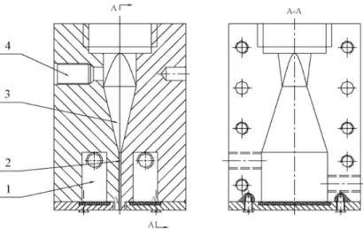
The extrusion die with a convergent section allowed us to set a unidirectional (1D) molecular alignment in situ, which will work as the reinforcement owing to the supermolecular structure formed by the crystallization. Chen et al. [91] solved the problem of biaxial orientation (2D), however, by using a specially designed fish-tail shaped (bi-cuneal shape) extrusion die, as depicted in Figure 12.
Figure 12.Schematic representation of the self-reinforcing sheet extrusion die: (1) temperature controlling oil bath, (2) the straight section, (3), the convergent section, and (4) double functional temperature–
pressure sensor [91]
Composites with planar reinforcement were produced via this die from HDPE and HDPE/UHMWPE blends using a single-screw extruder. The mould temperature was controlled with oil (T = 126–137°C), and the optimum processing pressure was between 15 and 30 MPa. Under conventional extrusion conditions, the tensile strength of the extruded sheet was comparable to conventionally moulded HDPE samples. The tensile strength was
31 almost the same in both the machine (MD) and the transverse directions (TD). The tensile strengths of the HDPE/UHMWPE in the extrusion and transverse directions were six and three times higher, respectively, than those of the related traditionally produced sheet (HDPE).
2.2.1.2. Multi-component SCORIM/OPIM
Zhang et al. [92-93] processed LDPE/HDPE and HDPE/PP blends by the earlier introduced OPIM technique (oscillation frequency: 0.3 Hz). It was established that with increasing LDPE content the tensile strength diminishes, whereas the toughness increases for the LDPE/HDPE blends. Morphological studies confirmed the onset of a shish-kebab-type supermolecular structure. The tensile strength of the HDPE/PP blends could also be markedly increased (fivefold) when the PP content remained below 10 wt%. Zhang et al. [94]
investigated the performance of HDPE/UHMWPE when processed by the SCORIM technique. Tribological tests showed that the wear resistance of the related system was ca.
50% better than that of traditionally molded specimens. Appendix Table 7 displays the production methods, conditions and product characteristics of multi-component SRPMs produced in single-step (in situ) processing - cf. Figure 1.
2.2.2. Multi-step production
The first publication of this processing version should be credited to Capiati and Porter [95]. They combined HDPEs with different melting characteristics. The high modulus fibres (reinforcement) melted at 140°C, while the matrix-giving HDPE melted at 131°C. The HDPE fibre was embedded in the melted HDPE using a special rheometer. After cooling/solidification, the fibre in this single-fibre reinforced composite was subjected to a pull-out test. It was reported that the interfacial shear strength was comparable with that of the glass fibre/epoxy system. Moreover, the presence of a transcrystalline layer was detected at the fibre/matrix surface.
2.2.2.1. Consolidation of coextruded tapes
The development of SRPMs is best reflected by searching for options that amplify the difference between the melting of the reinforcement and the matrix. Recall that this range was highly limited for hot compaction. Peijs [96] developed a coextrusion technique for which the melting temperature difference between the composite constituents reached 20–30°C. The invention was to ―coat‖ a PP homopolymer tape from both sides by a copolymer through a
32 continuous coextrusion process. Note that a copolymer melts always at lower temperatures than the corresponding homopolymer, owing to its less regular molecular structure. The coextruded tape was stretched additionally in two-steps (cf. Figure 13).
Figure 13. Co-extrusion technology with additional stretching to produce high-strength tapes [97]
This resulted in high-modulus, high-strength tapes. The primary tapes could be assembled in different ways: as in composite laminates (ply-by-ply structures with different tape orientations, such as UD (cf. Figure 14) and CP) or integrated in various textile structures (e.g. woven fabrics).
Figure 14. Production of composites with UD tape alignment from coextruded tapes [3]
The consolidation of the related assemblies occurred by hot pressing. The advantage of this method is that the reinforcement (core) content of the tape may be as high as ca. 80%.
This, along with the high draw ratio, yielded tapes of excellent mechanical properties (E- modulus > 6 GPa, tensile strength > 200 MPa). Cabrera et al. [98] prepared all-PP composites from UD and woven fabric assemblies of coextruded tapes. For the consolidation of the UD composites, a 17 MPa pressure was used and the temperature covered the range between 140 and 170°C. The time was kept constant (15 min) during hot pressing. The E-modulus of the laminates, measured both in the tape direction and transverse to it, was not much affected by the processing temperature. In contrast, the interlaminar tear strength was improved by
33 increasing the temperature, well reflecting the improvement in the consolidation quality. The woven fabric-reinforced composites were subjected to falling dart (perforation impact) tests.
Based on the related specific (i.e. thickness-related) perforation impact energy data, the all- PP composites outperformed both the glass fibre (GF) mat- (three times higher) and flax mat- reinforced counterparts (six times higher). Alcock et al. [99] manufactured UD composite sheets by winding the coextruded tapes on a metallic frame that was later put in-between the plates of a press operated in the temperature interval of T = 140–160°C.
The properties of the composites were determined in mechanical investigations, whereas the reinforcement content (reaching 90 wt%) was determined via microscopic investigations. As usual, for all UD-reinforced composites, both the tensile E-modulus and strength decreased with increasing angle between the reinforcing and loading directions (off- set) during their testing. The transverse compressive strength (10 MPa) was not affected by the pressing temperature. The results received were compared with those measured on 50 wt% UD GF-reinforced PP composites. Although the UD-GF PP composite performed better than the all-PP material, the latter took the lead with respect to the related specific (i.e.
density-related) properties. In follow-up studies, Alcock et al. [97, 100-103] investigated the structure–property relationships in all-PP composites produced from woven fabrics composed of coextruded tapes. When the consolidation took place at low temperatures (T = 125°C) and under low pressures (p = 0.1 MPa), the sheets exhibited excellent resistance to the perforation impact. This was traced to an intensive delamination between the fabric layers that was triggered during this high-speed perforation process.
Up to a 2 mm sheet thickness, the perforation energy increased linearly with the sheet thickness. Ballistic test results confirmed that the performance of composite sheets from Pure® tape is comparable with that of the state-of-art ballistic materials. The authors draw attention to the fact that the mechanical performance of the all-PP composites, which contain fabrics of coextruded tapes, can be optimized upon request by selecting suitable textile architectures and hot pressing/consolidation parameters (pressure, temperature). Barkoula et al. [104] investigated the fatigue performance of PP tapes and woven tape fabric-reinforced all-PP composites. They found that the endurance limit (or fatigue threshold, below which no fatigue-induced property reduction occurs), controlled by the onset of delimitation, is strongly affected by the processing temperature. The fatigue threshold of the optimum processed composite was at 65% of the static tensile strength. This is markedly higher than that of GF mat-reinforced PP composites, which show a range of 30–40% [105]. Banik et al. [106-107]
34 studied the short-term creep performance of coextruded tape-reinforced PP composites with both UD- and CP-type tape lay-ups. The related sheets were produced by vacuum bagging in an autoclave (which is almost exclusively used for thermoset composite production) under a 2.4 MPa pressure and at T = 138°C. The flexural creep tests were performed in a DMTA device in the temperature range of 20–80°C. It was reported that the creep depends on the composite lay-up. By adopting the temperature-time superposition principle to the short-term creep results, a master curve was constructed that predicted the long-term creep at a given temperature.
Kim et al. [108] also studied the creep response of all-PP composites and emphasized that small changes in the processing conditions have a pronounced effect on the creep behaviour. It is noteworthy that composites from coextruded PP tapes in different assemblies were produced by various techniques, such as hot pressing, tape winding [109], stamp forming and vacuum bag/autoclaving [110-111]. Moreover, the related sheets were used for the face-covering of different sandwich structures with cores including honeycomb structures and foams. The face sheeting occurred with or without additional primer [112]. Recall that the coextruded PP tapes are known under the trade names of Pure® and Armordon® (www.purecomposites.com; www.armordon.com).
2.2.2.2. Film stacking
This technique is usually used for SRPMs in which the constituents are from the same polymer family. Shalom et al. [113] produced high-strength PE fibre- (Spectra®) reinforced HDPE composites by winding the fibre in a unidirectional manner and sandwiching the HDPE films in-between the wound fibre layers. The reinforcing fibre content in the UD assembly was 80 wt%. Its consolidation occurred by hot pressing (T = 137°C, p = 16.5 MPa).
Samples were subjected to tensile tests with variation of the loading direction in respect to the UD fibre alignment (off-axis tests). As expected, the tensile modulus, yield stress and resistance to fracture were all higher when the off-axis angle was smaller. Houshyar and Shanks [114] used a mat from PP homopolymer fibres as the reinforcement (fixed at 50 wt%) and PP copolymer film as the matrix-giving material. The difference in their melting temperatures was ca. 16°C according to DSC results. The fibre diameter in the mat was varied. The hot consolidation occurred between 155 and 160°C. It was found that with increasing diameter of the mat fibres, both the stiffness and the strength of the composites increased. The surface of the homopolymer PP fibre acted as a heterogeneous nucleator and initiated transcrystalline growth. In follow-up studies [115-116], it was demonstrated that
![Figure 2. Scheme of the 1D supermolecular structure formation in a die with a convergent section during extrusion moulding [3]](https://thumb-eu.123doks.com/thumbv2/9dokorg/1309920.105403/13.892.180.713.513.802/figure-scheme-supermolecular-structure-formation-convergent-extrusion-moulding.webp)
![Table 1. Possible polymer pairs to produce SRPMs; * single component SRPM; x production occurs via liquid composite moulding [3]](https://thumb-eu.123doks.com/thumbv2/9dokorg/1309920.105403/28.892.103.776.104.373/table-possible-polymer-produce-component-production-composite-moulding.webp)
![Figure 13. Co-extrusion technology with additional stretching to produce high-strength tapes [97]](https://thumb-eu.123doks.com/thumbv2/9dokorg/1309920.105403/32.892.185.738.213.445/figure-extrusion-technology-additional-stretching-produce-strength-tapes.webp)