KFKI-74-вО
V
L. K O V A C J, B A L L A
C O M B I N E D H e 3 C R Y O S T A T S
A N D Н е 3 - Н е Ч D I L U T I O N R E F R I G E R A T O R S
Зхмщ гт ап SAcadenut of Sciences
CENTRAL RESEARCH
INSTITUTE FOR PHYSICS
BUDAPEST
t
COMBINED He3 CRYOSTATS AND Не 3 -Не 4 D ILUTION REFRIGERATORS
I). Koväc
P.J. Safárik University, KoSice, Czechoslovakia J. Balia
Central Research Institute for Physics, Budapest, Hungary Solid State Physics Department
physics research, at the Central Research Institute for Physics in Budapest is described. The He4 Dewar and the connected systems are able to accommodate two different interchangable types of inserts, should there be a need to switch from a H e 3 evaporation system to a dilution refrigerator or vice versa.
РЕЗЮМЕ
Производится описание созданной в ЦИФИ комбинированной установки, которая представляет собой Н е 3 испаритель и систему с раствором НеЗ-Не4 . Установка может быть применима для низкотемпературных исследований физики твердого тела в диапазоне 0,05 К - 1,5 К, располагает двумя различными охла
дительными элементами, которые могут быть заменены в зависимости от того, что в данном случае требуется ли эксплуатация Не3 испарителя, или же системы с раствором Н е 3-Не4 .
KIVONAT
о з 4 ~ +
Egy kombinált Не elpárologtató vagy Не -Не oldásos hütoberendezest ismertetünk, amely a KFKI-ban készült. Nagyon alacsony hőmérsékletű szilárd
testfizikai kutatásokra 0,05 К - 1,5 К tartományban alkalmazható, két külön-^
bözS hütőbetéttel, amelyek cserélhetők, attól függően, hogy He3 elpárologtató vagy He3-He4 oldásos rendszert kívánunk-e működtetni.
with large rotary pumps; lower temperatures are difficult to obtain due to 4
the very low vapour pressure of He and the presence of the X transition and the resulting superfluid.
The helium isotope of mass 3 has a considerably higher vapour pres
sure as can be seen in Fig. 1, with no X transition in the discüssed region 3
so b y pumping on the liquid He it is fairly easy to reach temperatures as low as 0.3 К [l,2,3].
The cooling power of this type of cryostat decreases exponentially with temperature making tasks at lower temperatures extremely difficult.
One solution is to apply another process: that of dilution refrigera-
3 4
tion. The dilution of He in He enables temperatures as low as 10 mK to be maintained continuously even with a relatively large heat leak. However, devices capable of this are rather complicated [7]. Simple dilution refrigera
tors can easily reach 50 mK with large heat leaks and give a cooling power over 10 yw at 100 mK [8] .
3 Cooling in the dilution refrigerator is produced by causing the He atoms from the upper almost pure He3 - concentrated phase, to move across the phase separation boundary into the lower dilute, superfluid phase. For de
tailed principles of dilution refrigeration see Ref. [4-73-
It is apparent /Fig. 2/ that the greatest cooling power from 1.5 К О
to 0.4 К can be reached with a He cryostat lower down the scale by a dilu- tion refrigerator. Both the He cryostat and dilution refrigerator in Fig. 2 are pumped with a system able to handle ъ 30 lit/sec of gas in the appropriate pressure range.
For this reason we have designed a modular set of equipment which consists of a He4 Dewar vessel with a very low evaporation rate, having a pumped H e 4 bath in which either a He^ cryostat or a dilution refrigerator within removable inserts can be placed. Any of them can be simply and rapidly
4 3 . 3 4
connected to the versatile Dewar, auxiliary He -, vacuum; and He and He -He systems.
Two such sets have already been completed and can be used at temper
atures from 1.5 К to 0.05 К for thermodynamic and neutron diffraction meas
urements. They have been constructed on the basis of the experience gained at building a H e 3 cryostat [з ] and a dilution refrigerator at the P.J. Safarik University, KoSice and a dilution refrigerator in Budapest [9] .
A . DESCRIP TION OF THE DESIGN
The equipment is based on a He Dewar vessel with a pumped helium 4 bath. Into this bath kept at ^ 1.2 К is immersed the chosen insert with either a H e 3 cryostat or a dilution refrigerator built into the vacuum jacket sus
pended on the pumping tubes. The Dewar as well as the chosen insert are con
nected to the same versatile auxiliary room temperature .systems described in section A 3.
A. 1 , CONSTRUCTION OF THE H e 3 CRYOSTAT INSERT
The inner parts of the He3 insert are shown in Figure 3.
He3 gas is led in and condensed in tube I and is pumped from tube II.
3 3
The small diameter tube I can be used during the He pumping for He vapour pressure measurements and thus for temperature determination /Fig. 5/ /М6 and M 7 /. Pumping line III is connected to a high vacuum system to control the pressure in vacuum jacket provided with an exchange gas inlet. The wires to thermometers and heaters are also led through this tube if necessary. Both the He and the vacuum pumping lines are furnished with light radiation traps; the pumping lines are made of thin-walled stainless steel tubes and expand in diameter with rising temperature; the He3 pumping line from 12 mm in liquid He to 32 mm at the top of the Dewar; the vacuum line from 8 mm to 20 mm.
The vacuum jacket /6/ is removable, sealed with an indium "0"-ring.
The condenser /1/ made of the inlet CuNi tube, 2.5 mm i.d. in form of spiral, is over the upper flange of the jacket.
The evaporation chamber /3/ is made of copper; the bottom is machined so as to enlarge the surface in contact with liquid He . The samples can be connected into one threaded boring M10 and four others M4 in the lower end of the chamber. In this cold finger /5/ are the grooves providing the thermal anchoring of wires led to thermometers and heaters and a boring for the thermometer /4/.
Cryostat No I is provided with a 12.5 cm HeJ evaporation chamber cryostat No II with one of 15 cm^.
A . 2 . CONSTRUCTION OF THE D I L U T I ON REFRIGERATOR INSERT
The inner parts of this are shown in Fig. 4.
It is of a simple design placed in a removable vacuum jacket /11/
sealed with indium. On the upper side of the mounting flange are the pumping ports II and III and a condenser /1/ made of a 0.8 mm i.d. 20 cm long copper tube, wound in a spiral, connected to the He^ input line made of a 1 mm i.d.
thin-walled CuNi tube. A flow impedance /2/ is located at the output of the -3 3 -1
condenser, under the flange. Its value was set to 6x10 cm sec STP N 2 gas flow at room temperature and a pressure drop of ^ 200 torr.
The still /3/ is copper; the orifice in its top, to reduce the He4
3 3
film flow is 1 mm in diameter. The still has a volume 9 cm in No I and 12 cm in dilution refrigerator No II.
No. II is constructed to enable step-heat exchangers to be accommo
dated but they have not as yet been fitted.
Within the still is the still exchanger /4/ made of a copper 0.8 mm i.d. tube 100 cm long. The heater /5/ "v 600 ohms is wound on the outer surface of the bottom of the still, where a thermometer /9/ is also placed.
The coaxial counterflow heat exchanger /6/ is made of two thin-walled CuNi tubes, the inner one having a 0.25 mm i.d., the outer one 1 mm i.d. They are both bent into a spiral together. The heat exchanger for No. I is 120 cm long; that for No II, 90 cm long. There is a copper strip thermal ground at the colder 1/3 of the spiral.
The 4 cm volume copper mixing chamber /7/ is fixed on a very thin 3 walled stainless steel support tube. The lower bottom of the mixing chamber is machined on the inside so as to enlarge the surface in contact with liquid.
The cold finger /8/ is of the same design as those on the He cryostats /Fig.3/.
There are also the grooves for thermal anchoring and the thermometer /10/.
The He^ from the still is pumped off through II and the vacuum in the jacket is controlled and monitored via III.
The pumping lines II and III are provided with light radiation traps and are made of thin walled stainless steel tubes widening in diameter. For the He^ pumping line the diameter expands from 12 mm at He temperatures to
45 mm at the top of the Dewar; for the vacuum line from 8 mm to 20 mm. The thermometer and heater wires also are connected via III. This has the advan
tage of room temperature vacuum titjht lead-throughs.
A I 3 , THE ROOM TEMPERATURE SYSTEMS
The Dewar vessel with the chosen insert with fast dismountable joints is connected to auxiliary room temperature laboratory vacuum and plumbing systems shown in Fig. 5 which consist of
4
a / He pumping and recovery system,
b/ high vacuum system - to maintain and monitor the isolation vacuum in the vacuum jacket. There is a valve for letting exchange gas into the vacuum jacket if necessary,
3 4
с/ He and He mixture pumping, circulation, storage and handling system.
In this the He^ and gas mixture storage tanks are of 15 1 volume each.
The room temperature pumping lines are 50 mm i.d. The pumping or circula
tion is facilitated by an Edward's Mercury Diffusion pump 35 1/sec; its pumping rate with a liquid N_ trap is lower, roughly 30 1/sec; and an
^ 3 Alcatel's sealed rotary pump 2 m /hour.
It is to be noted here that if it appears necessary to switch re- 3
peatedly the operation from He system to dilution refrigeration and vice versa, we recommend the provision of an additional storage tank, to save the He^
trapped in rotary pump HEP 1 /Fig. 5/.
B , PERFORMANCE
B . l . HE3 CRYOSTATS
Two inserts belonging to two different sets were examined. The cool
ing down diagram for both is the same and is shown in Fig. 6 compared with that of the dilution refrigerator. The downward part from point 3 of the He cryostat cooling down curve shows two parts; the upper corresponding to the He^ evaporation chamber pumped with rotary pump only, the lower temperature region down to 270 mK being reached by the whole pumping capacity of the system. The cooling power is shown in Fig. 7. Comparison with the cooling power of the dilution refrigerator is in Fig. 2.
Note: the condensation can be completed in approximately 5 minutes, and any temperature within the given range, even the lowest, can be reached in less than 12 minutes. The pumping rate can be controlled by a special v a l v e .
As the existing heat leaks are small, the charged liquid He3 and the He in the pumped path allow at least 8 hours operation without refill.
The lowest temperature in qryostat No. I was 290 mK, that in cryostat No. II 270 mK, due to the differing heat leaks.
Temperatures are derived from the resistance of Speer 220 Ohm
1002 Grade carbon resistors calibrated in 3 points against HeJ vapour pres- sure and He vapour pressure.4
An a.c. resistance bridge was used to measure the resistance of the thermometers. The bridge accuracy is 1%, the power dissipation less than 10-12 W.
В 12■ D I L U T I ON REFRIGERATORS
Insert No.I was examined only.
The cooling down diagram, can be seen in Fig. 6; the resulting cool
ing power is shown in Fig. 8. Comparison with He3 cryostats in Fig. 2 shows only the curve for the greatest cooling power available in the dilution ref
rigerator.
The condensation time can be reduced if the condensation is also led through the pumping line.
The lowest temperature was 50 mK with circulation 1.7x10 ^ moles/sec This corresponds to 0.21 mW still power.
The largest circulation was 1.3x10 ^ moles/sec, which corresponds to 5.4 mW still power and to a full heat load supplied to the mixing chamber at 300 mK.
The temperatures are derived from the resistance of 220 ohm Speer resistors placed in borings in the cold fingers of the mixing chambers. The
3 4
thermometers were calibrated against He and He vapour pressure.
CONCLUSIONS
The performance of all inserts was stable and reliable, differences between the cryostats and runs were small - nearly all within the accuracy of temperature determination. The construction of a lot of parts is identical, allowing rapid manufacture. Assembling and repairs are simple, all parts are easily accessible.
It therefore appears that a favourable piece of laboratory equipment has been designed, manufactjured and tested giving satisfactory results which are in good agreement with those published elsewhere.
REFERENCES
[lj F.E. Hoare, L.C. Jackson, N. Kürti: Experimental Cryophysics, Butterworths London, 1961, 284
[2] R.P. Conte, T. Kitchens, T. Oversluizen: Cryogenics £, 138 /1972/
[3] L. Kovac, S. János, A. Greser, Czechoslovak Journal of Phys. A 2 2 , 20-21 /1972/
[4] B.S. Neganov, N. Borisov, M. Liburg: ZETF 50, 1445 /1966/
[5] J.C. Wheatley, O.E. Vilches, W.R. Abel: Physics £, 1 /1968/
[6] J.C. Wheatley, R.E. Rapp, R.T. Johnson: Journal of Low Temp. Phys.
4, 1 /1971/
[7] W.J. Huiskamp, O.V. Lounasmaa: Rep. Prog. Phys. j36 , 423-496 /1973/
[8] A.C. Anderson: Rev. Sc. I 41^, 1446 /1970/
[9] L. Kovac, J. Balia, Central Research Institute for Physics, Preprint No. KFKI-74-39 /1974/
Fig. 4
Fig. 5
Fig. 6
Fig. 7 Fig. 8
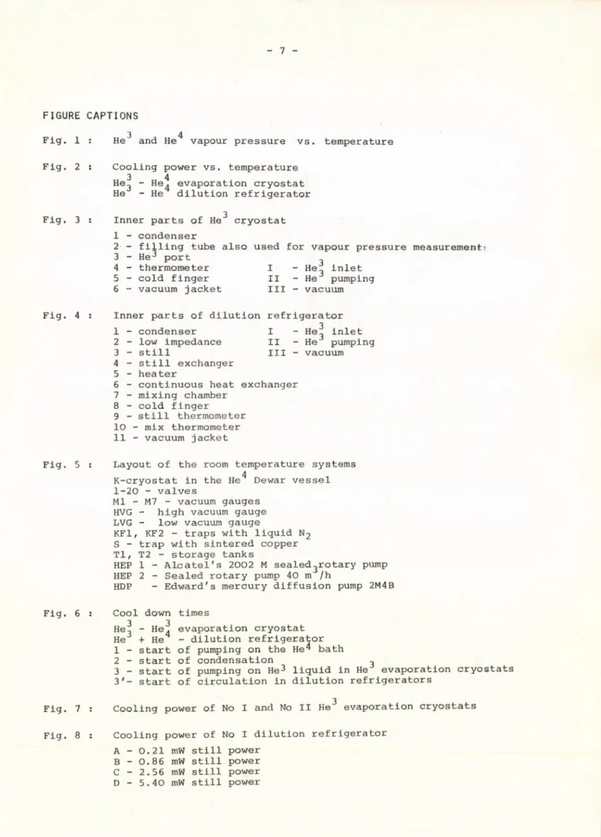
FIGURE CAPTIONS
3 4
Fig. 1 : He and He vapour pressure vs. temperature Fig. 2 s Cooling power vs. temperature
3 4
He3 - He^ evaporation cryostat He - He dilution refrigerator Fig. 3 s Inner parts of He cryostat3
1 - condenser
2 — filling tube also used for vapour pressure measurement!
3 - He3 port
4 - thermometer I - Hef inlet 5 - cold finger II - H e J pumping 6 - vacuum jacket III - vacuum Inner parts of dilution refrigerator 1 - condenser I - He^ inlet 2 - low impedance II - H e 3 pumping
3 - still III - vacuum
4 - still exchanger 5 - heater
6 - continuous heat exchanger 7 - mixing chamber
8 - cold finger
9 - still thermometer 10 - mix thermometer 11 - vacuum jacket
Layout of the room temperature systems K-cryostat in the He Dewar vessel4 1-20 - valves
Ml - M7 - vacuum gauges HVG - high vacuum gauge LVG - low vacuum gauge
K F 1 , KF2 - traps with liquid N 2 S - trap with sintered copper TI, T2 - storage tanks
HEP 1 - Alcatel's 2002 M sealed3rotary pump HEP 2 - Sealed rotary pump 40 m /h
HDP - Edward's mercury diffusion pump 2M4B Cool down times
3 3
He, - He. evaporation cryostat He3 + He4 - dilution refrigerator 1 - start of pumping on the He^ bath 2 - start of condensation ,
3 - start of pumping on He3 liquid in He evaporation cryostats 3'- start of circulation in dilution refrigerators
3
Cooling power of No I and No II He evaporation cryostats Cooling power of No I dilution refrigerator
A - 0.21 m W still power В - 0.86 mW still power C - 2.56 m W still power D - 5.40 mW still power
TEMPERATURE, [ m K ]
FI G 2
i
J
5
6
f
F I G 3
f
F I G . 5
T E M P E R A T U R E ,
30 60 90 120 150
TIM E , [m in ]
F I G 6
I
C O O L IN G P O W E R , [m
FIG 7
C O O L IN G P O W E R ,
[jTEMPERATURE, [ m K ]
FI G 8
f
elnöke
Szakmai lektor: Krén Emil Nyelvi lektor : H. Shenker
Példányszám: 290 Törzsszám: 74-10.174 Készült a KFKI sokszorosító üzemében Budapest, 1974. julius hó