The Dynamic Study of the Weft Insertion of Air Jet Weaving Machines
Lóránt Szabó, István Patkó, Gabriella Oroszlány
Rejtő Sándor Faculty of Light Industry and Environmental Protection Engineering, Óbuda University, Hungary
E-mail: szabo.lorant@rkk.uni-obuda.hu, patko@uni-obuda.hu, oroszlany.gabriella@rkk.uni-obuda.hu
Abstract: The application of the air jet loom is widespread in the textile industry because of its high productivity, convenient controllability, high filling insertion rate, low noise and low vibration levels. Air stream in confusor guides can be classified into two types. A weft yarn ejected with high speed air flow is given the drag force caused by friction between the weft yarn and the air flow. In this article we show the study of the dynamics of the type P air jet weaving machines and the definition of the skin friction coefficient for multifilament weft. We have given a calculation procedure for the dynamic description of the insertion process of weaving machines marked P.
Keywords: air jet weft insertion; confusor air guides; maintained air jet; fiction force; skin friction coefficient; friction force measurement; momentum; multifilament weft yarn
1 Introduction
In air jet weaving machines weft is accelerated and taken through the shed by the flow impedance between the flowing air and the weft. Air jet weaving machines belong to the set of intermittent-operation weaving machines. The energy resulting from air pressure directed from the central air tank to the weaving machine changes into kinetic energy in the nozzle, which accelerates and delivers the weft in the air channels differently shaped by machine types. The air leaving the nozzle mixes with the still air, it disperses, and the speed of the axis of the flow drops quickly as it moves away from the nozzle; therefore, in order to reach bigger reed width, the air speed must be kept up in the line of the weft course [3].
Three different systems have mainly been used on commercial air jet weaving machines [6]:
• single nozzle with confusor guides,
• multiple nozzles with guides,
• multiple (relay) nozzles with tunnel reed.
Svaty (former Czechoslovakia) patented the confusor drop wires to guide the air in 1949, which resulted in a wide spread of air jet weaving machines marked P. In 1979 the Nissan company started to use plastic confusor air guides closing at the top. Since the 1980s weaving machines with tunnel reeds and relay nozzles have been the focus of developments [4].
On type P air jet weaving machines, the local transonics speed of the air exiting the nozzle speeds up the weft to v=30−40ms-1. By maintaining the velocity of the air jet along the reed width, high weft insertion speeds may be reached. We discussed the aerohydrodynamic study of air jet implementing the weft insertion in our articles [1] and [7]. We use the results of our aerohydrodynamic studies in this article.
2 The Relationship and Definition of the Force Applying to the Weft Inserted in the Air Stream and the Friction Force
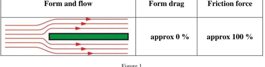
Resistance force is formed on the surface of the body placed into the flowing air due to the effect of the flowing air. This force has two components [5]:
• form drag,
• friction force.
Figure 1 shows the ratio of resistance forces applied to the weft as a result of the relationship between the form and the flow.
Figure 1
The ratio of form drag and friction force in the case of weft
The friction force derives from the viscous shearing, which is created between the body surface and the boundary layer of the flowing medium. In general the ele- mental friction force applying to the elemental surface of the weft may be deter- mined on the basis of the following relationship:
dA c
dF
f=
f⋅ τ ⋅
(2.1)Form and flow Form drag Friction force
approx 0 % approx 100 %
where:
dF
f: elemental friction force; [N],c
f : skin friction coefficient; [-],τ
: shear stress derived from the speed of the flowing medium; [Nm
−2], dA: circumfluent surface element; [m2].The quantity of the surface element with diameter D and elemental length dx in case of thread:
dx D
dA
= ⋅ π ⋅
(2.2)The shear stress originating between the moving weft and the air jet is given on the base of Bernoulli’s equation (Figure 2):
( )
22
1 ⋅ ⋅ u − v
= ρ
τ
(2.3)where:
ρ
: density of flowing air; [kgm
−3], u: flow speed of air; [ms
−1],:
v speed of weft; [
ms
−1].Figure 2
Force acting on a moving weft in air flow [5]
Our studies were made for motionless weft (v
= 0
); therefore we get the follow- ing for shear stress:2
2 1 ⋅ ⋅ u
= ρ
τ
(2.4)We get the elementary friction force by substituting equations (2.2) and (2.4) into relation (2.1):
dx D u c
dF
f= ⋅
f⋅ ρ ⋅
2⋅ ⋅ π ⋅ 2
1
(2.5)Integrating both sides of equation (2.5) on the length L:
dx u D c
F
L f
f
= ⋅ ⋅ ⋅ ⋅ ∫
0 2
2
1 ρ π
(2.6)Considering that the speed of air u is constant on the whole length L:
A f
f c u D L
F
= ⋅ ⋅ ρ ⋅
2⋅ ⋅ π ⋅ 2
1
(2.7)where:
:
D diameter of weft; [m],
:
L length of weft along the reed width; [m],
:
A surface of weft under the impact of the air; A
=
D⋅ π ⋅
L [m2].With a knowledge of the surface of the weft laid in the air stream of length L as well as the force applying to it, the skin friction coefficient may be defined as follows on the basis of equation (2.7):
2
2 u A c
fF
f⋅
⋅
= ⋅
ρ
(2.8)If we know the air speed (u), the friction force (
F
f)
applying to the motionless weft of length dx may be determined from measuring the two forces (Figure 3):F
1F
F
f=
n−
(2.9)where:
1
:
F the force measured at measuring point 1; [N],
n
:
F
the force measured at measuring points n = 2, 3, 4, … 7, 8; [N].The friction force depends on the structure and surface of the weft yarn; these characteristics may be taken into consideration in the skin friction coefficient.
The force applying to a given length of weft may be measured in an air stream of constant speed. For this purpose we have developed the measuring system shown in Figure 3, which consists of a glass tube of inner diameter (Dtube=7mm)con-
nected to the nozzle. We made the speed measurements with a U-tube manometer connected to a Prandtl’s tube placed at the end of a glass tube, assuming that in the case of a tube, the speed of the air stream is constant in the axis of the stream.
The weft enters the glass tube through the nozzle needle with tight cross section situated inside the nozzle. It is important that the weft should not get in contact with the side wall of the glass tube during the measurement, which can be checked visually.
Figure 3
The layout of measuring the skin friction coefficient
The diameter of the weft was determined by a microscope. By averaging multiple measurements, the diameter of the 80 tex multifilament weft wasD=6.34⋅10−4m.
The initial force (F1) came from the friction force applying to the weft fixed at measuring point 1. By directing the weft in the glass tube to the measuring point, fixed in all cases, there were forces (
F
n) corresponding to the measuring points.From equations (2.9) and (2.8) we calculated the different values of skin friction coefficient.
Figure 4 shows the relationship between the skin friction coefficient (
c
f ) and constant air speeds at u = 50, 81.6 and 135.4 ms−1 values in the case of different lengths multifilament weft. It can be seen from the figure that the skin friction coefficient is dependent on the air speed but independent of the inserted weft length.The purpose of our further examinations was to determine the
⎟⎟ ⎠
⎜⎜ ⎞
⎝
= ⎛
u0f u cf
relation for an 80 tex multifilament weft. The measurements were done in the ms-1
3 . 174 30−
=
u flow speed range and skin friction coefficients were deter- mined here.
Figure 4
At different air speeds the variation in the skin friction coefficient – in case of constant air speeds – as a function of x
First the initial force F1 was measured in measuring point 1, then the end of the weft was fixed according to measuring point 8, and force
F
8 was measured at the air speed belonging to the previous measuring point (Figure 3). We obtained the friction force applying to the weft of x=640mmin length:1
8
F
F
F
f= −
(2.10)By applying equations (2.10) and (2.8) we obtained the results of Table 1 for skin friction coefficients for a multifilament (80 tex) weft.
Table 1
The values of skin friction coefficient at different speeds Air speed:
u [m/s]
Undimensioned speed:
⎟⎟⎠
⎜⎜ ⎞
⎝
⎛ u0
u [-]
Friction force:
F
f[⋅10−2 N]
Skin friction coef- ficient:
c
f [-]30 0.17 1.5 0.022
39 0.22 2.25 0.019
50 0.28 3.4 0.0118
63 0.36 4.5 0.015
76.3 0.43 5.5 0.0127 81.6 0.47 5.75 0.0113 100 0.57 9 0.011 115.4 0.66 11 0.0108 135.4 0.77 12 0.0086 150 0.86 13 0.0076
3 .
0=174
u 1.0 15 0.0074
The
u
0 (at pt =3bartank pressure) is the maximum air speed exiting the noz- zle. If we use the results from Table 1 and if we un-dimension the air speed byu
0, we get the function shown in Figure 5, which shows the values ofc
f as a function of different nondimensional air speeds( u / u
0)
.On the basis of the set of measurement points we used power function approxima- tion to determine function
⎟⎟ ⎠
⎜⎜ ⎞
⎝
= ⎛
u0f u
cf (Figure 5).
Figure 5
The variation of skin friction coefficient in case of power approximation
From Figure 5 we can read the approximation function describing function
⎟⎟ ⎠
⎜⎜ ⎞
⎝
= ⎛
u0f u
cf :
631 . 0 0
0075 . 0
-
f u
c u ⎟⎟⎠
⎜⎜ ⎞
⎝
= ⎛ (2.11)
3 The Dynamic Examination of Weft Moving in Confusor Guides
Weft insertion by air jet is a complicated movement, which is not a fully con- trolled technological process. When the motionless weft threaded in the nozzle gets into the air stream, at the moment of starting the insertion, the weft makes an accelerating move, which is created by the friction force deriving from the relation of the weft and the air. This section of weft insertion (when the speed of weft is
smaller than the speed of air stream) is called the acceleration condition of the weft (Figure 6). The acceleration condition may be divided into two parts:
• intense acceleration section, the initial part after the nozzle pipe; the speed of weft increases abruptly,
• weak acceleration section, in which the speed of the weft increases slowly until it is equivalent with the air speed.
Figure 6
The possibility of modifying the weft speed with air stream from one nozzle maintained by confusor guides
The weft acceleration stoppage is caused by the change in the direction of the friction force, which slows down the weft (
x > x
crit). The weft keeps moving due to its inertia and its speed does not increase any more. Therefore, the ideal situation for air jet machines would be if the reed width were smaller thanx
crit. In order to achieve this, different air guide systems are used to maintain high air speed (and thus high weft speed) along the reed width of the machine. In the case of air jet weaving machines, the force moving the weft is exclusively defined by the drag emerging between the air and the thread. The motive force applying in the direction of insertion increases with the air speed and the diameter of the weft.During weft insertion the elemental friction force applying to the elemental weft section may be determined from equation (2.5) and considering that the weft speed is v
≠ 0
, on the basis of the following equation:dx v u D c
dF
f f( )
22
1 ⋅ ⋅ ⋅ ⋅ −
= ρ π
(3.1)The equilibrium of forces applies to the weft inserted in the air stream:
S
f
F
F dt I
d = −
(3.2)where:
I: momentum of the weft; [
kg ms
-1],F
f : friction force; [N],F
S: force deriving from the friction of the weft and other solid state; [N].During the course of our further examinations we disregard friction force
F
Sbecause the weft removal from the holder and its passage through the guide ring is almost frictionless. Inside the nozzle the relation is generated between the weft and the air stream. Our research only focused on the dynamic study of the weft and air stream exiting the nozzle and moving in different air guide systems. By neglecting friction force (
F
S), the created model is not complete, but it is suitable for studying the force which is generated along the axis of the insertion and which moves the weft [2].In this way we get the differential equation describing the relation between the weft and the air stream inserting the weft on air jet weaving machines marked P:
F
fdt mv I d dt
d = =
(3.3)where:
m: the mass of weft yarn in the air stream; [kg],
v the speed of the weft end at the place of study; [
ms
−1].On the laboratory bench shown in Figure 7 we measured the friction forces apply- ing to the 80 tex multifilament weft inserted in a continuous air stream. The size of the slot distance is shown in the figure:
mm 35 5 ⋅
0=
= d
R
t (3.4)where:
0
:
d
inside diameter of the nozzle at the exit;d
0= 7 mm.
Figure 7
The arrangement of laboratory measurements of forces applying to the weft
Based on our experience it is understood that the friction force applying to the weft depends on:
• the tank pressure used,
• the air guide system,
• the length of the inserted weft in the confusor guides, up to about x = 170 cm,
• the yarn structure and diameter of the weft,
• the yarn surface characteristics.
Afterwards, we examined the relation between the theoretically identifiable fric- tion force applying to the weft and the force applying to the motionless weft in- serted into the continuous air stream. By substituting weft speed v
= 0
into equa- tion (3.1) we regain equation (2.5):In our previous study [1] our aim was to make a function which would define the flow speed at any given point of the reed width for any air guide system, as a func- tion of the initial conditions. In the case of closed plastic drop wires for nondimen- sional velocity distribution ⎟⎟⎠
⎜⎜ ⎞
⎝
⎛ u0
u we obtained the following functional relation- ship:
x c b r r a x
r x
r b c x r a x
u
u
⎟ +
⎠
⎜ ⎞
⎝ + ⎛
⎟⎟ ⎠
⎜⎜ ⎞
⎝
= ⎛
⎟⎟ ⎠
⎜⎜ ⎞
⎝
⎛
⎟⎟ +
⎠
⎜⎜ ⎞
⎝ + ⎛
⎟⎟ ⎠
⎜⎜ ⎞
⎝
⎛
⎟⎟ =
⎠
⎜⎜ ⎞
⎝
⎛
00 0
0 2
0 0
(3.5)
where the constants for closed plastic confusor guides are:
guides.
confusor the
of entrance at the
speed air , ms 3 . 174 u
exit, at the nozzle applied the
of radius mm, 5 . 2 3 r
[-], 0.3243 c
[-], 5.288 b
], [ 0004 . 0
1 0 -
0 0
=
=
=
=
=
−
−
=
d a
Equation (2.5) undimensioned by values
u
0and r
0:⎟⎟ ⎠
⎜⎜ ⎞
⎝
⋅ ⎛
⎟⎟ ⎠
⎜⎜ ⎞
⎝
⋅ ⎛
⋅
⋅
⋅
⋅
⋅
=
0 2
0 0
2
2
01
r d x u c u r u D
dFf
ρ π
f (3.6)Furthermore, considering equation (2.11), substituted in place of
c
f , we get:⎟⎟ ⎠
⎜⎜ ⎞
⎝
⎟⎟ ⎛
⎠
⎜⎜ ⎞
⎝
⋅ ⎛
=
⎟⎟ ⎠
⎜⎜ ⎞
⎝
⋅ ⎛
⎟⎟ ⎠
⎜⎜ ⎞
⎝
⋅ ⎛
⎟⎟ ⎠
⎜⎜ ⎞
⎝
⋅ ⎛
⋅
⋅
⋅
⋅
⋅
=
−
⋅
= −
0 37 . 1
0
0 2
0 631 . 0
0 N
10 95 . 0
0 2 0
3
0075 . 2 0
1
r d x u K u
r d x u
u u
r u u D dF
K
f
ρ π
(3.7)
and in the case of:
m, 10 5 . 3 r
, ms 3 . 174 u
m, 10 6.34 D
, kgm 2 . 1
3 0
1 - 0
4 - -3
⋅
−=
=
⋅
= ρ =
then K =0.95⋅10−3[N]. By substituting
⎟⎟ ⎠
⎜⎜ ⎞
⎝
= ⎛
r0z x , and examining the plastic guides, we can calculate the elemental force applying to the weft yarn with the following equation:
dz z c
z b a K dF
f37 . 1
⎟ ⎠
⎜ ⎞
⎝
⎛ ⋅ + +
⋅
=
(3.8)By integrating both sides of equation (3.8) we get:
dz z c
z b a K dF
z z z
z f
37 . 1
0 0
⎟ ⎠
⎜ ⎞
⎝
⎛ ⋅ + +
∫ ⋅
∫ =
(3.9)that is:
∫ ⎟
⎠
⎜ ⎞
⎝
⎛ ⋅ + +
⋅
=
−
zz f
f
c dz
z z b a K z F z F
0
37 . 1 0
)
( )
(
(3.10)where:
: ) ( z
0F
0F
f=
at x= 0
the measured force applying to the weft at the be- ginning of the air guide system; [N]. On the basis of our meas- urements demonstrated in Figure 7: F0= 2 ⋅ 10
−2N
.: ) ( z F
F
f=
in the case ofx> 0
, the drag applying to the weft in the axis of the confusor guides; [N].By dividing equation (3.10) by value K and by substituting the constants of equa- tion (3.5) into (3.10), we get the undimensioned equation suitable for final integra- tion:
∫ ⎟
⎠
⎜ ⎞
⎝
⎛ − ⋅ + +
+
=
∗∗ z
z
z dz z
F F
0
37 . 1
0
5 . 288 0 , 3243
0004 .
0
(3.11)where:
K :
F
∗= F
the theoretical undimensioned force applying to the weft in air guide system; [-],[ ] [ ] 21 [ ] - :
N 10 95 . 0
N 10 2
3 0 2
0
=
⋅
= ⋅
=
−−∗
K
F F the undimensioned force measured at the
beginning of the air guide system; [-].
We integrated the second member on the right side of equation (3.11) using the program “Maple 13”. Figure 8 demonstrates the graphic solution of equation (3.11).
The figure shows the trend of the measured forces applying to multifilament 80 tex weft placed into continuous air stream in the case of confusor guides compared to the calculated values.
Figure 8
In the case of closed plastic guides, the comparison of the measured and the theoretical values
From the measured and calculated values shown in Figure 8, we determined the deviations in the measuring points (
D
i), which can be found in Table 2.Table 2
The deviation of measured and calculated values as a function of
⎟⎟ ⎠
⎜⎜ ⎞
⎝
⎛
r0x
Measuring
point: i Place:
⎟⎟ ⎠
⎜⎜ ⎞
⎝
⎛
r0x [-]
Measured value:Fmi∗ [-]
Calculated value:Fci∗ [-]
Deviation:
D
i [-]Ratio:
R
i [-]1 14.3 42.1 41.5 0.6 0.985 2 28.6 57.9 54,3 3.6 0.937 3 57.2 68.4 67.5 0.9 0.986 4 85.8 84.2 78.1 6.1 0.927 5 114.4 94.7 84 10.7 0.88 6 171.6 100 94.7 5.3 0.947 7 228.8 105.3 101.5 3.7 0.964 8 286 110.5 108 2.5 0.977 9 343.2 117.1 115.6 1.5 0.987 10 400.4 121 118 3 0.975 11 471.4 121 120 1 0.991 The deviations may be determined from the values in columns 3 and 4 of Table 2:
∗
=
mi∗- F
cii F
D (3.12)
where:
i
:
D
deviation belonging to the measuring point (column 5 in Table 2); [-],∗
:
Fmi measured value; [-],
∗
Fci: calculated value belonging to the measuring point; [-].
We calculate their average from deviation (n
= 11
):= ∑
= n i Di
D n
1
1 (3.13)
where:
:
D
the average of the deviations; in our caseD = 3 . 53
[-].In order to analyze the deviations between the measured and the calculated values we have introduced the ratio:
∗
= ∗ mi
ci
i F
R F (3.14)
where:
i
:
R
ratio belonging to the measuring point (column 6 in Table 2); [-].Similar to equation (3.1) we have determined the average of the ratios. Since the number of our measurements is
n < 30 ,
it is more practical to use the corrected standard deviation instead of the standard deviation:( )
1
1
2
−
∑ −
= =
∗
n R R S
n
i i
(3.15)
where:
∗
:
S corrected standard deviation calculated from the ratios belonging to measuring points; [-], which in our case was 0.0342,
:
R
average of ratios; [-].The value of the corrected standard deviation of the ratios is small. Therefore it may be concluded that the calculated values approximate the measurement results very well. The measured values were bigger at all the measuring points, which may be explained by the fact that the force measuring equipment increased the size of the actual force generated on the weft. The inclusion of the measuring equipment modified the measurement results in a similar manner. This type of error is called systematic error.
Conclusions
Weft insertion through an air stream is a complex and complicated process. The motionless weft threaded in the nozzle gets into the effect of the air stream at the insertion of the weft, as a result of which the weft makes an accelerating move, which is created by the friction force deriving from the contact of the weft and the air. This section of weft insertion is the acceleration section, which may be divided into two parts.
The results of the research:
• We have provided a calculation method for the calculation of air speeds generated in the axis of the different confusor guides: 0
0
r u f x u ⎟⎟⎠⋅
⎜⎜ ⎞
⎝
= ⎛ [1].
• For multifilament 80 tex weft we have determined the function
⎟⎟⎠
⎜⎜ ⎞
⎝
= ⎛ u0
f u
cf describing the skin friction coefficient of the weft
• We have created a calculation method to determine the force applying to the weft thread – after the insertion – by describing functional relationship
⎟⎟⎠
⎜⎜ ⎞
⎝
= ⎛
∗
0 0
;u u r f x
F .
• Having considered the previous points we have given a calculation proce- dure for the aerohydrodynamic and dynamic description of the insertion process of weaving machines marked P.
References
[1] Patkó I., Szabó L.: A szövés és áramlás kapcsolatának vizsgálata légsugaras szövőgépeken. Magyar Textiltechnika LXII. évf. 2009/5, 194-200. o.
[2] Patkó I.: Lamellák közötti áramlás tulajdonságainak meghatározása. Kan- didátusi disszertáció, Budapest, 1994, 74-75. o.
[3] I. Patkó: The Nozzle’s Impact on the Quality of Fabric on the Pneumatic Weaving Machine. Springer, Volume 243, 2009, UK, pp. 583-592
[4] Szabó R.: Szövőgépek. Műszaki Könyvkiadó, Budapest, 1985, 148. o.
[5] S. Adanur: Handbook of Weaving. Lancaster, Pennsylvania, 2001, pp. 189- 191
[6] M. Ishida, A. Okajima, Y. Shimada, T. Kurata, F. Hoshiai: Experiments of Flow of Air Jet Loom with Air Guides Part 1: Characteristics of Flow In- jected into Air Guides. Journal of the Textile Machinery Society of Japan, 1989, Vol. 36, No. 4, pp. 127-128
[7] I. Patkó, L. Szabó: The Study of the flow Conditions of Air Jet Weaving Machines. Proceedings of the 10th International Symposium of Hungarian Researchers, November 12-14, 2009, pp. 391-412