E L E C T R O P N E U M A T I C A N D E L E C T R O - H Y D R A U L I C C O N T R O L
V I C T O R B R O I D A1
French ARCA Regulator Company, Paris, France
In a pneumatic or a hydraulic controller, the deviation of the controlled variable m from the desired value c generally leads to a variation of the control pressure Ρ acting on the control servomotor, partly proportional to this deviation (m — c), partly proportional to its integral, and partly proportional to its first derivative:
P(t) = A[m(t)-c] + B [[m(t)-c]dt + C-™W
dt
If we use the Laplace operator p, this relationship will become no more in the time domain but in the complex variable domain:
P(p) = A[m(p)-c] + *[m(p)-c] + Cp[m(p)-c]
and the overall transfer function of the controller shall be given by:
FK(p) = - ^ - = A + ?+Cp.
m(p)~ c ρ
The coefficients A, Β and C are fully adjustable on the controller and thus correspond to the proportional term, to the integral term and to the derivative term adjustments of a 3-term control.
While the control unit of the controller is generally standardized—as, for instance, in the case of pneumatic controllers, with a control air pressure, in Anglo-Saxon countries, between 3 and 15 psi and, in metric system countries, between 0.2 and 1 kg/cm2 (which is nearly the same) for the maximum variation of the deviation (m — c)—this is not always the case with its measuring unit.
The construction of the latter has, indeed, to be adapted to the nature of the input signal to the controller in the instance of direct measurement by
1 Prof. Ing. Dr. Victor Broida, Consulting engineer to French A R C A Regulator Company, 56, rue de PEglise, Paris, France.
the latter of such controlled variables as static (positive or negative) pres- sures, differential pressures (in flow, level or density control), temperatures, differential temperatures (in moisture control), etc., and it is obvious that this construction is different from case to case, which deprives the controller of the possibility of being fully standardized as a whole. One of the main advantages of an electric measurement of the controlled variable consists in the fact that the variations of the latter—whatever its nature may b e — are always converted into variations of tension or of intensity and that, there- fore, the input to the controller is always of the same nature, regardless of that of the controlled variable itself.
In fact, if we consider as an example two different ways of measuring a temperature: one non-electric (for instance, a gas-filled bulb) and the other electric (for instance, a thermo-sensitive resistance bulb), the first of these sensing elements necessitates the addition in the controller itself of a meas- uring element (for instance, an expandable bellows) in order to transform variations of the controlled temperature into corresponding variations of a force which could be matched against other forces in a controller of the force-balance type.
On the contrary, the second of these sensing devices can be directly inserted into a measuring bridge and thus be directly matched against other resistances or potentiometers for control purposes without necessitat- ing any extra measuring element in the controller itself. Such a thermo- sensitive resistance constitutes alone the whole measuring unit of a controller and it is a sort of very simple electric transmitter of a measured temperature to be controlled.
This fact has probably induced control equipment manufacturers to produce, outside of the conventional direct-measuring pneumatic controllers, some more modern controllers using pneumatic transmitters in which varia- tions of the measured and controlled variable—whatever its nature may be
—are converted (generally, by a force-balance method) into strictly pro- portional variations of an air pressure fed to the input of the controller.
The latter always becomes under these conditions a pressure controller as it always measures at its input a pressure varying between 3 and 15 psi (or 0.2 and 1 kg/cm2) when the measured variable—whatever its nature may be—deflects from its desired value from 0 to its maximum possible deflection. In this way, the controller itself can be fully standardized, only the pneumatic transmitters being different from one case to another, according to the nature of the measured and controlled variable.
D I R E C T P A T H A N D F E E D B A C K P A T H A D J U S T E D P N E U M A T I C C O N T R O L L E R S
T w o different methods of achieving a three-term control in such modern pneumatic controllers provided with pneumatic transmitters are available.
The first, more conventional method consists in operating on the air pressure supplied by the transmitter, i.e. in fact on the measured and controlled variable itself. In this way, the proportional, integral and deri
vative control components are adjusted in the direct path of the closed loop leading from the input to the output of the controller, i.e. from the deviation of the measured air pressure (representing the measured and controlled variable) versus its desired value to the control air pressure;
this way of operating does not necessitate any particular comments as it is obvious that it leads to the desired overall controller transfer function
^(/>)=4T
L=^+-
+C^
m (p) - c ρ
The other—opposite and much less usual method—consists in operating on the feedback path of the closed loop, leading from the output of the controller to its input, i.e. from the control air pressure to the deviation of the measured air pressure from its desired value.
If we call μ(ρ) and β(ρ), respectively, the transfer functions of the control
ler direct and feedback paths, we know that its closed-loop transfer function can be written as
or, by dividing top and bottom by μ(ρ),
ΡΛ(ρ) = 1/(1/μ(ρ)+β(ρ)).
W e also know that, in the limits of the controller passing band, μ(ρ) is fairly higher than β(ρ) and that therefore 1/μ(ρ) can be neglected in regard of β(ρ). W e can therefore write
FR(p)~l/fi(p)
and approximately replace the overall controller transfer function by the inverse of the transfer function of its feedback path alone.
This means in turn that, if we use a derivative feedback having a transfer function of the type β(ρ) = ap, the overall controller transfer function will be approximately of the type FR(p) = 1 /ap and thus correspond to an integral action.
Inversely, this means that if we use an integral feedback having a transfer function of the type β(ρ) = l/bp, the overall controller transfer function will be approximately of the type FR(p) = bp and thus correspond to a derivative action.
The second method of operating on the feedback path of a controller—
which we shall call the "feedback path method" as opposed to the first one consisting in operating on the direct path of this controller which we shall call "direct path method"—necessitates therefore the introduction into this feedback path of a derivative feedback action in order to achieve an integral overall control component and of an integral feedback action in order to achieve a derivative overall control component. A s to the proportional control component, it can of course also be introduced into the feedback path of the controller closed-loop provided its gain will be approximately the inverse of that to be achieved in the overall controller operation.
In fact, some controllers use the direct path method for some of the control components (for instance, the derivative component and the gain or its inverse—the proportional band), while the remaining control com
ponents (for instance, the integral component) are introduced into the feed
back path by means of an appropriate inversed transfer-function feedback action (in the same example, a derivative feedback action). W e shall give an example of a controller using such a direct path-feedback path combined method.
On the contrary, the use of a purely feedback-path method is less frequent;
we shall also give an example ο ia controller using mainly such a feedback path method.
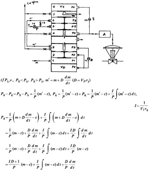
E X A M P L E O F A C O M B I N E D D I R E C T P A T H - F E E D B A C K P A T H A D J U S T E D P N E U M A T I C C O N T R O L L E R The pneumatic controller of Fig. 1 belongs to the combined direct path- feedback path type. It receives in capacity 1 the pressure P1 = m from the transmitter representing the actual measured and controlled variable. If this pressure m increases, the diaphragm between capacities 1 and 2 moves upward and so, too, does the diaphragm between capacities 2 and 3 to which it is connected mechanically.
The upward movement of the latter diaphragm partly covers the outflow nozzle of capacity 3 and, as this capacity is constantly fed with air, pressure Pz also increases and counterbalances the increase of the measured pressure Px = m. However, pressure P2 in capacity 2 increases with a time lag due to the communication between capacities 3 and 2 through an adjustable restric
tion rx combined with a fixed booster capacity VD. In this way, when P1=m and consequently P3 = rri increase, P2 also increases while remaining
2
I
1 PI
Vx> ?z
ι dm
ifPx/> P2<PV P3>PV m=m + D — ( / ) = VDrJ a t
Ρ 4 ~ρβ = ρ 3-Ρ5 = ρ(™ ~c\ P^ = -{m -c) + P% = -{m'-c) + -Um'-c)dt,
1 =
1 / dm \ I Π dm \
P \ dt J p } \ dt J 1 X D C / M
/ Γ
JZ>fi/m
= — + —+ — (m-c)dt+— dt Ρ Ρ dt Ρ J Ρ J dt
1 D dm I C ID
= — (m-c) + — + — (m-c)dt + — (m-c) Ρ Ρ dt Ρ J Ρ
Vir.
lD + \ I Γ Ddm Ρ ( « - c ) + - J ( « - c ) r f r + - —
Fig. 1. Example of a direct-path feedback-path adjusted pneumatic controller.
smaller than P3 and, consequently, Px. In order to ensure a momentary dynamic balance, P3 = ra' has therefore to be greater than P1=m and
rri = m + D(dm/dt),
the coefficient D of the derivative term being proportional to the fixed booster capacity VD and to the adjustable resistance r± of the time-lag circuit between capacities 3 and 2. A s it is seen, the derivative term D(dm/dt) is added to the measured pressure m, i.e. this is done in the direct path of the closed loop.
The pressure rri =m + D(dm/dt) containing the derivative term is lead to capacity 6 and is opposed in capacity 5 by a pressure representing the desired value c of the controlled variable. In fact, a by-pass is provided between capacities 5 and 6 consisting of a fixed restriction r3, and an ad
justable restriction r2 is added to this by-pass.
It is obvious that, if restriction r2 was fully closed, pressures P3 and P5 in capacities 6 and 5 would be equal and their difference equal to zero would be also equal to the difference (mf — c) between the measured pres
sure rri (containing the derivative term) and its desired value c, divided by a coefficient Ρ equal in this case to infinity
P3- P5 = ^ ( m ' - c ) = 0 with -2 = 0 and P= o o .
Ρ r3
On the contrary, if restriction r2 was wide open and supposing the section of restriction r3 relatively negligible versus that of restriction r2, the difference between pressures P3 and P5 would be practically equal to (m' — c) or to the same term (rri — c) divided by a coefficient Ρ equal in this case to 1.
1 r Ps — P5 = — (m'-c) = m'-c with — = c o and P = 1.
Ρ rz
The opening of the adjustable restriction r2 versus the section of the fixed restriction r3 decreases therefore the coefficient Ρ from infinity to 1 when the ratio r2/r3 increases from 0 to infinity.
W e can therefore write in a general way:
Ps-P5 = ^(m'-c),
the proportional band Ρ being decreased by opening the restriction r2 and its inverse—the control gain l/P—being increased by opening this restric
tion. It is seen that this action on the proportional control component is also achieved by operating in the direct path of the controller closed loop.
A n y increase in measured pressure P1=m (and, therefore, in pressure rri containing the derivative term) versus its desired value c results, for a given proportional band P, in an increase of pressure P3 versus pressure P5, in a downward movement of the diaphragm between capacities 5 and 6 and also in a downward movement of the diaphragm between capacities 4 and 5, to which it is connected mechanically. The downward movement of the latter diaphragm partly covers the outflow nozzle of capacity 4 and, as this capacity is constantly fed with air, control pressure P4 also increases.
These variations of control pressure P4 are transmitted through a suitable air flow amplifier A (which, in fact, is built into the controller itself), to the servomotor.
The same variations of control pressure P4 are also transmitted through adjustable restriction r4 to a fixed booster capacity 8; therefore, pressure P6 lags behind control pressure P4 and, in the considered instance of an increase of P4, also increases while remaining smaller than P4.
The increase of pressure P6 in the booster capacity 8 allows a downward movement of the diaphragm between capacities 7 and 8 which partly covers the outflow nozzle of capacity 7 and, as this capacity is constantly fed with air, increases the pressure inside the latter until it reaches the value P6, so as to balance pressures on both sides of the diaphragm between capacities 7 and 8. In this way, the pressure in capacity 7 always follows the pressure in the fixed booster capacity 8, and remains equal to P6.
A s an increase of control pressure P4 is followed by an increase of pres
sure P6 in capacities 8 and 7—the latter remaining smaller than the former, however, according to the time lag ensured by the adjustable restriction r4 and the fixed booster capacity 8—this difference of control pressures P4- P6 counterbalances the difference of measured and desired value pres
sures P3 — P5. Indeed, the latter difference of pressures gives a downward movement to the interconnected diaphragms when P3 increases versus P5, while the increase of control pressure P4 resulting from this action and the lagging of pressure P6 behind control pressure P4 causes the difference of pressures P4 - P6 to give an upward movement to the same interconnected diaphragms.
A momentary dynamic balance is therefore achieved when:
from whence P4 = ( P3 - P5) + P6 = ^ (rri - c) + P6.
In order to ascertain the exact nature of P6, we shall notice the fact that (just as P3 = rri is higher than P1=m when the latter increases and equal to rri =m + D(dm/dt))9 P6 is lower than P4 when P4 increases and equal to P6 = P4 — K(dPjdt), Κ being some coefficient depending on the ad
justable restriction r4 and on the volume v7 of the fixed booster capacity 8.
In other terms, P6 is some derivative function of the control air pressure P4 if considered in the feedback path leading from the latter to the deviation (rri — c) of the measured and controlled pressure (including the derivative term) from its desired value. According to what we have already seen, the same pressure P6 should be some integral function of the deviation (rri — c) if considered in the direct path leading from the latter to the control air pressure P4. W e shall write this integral function under the form
(P,-P6) = (Ps-P5), 1
/ being a coefficient depending on the adjustable restriction r4 and on the volume v7 of the fixed booster capacity 8. It is to be noted that, on the con
trary of the derivative coefficient D considered in the direct path and proportional to vDrl9 the integral coefficient /, considered in the feedback path, will be inversely proportional to v7r4 (i.e. proportional to l / v7r4) precisely because in this particular instance we no more consider the overall transfer function of the controller FR(p) but its equivalent, the inverse of the transfer function of its feedback path \/β(ρ).
With P6 = j J(m' - c)dt,
we can write
^ 4 = ^ ( w,- c ) + Pe = - ^ ( / i i ' - c ) + | J( m ' - c ) r f i
or, substituting the value of rri = m + D (dm/d t):
n 1, x Ddm IC, w IDCdntj 1, . , D c
I F/ ^ lD< Χ l+ID,
D dm Ρ "dt
If, w Ddm
+
Pr~
c)dt+p^
the control pressure P4 being thus effectively a three-term proportional inte
gral and derivative function of the deviation of the measured pressure m from its desired value c.
The controller shown in Fig. 1 is direct-acting, i.e. an increase in the measured pressure m versus its desired value c results in an increase of the control pressure P4.
E X A M P L E O F A P U R E L Y F E E D B A C K P A T H A D J U S T E D P N E U M A T I C C O N T R O L L E R
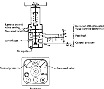
A more simple way of dealing with the same problem is shown in Fig. 2 representing a controller in which all control terms—proportional, integral and derivative—are adjusted in the feedback path and which, moreover, can contain no air flow amplifier, its nozzles having sufficient dimensions for acting directly on the servomotor.
In a way opposite to that of the preceding controller (the three nozzles of which control exhausts of air, the supply of which is constant), this
L _ S _ I
Air supply
Deviation of the measured value from the desired value Feed back
Control pressure
0 §
Measured value,©Q®J
Face view
Fig. 2.—Example of a purely feedback path adjusted pneumatic controller.
controller has both a supply nozzle and an exhaust nozzle between which moves a baffle that gradually covers one of them as it gradually uncovers the other one. In this way, when the measured air pressure Px (fed from a pneumatic transmitter and representing thus the measured and controlled variable) increases versus its desired value (represented either by the adjust- able compression of a spring located in the controller itself or by another air pressure P5 adjusted remotely), this moves upward all the interconnected diaphragms, partly uncovers the lower supply nozzle, partly covers the upper exhaust nozzle and thus increases the control pressure P4. In this example, the controller is direct-acting (i.e. an increase of the measured pressure P1 versus its desired value also increases the control pressure P4) . By simply inverting the connections of the measured pressure P1 and of the desired value pressure P5, this controller becomes reverse-acting (i.e.
ensuring a decrease of control pressure P4 when measured pressure P1 increases versus its desired value).
In the case of a direct-acting controller, an increase of measured pressure Px versus its desired value and, consequently, the increase of control pres- sure P4 is transmitted to the controlled servomotor through an adjustable restriction SM, the position of which governs the speed of response of this servomotor. In fact, the latter is submitted to a pressure Pi lagging behind the control pressure P4 unless the restriction SM is wide open.
Only a part of control pressure P4 acts on the feedback path as a given air flow bleeds to the atmosphere through an adjustable restriction P. In fact, only a pressure P' smaller than the control pressure P4 acts on the
feedback path and the position of the adjustable restriction Ρ serves thus to adjust the desirable proportional band.
Another adjustable restriction D no longer introduces into capacity A the pressure P' (representing the control pressure P4 divided by a coef
ficient depending on the proportional band set by the adjustment of restriction P ) , but another pressure P7 lagging behind P'. In this way, P7 is in some respect the average value of P' instead of being its instantaneous value, which would occur if the adjustable restriction D would be wide open. It is therefore homogeneous to the integral of P' and, therefore, to the integral of control pressure P4 and—as this integral component acts in the feedback path—the adjustable restriction D ensures a derivative control component setting of the overall controller operation.
A last adjustable restriction 7, combined with a fixed booster capacity V, no longer introduces into the capacity I (opposed to capacity A, just as are opposed the two capacities receiving respectively the measured pressure P1 and the desired value pressure P5) the pressure P7, but a pressure P6 lagging behind the latter. This fact and the opposition of capacities A and I mean that their combined action is only momentary and ceases when pres
sures P7 and P6 are balanced, i.e. when pressure P' and, therefore, control pressure P4 are stabilized. Under these conditions, the adjustable restriction I and the fixed booster capacity V create an action homogeneous to the derivative of control pressure P4 and—as this derivative component acts in the feedback path—ensure a method of setting an integral control compo
nent of the overall controller operation.
The lower part of Fig. 2 shows the practical location of the desired value adjustment (by means of a spring) C, of the servomotor speed adjustment SM, of the proportional band adjustment P, of the derivative component adjustment D and of the integral component adjustment I as well as of the pressure gauges indicating the measured and controlled air pressure Px (right-hand gauge) and the control air pressure P4 fed to the servomotor (left-hand gauge).
This figure shows that it is sometimes simpler to adjust the three-term control components entirely in the feedback path of the controller closed loop rather than to adjust them, entirely or partly, in its direct path. It also shows that the use of an air-flow amplifier built into the pneumatic con
troller can be avoided by reducing the number of nozzles used and by giving them fairly sufficient dimensions for acting directly on the controlled servomotor. This, of course, avoids any supplementary time lag and ensures a swifter response of the controller to a given disturbance.
P U R E L Y E L E C T R I C A N D E L E C T R O P N E U M A T I C O R E L E C T R O H Y D R A U L I C C O N T R O L L E R S
W e have outlined, at the beginning of this paper, the interest of measuring the controlled variable electrically. W e have also seen the simplicity and flexibility of pneumatic (or, which would be the same, of hydraulic) opera- tion and, namely, the simplicity with which three-term control components can be adjusted in the feedback path of the controller closed loop. W e can therefore state that the combination of a measurement of the controlled variable performed electrically (and followed or not by any electronic amplification) with a pressure-operated servomotor can ensure a parti- culaily simple and flexible operation of the overall equipment.
This purpose can, of course, be achieved by using an entirely electronic controller measuring the controlled variable electrically, delivering a three- term electric signal (which would contain terms proportional to the devia- tion of the controlled variable from its desired value as well as terms pro- portional to the integral and to the derivative of this deviation) and followed by a merely proportional electropneumatic converter, which would trans- form this three-term electric signal into a proportional air, oil or water pressure with a corresponding pneumatic or hydraulic feedback. This has been already done by several control equipment manufacturers not- withstanding the fact that, although there is no special difficulty in creating purely proportional electric signals, the production of purely electric integral and derivative control components becomes more difficult when more or less long time-constants (i.e. more or less high value adjustable resistances or capacitors or both of them) are required in electric R C circuits.
W e have seen, on the other hand, with what facility an integral and a derivative component can be introduced into the feedback path of a pneumatic (or hydraulic) controller by simply adjusting a restriction coupled with a fixed booster capacity. This is, of course, quite similar to an adjustable resistance and a fixed capacitor in an electric R C circuit with, however, this important practical difference that this does not need high-value resi- stances and capacitors but most simple and sturdy devices, built years before the corresponding electric R C circuits were first used in automatic control and having thus behind them years of experience and of security that no such electric device can yet presently claim.
The use of a pneumatic or hydraulic feedback (comprising in its path the integral and the derivative control component adjustments) in an overall electropneumatic or electrohydraulic controller (the proportional band of which would be adjusted either on the electric or on the pressure side of its direct electropneumatic or electrohydraulic path) would therefore seem most promising from a practical standpoint.
Fig. 3.—Example of a nonlinear electropneumatic controller linearized by feedback:
the general setup.
Moreover, linear control devices, whilst being generally stable, lead with respect to generally less stable relay control devices to the inconvenient of having their speed of action slowed down by their feedback since the very first moment of a disturbance whilst a relay device always operates—
in one direction or in another—at the maximum speed of the available equipment and is therefore not subjected to the same inconvenient. A com- promise between these contradictory conditions seems possible by designing an essentially unstable relay control device stabilized by the presence of a feedback, the latter slowing down and stabilizing the controller action only inside a more or less narrow proportional band domain and letting, on the contrary, this controller operate at its full speed outside of this proportional band domain. Such a compromise should provide the necessary stability of control to a linearized device together with a more energetic response of a basically nonlinear device to large and swift disturbances.
E X A M P L E O F A N O N L I N E A R E L E C T R O P N E U M A T I C C O N T R O L L E R L I N E A R I Z E D B Y F E E D B A C K The electropneumatic controller described in Figs. 3, 4 and 5 uses a pneu- matic feedback path in which are incorporated the integral and derivative control component adjustments as well as an electropneumatic direct
Panel cut-out
Depth = 100
Hand push-button control station
LValve position indicator
Fig. 4.—Example of a nonlinear electropneumatic controller linearized by feedback: the remote control unit.
path in the electric part of which is incorporated the proportional control adjustment. Moreover, this electropneumatic controller uses a simplified nonlinear relay-type action, which is linearized and stabilized by means of a feedback while conserving its peculiar nonlinear features in the event of strong and swift disturbances which would necessitate a particularly ener
getic response of the controller.
The general arrangement of this electropneumatic controller is shown on Fig. 3, the example assumed being that of an automatic control of flow.
The sensing device Ε is, therefore, a differential pressure element measuring the pressure drop across a blend X; the bellows of this differential pressure element actuates the grounded slider of the measuring potentiometer Γ.
Of course, the measured and controlled variable could be anything else than a flow and, in these instances, the potentiometer Y (see alternative 1 at the bottom of the figure) could measure anything else than a differential pressure. This potentiometer Y could also be replaced by a fixed resistance Yx and a mechanically (or thermally) actuated variable resistance Y2 (alter
native 2), or by two variable resistances Y1 and Y2 (alternative 3 which would be that of a control of the proportion of two different flows), or even by a source of variable tension U representing any measured and controlled variable (alternative 4).
.-Balance indicator
\ r Running position—Zero-adjusting position
However, the measuring potentiometer V in alternative 1 is connected in opposition with the manually adjusted desired value potentiometer Η so as to form a measuring bridge fed by a source of tension Uv The slider of this desired value potentiometer Η is connected (in the position 1 of switch N) to the input of amplifier P1 and, from the output of the latter, to the input of a power amplifier P29 both of them being fully transistorized.
The output of power amplifier P2 controls the coils of the double control valve Q either energizing coil <2i and fully opening plug e and the outflow hx of air from space hz to the atmosphere, either energizing coil Q2 and fully opening plug a and the inflow h2 of air from the supply to space A3, either switching off both coils Q1 and Q2 and leaving the pressure in space A3 at its last previously obtained value.
Under these conditions, any deviation of the controlled flow (and, therefore, of the grounded slider of potentiometer Y) from its desired value set by potentiometer Η unbalances this measuring bridge, creates a signal at the slider of potentiometer Η and at the input of amplifier Pl9 energizes one of the coils of the double control valve Q and leads to a pressure change in its space A3. This pressure change indicated by gauge V acts on the servo
motor F with a speed controlled by the adjustable restriction SM in order to restore the controlled variable (flow) to its desired value and thus re
balance the measuring bridge, bring to zero the input signal of amplifier Pl9 desenergize the controlled coil and thus close the previously open plug a or e.
This, entirely relay-type operation is completed by a feedback consisting of a differential pressure element R submitted, on one side of its bellows, to the control pressure in space hz of the double valve Q through an adjust
able restriction D (ensuring integral feedback, i.e. derivative overall control) and, on the other side of this bellows, to the same pressure through an adjustable restriction / associated with a fixed booster capacity Τ (ensuring derivative feedback, i.e. integral overall control), this integral pressure being indicated by gauge W.
This two-term (integral and derivative) pneumatic feedback acts through the differential pressure bellows on the slider of a feedback potentiometer S connected in opposition to a manual zero-adjusting potentiometer having a grounded slider Ox so as to form a feedback bridge fed by a source of tension U2. The slider of the feedback potentiometer S is connected, through a manually adjustable resistance BP (used to adjust the desired proportional band), to the input of amplifier Px.
Under these conditions, any variation of control pressure in space h3 of the double control valve Q applies to the input of amplifier Px—simul
taneously with its direct action on the servomotor F—a three-term feedback signal, adjusted pneumatically by restrictions D and / for derivative and
integral control components and, electrically, by resistance BP for the proportional control component.
These three adjustments as well as the double control valve Q9 the feed
back element R9 pressure gauges V and W and the fixed booster capacity Τ are contained in the electropneumatic controller C. The latter can be located either on the main control panel, together with the remote control unit A and the amplifier unit Β or in the vicinity of the servomotor F. In the first instance, the electropneumatic controller C is remotely connected by means of air piping to the servomotor F with only short electrical con
nections at the panel; in the second instance, this controller C is on the con
trary remotely connected by means of electric wiring to the main control panel with only short air piping to the servomotor. Of course, any inter
mediate solutions are available; all electrical connections are low-voltage D . C , i.e. induction-free.
The remote control unit A contains, besides the already mentioned desired value adjusting potentiometer Η and zero-adjusting potentiometer Ol9 several other elements.
A switch Ν allows either to connect, in normal position 1, the measuring bridge HYto the input of amplifier Px or to switch this bridge off in position 2 in order to adjust the zero of the feedback bridge O^.
A balance indicator J allows a constant checking of the balance of the controller under the opposed actions of the deviation of the controlled variable from its desired value and of the three-term feedback. This balance indicator also serves to check the adjustment of the zero of the feedback bridge, the measuring bridge being switched off.
A position indicator Μ allows constant remote checking of the position of the servomotor F by means of a potentiometer Ζ attached to the latter and fed by a source of stabilized tension C/3. T w o manually adjusted resis
tances mx and m2 allow to adapt the zero and full-scale deviation of the position indicator Μ to the actual stroke of servomotor F.
A switch G allows at any time a change from automatic control (position 1) to manual remote control (position 2). In this last event, coils Qx and Q2 of the double control valve Q are remotely manipulated by push-buttons Κ and L.
The amplifier unit Β located, as the remote control unit A9 on the main control panel, comprises—outside of the already mentioned transistorized amplifier Pl9 transistorized power amplifier P2 and tension sources Ul9 U2 and Uz—the tension source C/4 for operating the double control valve Q1 #
The miniaturized remote control unit A is shown in detail on Fig. 4. Its upper part—with the desired value adjusting potentiometer //—cor
responds to automatic control, whilst its lower part—with push-buttons Κ and L—corresponds to manual remote control.
Fig. 5.—Example of a nonlinear electropneumatic controller linearized by feedback: the electropneumatic controller itself.
In position 2 of switch Ν (the measuring bridge being cut off), the adjust
ment of the zero of the feedback bridge is made in Ol9 checking the balance on indicator /. Upon returning to the normal position 1 of switch N9 the servomotor movements are observed by checking the position indicator M.
The change by means of switch G from automatic control (position 1) to manual remote control (position 2) does not create any shock as the double control valve always remains in its last previously obtained position.
In order to avoid any shock upon returning from manual remote control (after having made some adjustments by means of push-buttons Κ and L) to automatic control, it is simply sufficient to manipulate the desired value adjusting potentiometer Η in order to bring balance indicator / to zero before changing switch G from position 2 to position 1.
Some details of the miniaturized electropneumatic controller C are seen in Fig. 5. This figure shows the locations of servomotor speed adjustment SM9 of proportional band adjustment BP, of integral time adjustment I and of derivative time adjustment D9 as well as of the integral air pressure gauge W. A l l these elements—apart of the control air pressure gauge V located on the outer side of this controller—are fixed on a tray, easily sliding for necessary adjustments out of a housing in which this tray can be locked in order to prevent unauthorized persons from handling these control adjustments.
9 - 60143045 I db Μ
S U M M A R Y
The author mentions two different methods of achieving a three-term (proportional, integral and derivative) control in modern pneumatic con- trollers provided with pneumatic transmitters, the latter converting varia- tions of the measured and controlled variable—whatever its physical nature may be—into strictly proportional variations of an air pressure fed to the input of the controller.
The first, and more conventional, of these methods consists in operating on the air pressure supplied by the transmitter, i.e. in fact on the measured and controlled variable itself and in adjusting the proportional, integral and derivative control terms in the direct path of the controller closed loop leading from its input to its output.
The second, less usual, method consists in operating in the feedback path of the controller closed loop, leading from its output to its input and in using a feedback having a transfer function approximately inverse of the desired overall controller transfer function. In this way, an overall integral action can be approximately achieved by using a derivative feedback and inversely, an overall derivative action can be approximately achieved by using an integral feedback.
One example is given of a combined direct path-feedback path adjusted pneumatic controller in which the derivative and proportional control terms are adjusted in the direct path and the integral control term is adjusted in the feedback path. This controller is provided with several relatively small-diameter nozzles followed by an amplification of the control medium flow.
Another example shows a purely feedback path adjusted pneumatic controller in which all of the three control terms are adjusted in the feed- back path. This more simple controller uses a single large-diameter nozzle which cannot be followed by any control medium flow amplification, so as to avoid any supplementary time lag and to ensure a swifter response of the controller.
It is recognized that the combination of a measurement performed electrically with a pressure-operated servomotor ensures particularly flexible operation.
This type of control can, of course, be achieved by a purely electric three- term P I D controller followed by a conversion of the resulting electric signal into a strictly proportional final pressure signal. There is no special diffi- culty in creating electric signals proportional to the deviation of the con- trolled variable from its desired value, but electric integral and derivative signals become more difficult to create when more or less long time-con-
stants are involved. On the contrary, pressure integral and derivative signals are most easy to create even with very long time constants.
Finally a nonlinear relay-type electropneumatic controller is presented, linearized by feedback so as to combine the necessary stability of control with a more energetic response of a basically nonlinear device to strong and swift disturbances. This controller uses a pressure-electric feedback with adjustment of the integral and derivative control terms on the pressure side and of the proportional term on the electric side, all these three terms being adjusted in the feedback path.