Analysis of Conveyor Belt Impact Resistance Data Using a Software Application
Anna Grinčová
1, Miriam Andrejiová
2, Daniela Marasová
31Faculty of Electrical Engineering and Informatics, Technical University of Kosice, Letna 9, 042 00 Kosice, Slovak Republic
2Faculty of Mechanical Engineering, Technical University of Kosice, Letna 9, 042 00 Kosice, Slovak Republic
3Faculty of Mining, Ecology, Process Control and Geotechnology, Technical University of Kosice, Park Komenskeho 14, 042 00 Kosice, Slovak Republic anna.grincova@tuke.sk, miriam.andrejiova@tuke.sk, daniela.marasova@tuke.sk
Abstract: Transportation is an important logistics activity within production systems, affecting continuity of the production process. High-capacity, cost-efficient, and energetically undemanding, continuous transportation systems include the conveyor belt system. A crucial and the most sensitive component thereof is a conveyor belt which is exposed, within the production processes, to the impacts that give rise to the damage and degradation process. Therefore, the issues related to increasing the service life and the operational reliability of conveyor belts are highly topical. The aim of the article is to discuss the issues regarding the measurement analysis within the testing of conveyor belts in terms of software optimization. The role of the created AnCoBE (Analysis of Conveyor Belt) software application is to apply selected mathematical and statistical methods and Java technology in order to support processing and evaluation of data obtained by experimental research of evaluation of utility properties of conveyor belts in terms of their dynamic stress. The experimental tests herein were focused on the determination of conveyor belt impact resistance and the description of damage caused to conveyor belts by the related stresses.
Keywords: conveyor belts; regression model; software application
1 Introduction
The belt conveyor systems are used in a broad extent for the transportation of various types of materials and are exposed to various surrounding conditions, weather, and environmental impacts. According to Kulinovski [1], for belt conveyors, the transport task can be defined as a process the purpose of which is
to transport the set quantity of handled material within a defined period of time between the set loading and offloading locations.
In terms of belt conveyor operation, the most important structural component the conveyor belt. According to Zur [2], the belt conveyor is a limited-range, continuously moving transport facility that carries material on the belt surface, between two belts or inside a belt. According to Boroska [3], the conveyor belt transfers the resistances formed during the belt movement and serves for the transportation of materials, loads, or persons. Practical experience indicates that the most critical point is the place where the material is loaded onto the conveyor, the so-called chute. At the chutes, point impact loads are formed, being one of the main reasons for conveyor belt damage. If the impact energy is higher than the ability of the supports and the conveyor belt to absorb this energy, then conveyor belt damage occurs, especially at its upper cover layer, in form of transversal and longitudinal scratches, disruptions, and punctures, which can even cause damage to a conveyor belt carcass.
The conveyor belts impact resistance is classified as the ability of a conveyor belt to absorb the impact energy of the material’s fall onto the belt, i.e. absorb the impact energy by the deformation work of the conveyor belt without damaging the belt.
In the theoretical part herein, the Authors focused their efforts on the creation of mathematical models, with an aim to accurately describe conveyor belt properties.
The mathematical apparatus for the determination of reliability and optimal service life of the conveyor belts, while applying the renewal theory, was described in papers [4, 5]. The issues regarding conveyor belt damage were also discussed in papers [6, 7, 8, 9]. Models related to punctures of rubber-fabric and steel-cord conveyor belts were also discussed in papers [10, 11, 12].
The aim of this article is to provide the information on the solution of the problem regarding the analysis of measurements in the testing of conveyor belts during the impact tests, with regard to software optimization. At present, there is a simple tool for the measurement analysis; however, this tool was designed with regard to the measurements obtained from the device which is not currently used for the measurement recording. The aim of the research was to design a more complex tool for a deeper analysis of the problem with regard to new data provided by a new measuring device. The developed software application contains the tools for the analysis of the data measured, using the PP065 electronic device, for the manipulation therein, representation of relationships and the creation of regression models.
2 Material and Methods
2.1 Experiment and Data Acquisition Description
The testing equipment (Fig. 1) located at the Institute of Logistics of the Technical University in Košice is used for the impact testing of the conveyor belts. The purpose of the conveyor belt testing is to determine their impact resistance. The testing equipment contains a hydraulic system for belt specimen clamping, another hydraulic system for stretching a specimen during the test, and a laser detector recording the real-time height of the drop hammer. The structure of the testing equipment is based on the current requirements resulting from the conducted research as well as on the requirements of the conveyor belt manufacturer in Slovakia.
Figure 1 Testing equipment
During the test, the specimen of a selected conveyor belt is fixed in hydraulic clamps and is stretched using the force equal to 1/10 of the belt strength specified by the manufacturer. Subsequently, a drop hammer of a selected weight and shape is dropped onto it in a free fall. The drop hammer weight may range between 50 kg and 110 kg. In the testing, two types of end-pieces are typically used: pyramid- shaped and sphere-shaped (Fig. 2). The type of the used drop hammer end-piece characterizes the type of the transported falling material, in particular, a pyramid represents the impact of sharp-edge material and a sphere simulates the impact of non-compact, crumbling material. The drop hammer may be dropped onto the
conveyor belt from the maximum height of 2.6 m. The various belt types are used in the testing: rubber-fabric or steel-cord conveyor belts. During the testing, real- time height of the drop hammer, real-time impact and stretching forces of the conveyor belt are recorded [2].
Figure 2 Types of impact end-pieces
The test evaluation, in case of identification of the wear caused by the puncture, consists of the visual inspection of a conveyor belt and the identification of particular values of input parameters (weight, height) at which the conveyor belt damage occurred. Examples of the damage of the conveyor belt specimens are in Fig. 3.
a) b) c)
d) e) f)
Figure 3
Examples of the damaged conveyor belt specimens
Figure 3a) shows the specimen without any visible signs of damage. The upper cover layer was undamaged, without any cracks caused by the falling material.
Similarly, the lower cover layer did not carry any damage signs either. At the same time, no anomalies were observed in a tested specimen. The damage was manifested in the specimens (3b, 3c) by cracks or puncture at the site of simulated
material’s impact. The conveyor belt fabric carcass was not visible through the crack and no torn fibers were present. Complete damage occurred in specimens 3d and 3e, where the fibers from the fabric carcass of the specimen were clearly visible; they protruded to the surface through the perforation in the cover layers.
The most severe degree of damage – puncture (specimen 3f), is characteristic with the perforation interconnecting the lower and the upper cover layers. In the formed crack, torn carcass fibers may be observed; they may protrude to the surface. The upper and the lower cover layers are visibly damaged. Locally, parts of the upper cover layer may also be torn.
2.2 Regression Analysis
Many scientific and engineering problems include the examination of relationships between two or more variables. Regression analysis is a tool appropriate for solving these types of problems. The main objective of multiple linear regression is to search the linear relationships between a dependent variable and several independent variables and thus enable concurrent examination of the effects of several variables. The relationship between the explained (dependent) variable y and explanatory variables xj, (j1,2,,k) may be expressed by the following general linear regression in Eq. 1:
x x x x x kxk
y 0 1 1 2 2 3 3 4 4 5 5 , (1)
where 0 is referred to as the intercept and coefficients j for j1,2,,k are referred to as the regression model parameters and is a random error of the regression model. In a standard case we assume that a random error has normal division with the mean value of 0 and the constant variance. A matrix notation of the linear regression model is shown in Eq. 2:
X
y , (2)
where y is the n-element column vector of the measured values of the explained variable, X is the matrix of the n
k1
type of the measured values of the explanatory variables xk, is the
k1
-element column vector of unknown model parameters, and is the n-element vector of random errors which represent the random component of the regression model.To estimate the regression model parameters, we will use the method of least squares. To verify the statistical significance of the model, we will use the F-test of the statistical significance of the model. Statistical significance of the individual regression model parameters will be verified using the test of statistical significance of a regression parameter. Evaluation of the strength of the determined relationship between quantitative variables is carried out using the correlation analysis.
2.3 Applied Technologies
The problem in question was solved used using the Java language together with AWT and Swing technologies provided by this platform and the JMathPlot, Apache POI, Apache Commons Math libraries. The main advantage of the Java programming language is the independence of the platform. Java is currently, one of the most important and most frequently used programming languages [13] in the world. It is derived from C++, which is a direct descendant of C. Plenty of Java characteristics are derived particularly from these two languages.
3 Software Application
3.1 Hardware Requirements and Program Functions
The program serves for the analysis and subsequent work with measurements. The measured values are recorded using the PP065 electronic device (Fig. 4) which facilitates the control of the testing equipment and the recording of the measurement results.
Figure 4 PP065 electronic device
Recommended configuration for launching the program: Pentium class processor (500 MHz and more), 128 MB of RAM main memory and 10 MB of disc space.
This recommended configuration only provides for launching the program; the main memory capacity depends on how many measurements we want to work with at the same time. Complete measurement, collection and evaluation of data are carried out as shown in Figure 5.
Recording of the measured values is carried out using the USB interface. The measured values are saved in form of text files. Data obtained from them are further processed using the created application. On the basis of these data, the software creates the mathematical models and verifies their statistical significance and makes graphical comparisons of the measured and the modeled data.
Figure 5
Collection and evaluation of data
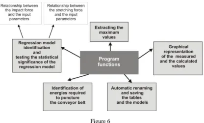
Individual items of the saved file represent: time in milliseconds, height in millimeters, stretching force in kilonewtons, and impact force in kilonewtons. One text file contains 10,000 lines. Basic program functions are listed in Figure 6.
Figure 6 Program functions
The graphical user interface (GUI) in the entire program is created using the Swing library. The main program structure consists of the main menu, information panel, and the main panel. The information panel displays short messages on the program status and error messages. Error messages which require closer user attention are presented in a pop-up window.
The main panel also serves as the storage for program panels. This principle facilitates persistence of the main menu and the information panel when switching between the program functions. All program tools are thus independent panels that are inserted in the main program panel, as required. The program inputs are thus the measurements obtained from the PP065 electronic device in form of text files.
These are subsequently analyzed using the amplitude searching algorithm. All the data, the measured and the analyzed, are saved in the memory, until the program is terminated or until other measurements are loaded.
3.2 Analysis of Input Files
As the drop hammer falls down onto the belt, the sensor records, using a laser, its real-time height; other sensors record the impact and stretching forces. For the illustration purposes, we will present the analysis and evaluation of the data obtained when testing the impact resistance of rubber-fabric conveyor belts.
Figure 7
Graphical representation of impact force (blue) and height curve (red)
The plot in Figure 7 shows the development of the impact force and the height of the drop hammer in time for measurements on the textile-rubber conveyor belt with a 50 kg drop hammer dropped from the height of 0.4 meters. As shown in [12], there is a relationship between the impact force and the stretching force;
therefore, to solve the problem of analysis of files, it is sufficient to focus only on one of the two forces.
The plot in Figure 8 shows the curve taken from the previous plot with added points designated with Arabic numerals. This plot represents one, particularly the first amplitude of this file:
• Point 0 coordinates represent the time and height from which the drop hammer started to fall
• Point 1 coordinates represent the time and height when the drop hammer fell down onto the belt
• Point 2 coordinates represent the time and height where the drop hammer was burrowed the deepest into the belt
• Point 3 coordinates represent the time and height when the drop hammer bounced off the belt
• Point 4 coordinates represent the time and height where the drop hammer bounced and from where it started to fall onto the belt again
Figure 8
Graphical representation of the curve of one amplitude
The amplitude is thus the interval since the drop hammer started to fall from certain maximum height fell onto the belt and then bounced off to the following maximum height. Each file contains several such amplitudes; accurate determination thereof requires creation of the algorithm, i.e. the procedure how to identify these amplitudes correctly. Firstly, we will specify the data required for the correct identification of amplitudes. An important fact is that the measurement always begins with the drop hammer’s fall; it means that at time 0 the first amplitude has the maximum height, i.e. the height from which the drop hammer is dropped.
Data required for amplitude identification:
The maximum force and the time of maximum force
The minimum height and the time of minimum height
The maximum height prior to the impact and the time of maximum height prior to the impact
The maximum height after the bounce and the time of maximum height after the bounce
The drop height of the drop hammer and the time of impacting the belt
The bounce height of the drop hammer and the time of the drop hammer’s bounce of the belt
The measurement lasts 10 seconds and data are recorded every millisecond, it means that we have 10,000 data on the drop hammer height, the impact and the stretching forces. It is important that the number of records is final. Another important factor is that when the drop hammer falls down from the height x, after
the bounce the height can no longer achieve this value; this fact has the same effect in both measured forces. It means that every maximum value of the force and the height of the amplitude must be higher that the appertaining maximum value of the following amplitude. This also applies for the minimum height, i.e.
how deeply the hammer penetrates the belt, except in the case of belt puncture. It is also necessary to note that if the height is 0, it means that the drop hammer is on the belt’s level. Using these facts, the algorithm was created for searching amplitudes in each measured file. With the use of the found amplitudes, required plots and models will be created in the following step.
With the algorithm that searches all amplitudes we have to bear in mind that small inaccuracies occur at the measurements (e.g., at vibration, etc.) which result in the recorded amplitude. Therefore, not all the found amplitudes may be considered as valid. These invalid amplitudes are always located behind the valid amplitudes, unless certain invalid amplitude exceeds the values of normal amplitude.
3.3 Program Settings
Program settings are used to set certain behavior rules for the program which are saved in the disc. These settings include an option to set
The force (impact or stretching) we primarily want to work with in the program
The algorithm to be used in the model creation
Whether the program is to search all amplitudes or only the first ones,
The data elimination prior to the analysis (elimination of invalid amplitudes)
The renaming certain variables that will be used for the creation of plots and tables
Standard settings are listed in Table 1. (All variables relate to the current amplitude.)
In the Force item we will select the force we want to work with. The program works with the selected force in cases when the force selection option is not enabled: Stretch (stretching force), Impact (impact force). In the Algorithm item we will select the algorithm for analyzing the input files: Only first amplitudes (the algorithm will select only the first amplitudes from each file), All amplitudes (the algorithm will select all amplitudes).
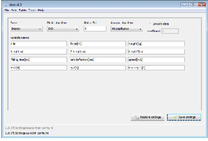
Figure 9 Settings panel
Table 1 Standard settings
Name Explanation Name Explanation
File File name falling time[ms] Time of the drop hammer’s fall onto the belt
force[kN] Selected stretching force belt
deflection[mm]
The depth into which the
drop hammer was
burrowed
weight[kg] Drop hammer weight speed[m/s] Speed of the drop hammer’s impact on the belt
height[m] Drop height Ep1[N] Potential energy in the drop height
2.
height[m]
Bounce height Ep2[N] Potential energy in the bounce height
height T[m]
Theoretical height obtained from the file name
Ep2 - Ep1 [N] Difference between potential energies
In the Model algorithm item we will select the algorithm for solving the Ax = b problem in the model calculation using the method of least squares. In the Alpha item we will set the level of significance for the determination of significance of regression parameters. When we put a cross next to Smooth data, the coefficient value will be used and the input data will be eliminated prior to the analysis using the moving average method. The Restore settings button changes all setting to default values.
The Save settings button will save the made changes; without saving the changes, all changes will be lost. The changes are also saved in the config.ini file, so they will not be lost after the program is restarted. In the Variable names it is possible to set the name under which individual amplitude values will be displayed, for example when saving the model in the .xls format, creating the table using the Edit data, etc.
3.4 Program Tools
All the data, the measured and the analyzed, are stored in the memory until the program is terminated or until other measurements are made. They are stored in the structure accessed using the created interface. In addition to the data necessary for the identification of amplitude, also the data on belt name, drop hammer weight, assumed height from which the drop hammer was dropped, and data on energies are obtained and kept; these data are listed in the Analysis of Energies section. The program tools are accessible from the main menu and some of them from the Loaded files menu.
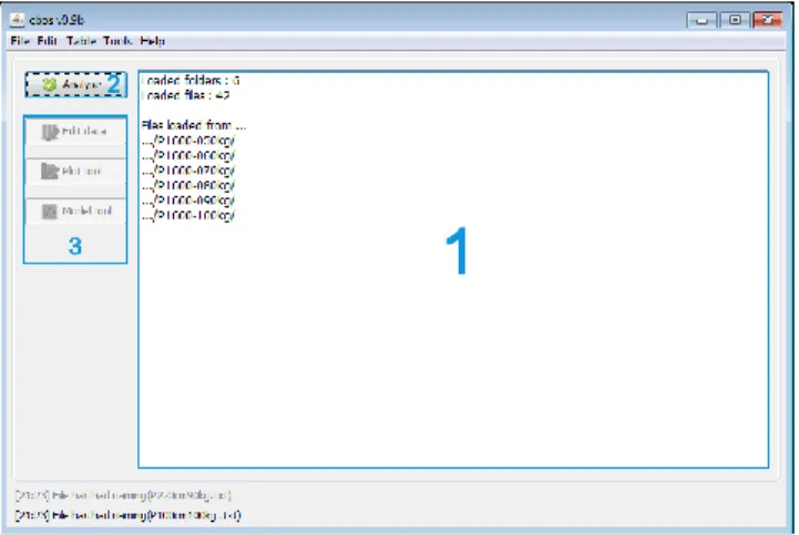
Figure 10 Loaded measurements
3.4.1 Loading of Measurements
The measurements may be loaded in any of the program statuses (except the error status) from the main menu via File > Open Files. It is possible to select only the folders, while their name must consist of the chain *NNNkg, where * is an arbitrary chain and NNN is the weight of the used drop hammer in kilograms in measurements contained in this folder. The folders contain .txt files with measurements which should have the *NNNcm.txt format, where * is an arbitrary chain and NNN is the height in centimeters from which the drop hammer was
dropped at such measurement. Unless the files end with NNNcm.txt, it will not be possible to work with the assumed height; this, however, currently does not represent any limitation, as we can identify the height from the file. The program only works with the theoretical height, if the user wants to sort out the measurements into categories by the height from which the drop hammer began to fall onto the belt.
After the measurements are loaded, the program automatically switches to Loaded files panel (Fig. 10) which contains, inter alia, the Analyze button (2) used to launch the analysis of files. The information on the analysis of loaded files and the results are displayed in the text section (1). Fast access to the program tools is possible by using the 3 button.
3.4.2 File Preparation
A tool (Fig. 11) is created to provide assistance with renaming the files.
Figure 11 File renaming tool
The main table (1) shows the original and new names of files. Button (2) is used to load the recorded files. In section (3) we will select the prefix of renamed files (NNNcm), in (4) we will set the height at which the measurement began for the first file (in cm), in (5) we will select the value in which the height in cm should be increased in each following file. Button (6) is used to rename the files according to the set parameters and button (7) is used to save the required changes.
3.4.3 Data Editing
To edit the analyzed data, the tool (Fig. 12) was created; it facilitates displaying these data in form of tables. The tool enables viewing the data after individual measurements, whereas the data may be displayed either as the data on all amplitudes of this measurement or by individual amplitudes. The data may also be modified or all amplitudes may be deleted. It is also possible to display the plot (Fig. 12) which shows the points identified by the algorithm for searching the amplitudes. These points are identical to points in the plot in Fig. 8 and their meaning is explained in the Analysis of Input Files section.
Figure 12
Graphical representation of height curve
Data editing serves for the adjustment of already analyzed measurements; to access the panel, we will enter the route Edit > Edit data, or Edit data from the Loaded files panel. Individual functions of this panel are explained in Figure 13.
When the table (1) is selected, we can choose Amplitudes (the table will display the data from all files for the amplitude selected in 2) or Files (displayed data on all amplitudes for the file selected in 2). For the output table we can select various parameters (4, height, weight, impact force, speed...) and the selected parameters will be displayed in the window (5). Parameter addition or removal is carried out using buttons (6). Using the Plot file function (7), we can draw the plot of the file showing the height in time and the data on where the algorithm has found the amplitude. The Delete amplitude functions enables deletion of the selected amplitude. The resulting table will be displayed in the window (3).
Figure 13 Data editing tool
3.4.4 Data Depiction
A tool for plot creation enables creating 2D and 3D plots from the measured and analyzed data. Depicted data may be displayed as a point chart, line chart, or a combination of both. The tool allows sufficient freedom when combining the depicted data. The data may also be automatically differentiated according to the selected parameters (e.g., by weight or height).
Data depiction is carried out using the Plot tool panel; to access the panel, we choose Tools > Plottool, or Plot tool from the Loaded files panel. Individual functions of this panel are explained in Figure 14.
Figure14 Tool for plot creation
The Data function enables selection of data (1), selection of the file (3) and the amplitude (2, Impact order) for which we want to depict the data. When selecting the data to be used for a plot creation, we may choose the Measured Data (original data) or the Calculated data (analyzed data). Coordinate system selection is enabled by the Axis function (5). An option to sort the data by weight or height, or not to sort them (only for the analyzed data), is enabled by the District by function (6). When drawing the plot, it is possible to choose a plot type (7, Plot type): point, line, combined (point and line charts will be drawn at the same time using the same color. Buttons (8) serve for depicting or adding the data in the plot (Add plot). The plot as such is displayed in the window (4).
Zoom mode works exactly as a zoom tool, so if we want to adjust plot borders, they must be set in plot settings where it is also possible to rename the axes and adjust the range. The plot may be saved in the .png format. In table with the depicted data, it is possible to change color of individual plots, but not to change the data.
3.4.5 Model Creation
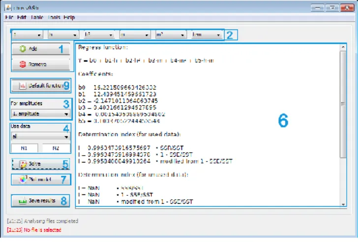
The regression models are created using the tool (Fig. 15) enabling the real-time calculation of various models according to the set parameters. The inputs for the creation of a regression model are regression parameters and the data from which the model will be calculated. The resulting data on the created model includes regression coefficients, determination of appropriateness of individual coefficients and a determination index. The model is evaluated by applying the method of least squares.
The Model tool panel serves for the creation of regression models from the analyzed measurements; to access the panel, we choose Tools > Model tool, or Model tool from the Loaded files panel. Individual functions of this panel are explained in Figure 15.
The Add/Remove function (1) serves for adding/removing a regression parameter from the regression function. Each parameter may be determined using the drop- down menu (2). The For amplitudes function (3) enables selection of the amplitude for which we want to create the model. Selection of the data we want to use for the model calculation is carried out using the Use data function (4). Model solving is enabled by the Solve function (5), whereas the model results are displayed in a separate window (6).
The Plot model function (7) enables model depiction. The resulting model may be saved using the Save results function (8) in the .xls format. This function enables saving also the depicted model plot.
Figure 15 Model tool
3.4.6 Analysis of Energies
The software application also enables the analysis of energies. The real-time records for the drop hammer height may be used to identify the energy that the belt is able to absorb, just before the damage occurs on the basis of potential energies before and after the drop hammer bounce off the belt. Therefore, it is possible to make appropriate adjustments of input parameters to avoid the belt damage by puncture.
Conclusion
The electronics used in experimental measurements, aimed at evaluation and assessment of utility properties of conveyor belts, in terms of their dynamic stress, have until recently, facilitated only recording of measured values. Complicated and often time consuming initial processing and evaluation of the measured data is replaced with the AnCoBe software application described herein. This software application is particularly specialized for the solution of conveyor belt impact resistance in dynamic stress. Installation of this application does not require any special hardware or software. Similarly, work with the application does not require any special computer skills or elaborate training. The AnCoBe application includes a user guide, even though this software application control is intuitive.
The application is freely distributable, including all sources and documentation, enabling the potential development and update by users as an open source method.
Acknowledgements
This article is the result of the Project implementation: University Science Park TECHNICOM for Innovation Applications Supported by Knowledge Technology.
ITMS: 26220220182, supported by the Research & Development Operational Program funded by the ERDF and project KEGA 072TUKE-4/2014.
References
[1]
P. Kulinowski: Simulation Studies as the Part of an Integrated Design Process Dealing with Belt Conveyor Operation, Maintenance and Reliability. Vol. 15, 2013, pp. 83-88[2]
T. Żur: Belt Conveyors in Mining. Poland: Śląsk Publishers, Katowice 1979[3]
J. Boroska, Daniela Marasova: Nowe kierunki i doswiadczenia w zakresie budowy i eksploatacji tasm transporterowych i urzadzen z nimi wspólpracujacych, Gliwice: Politechnika Slaska, 1995, pp. 55-66[4]
A. Pavliskova: Reliability and Continuous Regeneration Model, Acta Montanistica Slovaca. Vol. 11 (2) 2006, pp. 119-121[5]
A. Pavliskova: Deterministic Strategies and Life-Time, Acta Montanistica Slovaca. Vol. 12 (3) 2007, pp. 265-269[6]
U. Bugarić et al.: Reliability of Rubber Conveyor Belts as a Part of the Overburden Removal System - Case Study: Tamnava-East Field Open Caste Mine, Tehnički vjesnik. Vol. 21 (5) 2014, pp. 925-932[7]
U. Bugarić et al.: Lost Production Costs of the Overburden Excavation System Caused by Rubber Belt Failure, Eksploatacja i Niezawodnosc .Vol.14 (4) 2012, pp. 333-341