P R O C E S S C O N T R O L A P P L I C A T I O N S
B E N G T J I E W E R T Z
Saab Aircraft Company, Linkoping, Sweden
The computer has been developed with the aim of controlling and regulating complicated real-time processes or physical systems where a high sampling rate is needed. It is designed with emphasis on high computation speed both with regard to internal operations and input-output signal transfer.
The computer is a general purpose digital computer, completely transistorized.
For communication with the process to be controlled, the computer is equipped with a flexible number of input and output channels. The com- puter is designed to convert different types of input signals, analog voltages, binary pulses, etc., to suitable form before computation. Also the computed output signals are converted to fit the physical system to be controlled. For the processing of large volumes of data and program systems the computer can be equipped with a magnetic tape system, e.g. the Saab Saraband.
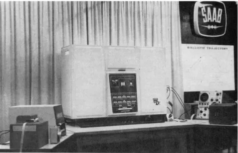
The prototype computer with tape reader, decimal readout panel and tape punch is seen in Fig. 1. A summary of the specifications of the com- puter is given in Table 1.
L O G I C A L D E S I G N
The machine works on binary numbers in parallel operations and with one- address instruction. The word length is 20 bits, including the sign digit.
The machine has been designed with two separate memories, one for instructions ( I M ) and the other for data ( D M ) according to the block diagram of Fig. 2. The operation part of an instruction word which is read out from the instruction memory is fed to the control unit ( C U ) . Micro- program pulses from this unit control the internal operation of the different units of the machine. The address part of the instruction word is used in the data memory where it selects the data to be operated on. Data from the D M or from an input channel of the input-output unit ( I O U ) are trans- ferred to the arithmetic unit ( A U ) . After arithmetic operation, data are returned to the D M for intermediate storage or fed to one of the output channels.
When an operation is to be executed by the computer, the sequence of microoperations begins with the transfer of the operation part of the in-
Fig. 1.—Central computer SAAB D2 with tape reader, decimal readout panel and tape punch.
struction word to the operation register of the control unit. A t the same time the address part is transferred to the address register of the data memory and the address of the next instruction word is set by adding + 1 to the address register of the instruction memory. After these transfer operations, the memory timing cycle is started. During this, both memories are running in parallel. The instruction memory gives the next instruction and the data memory the data for the actual operation. After the read phase of the memory cycle, the data are transferred to the arithmetic unit where the ope- ration is carried out.
When an instruction is modified, the new address part of an instruction word is read out of an index register cell of D M and transferred from the data memory register to the instruction memory register, cf. Fig. 2. In transfer operations, the address part from the instruction memory register is fed to the address register of I M . The operation "store instruction address" is accomplished by a transfer from the address register of I M to the data memory register.
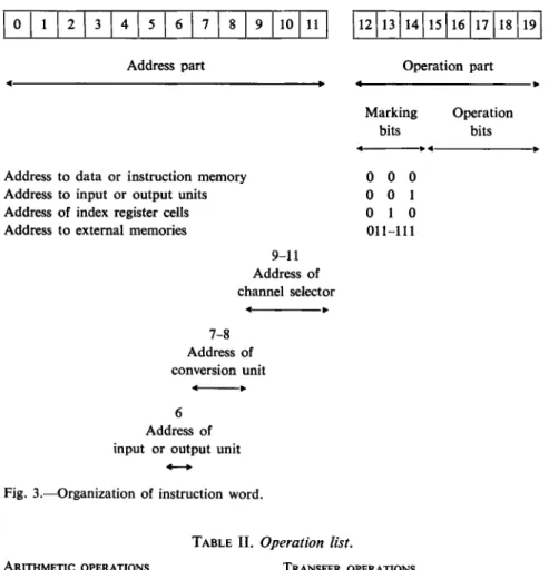
The organization of the instruction word is seen in Fig. 3. The three marking bits of the operation part specify if the address part refers to (/) data or instruction memory; (2) input or output units; (3) index register cells; and (4-8) extra memory units of 4096 words.
A l l cells of the data memory can be used as index register cells to modify instructions. A n input or output channel is addressed by the address part
T A B L E I . Specification summary.
L O G I C A L DESIGN Parallel binary machine Word length 20 bits One-address instructions Fixed binary point operation Program selection according to priority graded signals
I N P U T - O U T P U T SYSTEM
N o . of input channels 32, 64, 128, . . No. of output channels 32, 64, 1 2 8 , . . Converters for analog signals,
error 0.1 %
Converters for binary pulses in serial, parallel, and sedecimal form Provision for paper tape reader,
punch, and electric typewriter Provision for magnetic tape system
SPEED OF OPERATION
Clock frequency 2.5 Mc/s Add, subtract, write 7 μβ Multiplication 23 μβ
Division 29 μβ
Input analog conversion 40 μ8 Output analog conversion 5 μ&
MEMORY U N I T S
Data memory max 2048 words Instruction memory max 4096 words External ferrite core memory
max 5 χ 4096 words Magnetic tape memorya
INSTALLATION DATA OF CENTRAL COMPUTER Size 130 x 1 0 0 x 5 0 cm Weight 200 kg
Power requirement 220V ± 1 0 % , 50 cps Power consumption 300 W
a For example, two Saraband systems of max 16 recorders, each of 106 words.
of the instruction word according to Fig. 3. A l l input and output channels are thus regarded as equivalent to a data memory cell.
The computer has a manually set or externally operated program inter
rupting feature for the selection of a number of different computing se
quences. Such an interrupt signal can also be used to read data from an input channel to the computer. When an input signal arrives, the computer stops
INPUT-OUTPUT UNIT, IQU
C H A N N E L S E L E C T O R S C H A N N E L S E L E C T O R S
O U T P U T C O N V E R S I O N ;
I N P U T . ICON V E R S I O N ' ι
D A T A M E M O R Y R E G I S T E R
IOU I N - O U T P U T . D E C O D E R ANDl S U B C O N T R O L
D E C O D E R A D D R E S S R E G I S T E R
INSTRUCTION MEMORY, IM I N S T R U C T I O N £
M E M O R Y R E G I S T E R
I E
I N S T R U C T I O N M E M O R Y
M I C R O - O R D E R P U L S E S T O A L L UNITS
ARITHMETIC UNIT.AU
A R I T H M E T I C O P E R A -
A C C U M U L A T O R R E G I S T E R
CONTROL UNIT, CU
O P E R A T I O N A L U N I T
Fig. 2.—Block diagram of process control computer SAAB D 2 .
0 1 2 3 4 5 6 7 8 9 10 11 12 13 14 15 16 17 18 19
Address part Operation part
Address to data or instruction memory Address to input or output units Address of index register cells Address to external memories
9 - 1 1 Address of channel selector
7 - 8 Address of conversion unit
Address of input or output unit
Marking bits
Operation bits
0 0 0 0 0 1 0 1 0 0 1 1 - 1 1 1
Fig. 3.—Organization of instruction word.
ARITHMETIC OPERATIONS Add to A R
Subtract from AR Add absolute value to A R Subtract absolute value from A R Multiply
Divide Store
Store and clear A R
Add to A R and store, clear A R Clear A R add to A R
Store M R Shift left Shift right
Zero to sign position
T A B L E I I . Operation list.
TRANSFER OPERATIONS Read to instruction memory Unconditional transfer control Transfer if content in D M R negative Transfer if content in A R positive Transfer on overflow
SPECIAL OPERATIONS Counting
Store instruction address Memory shift
Abbreviations: AR, data memory register.
AUTOMATICALLY PERFORMED OPERATIONS Transfer according to program selector Modification according to index register Read from magnetic tape
Store on magnetic tape
accumulator register; MR, multiplication register; and D M R ,
the main operation program and jumps to a special sequence which takes care of the new data. The sequence can be short, e.g. consisting of multi
plication with a scale factor and storage of the scaled data in a special cell.
After this, the computer continues in the main program. Often, several input signals are characterized by being available for only a short time. The interrupt signals are for that reason graded according to priority.
The computer uses rather few instructions, the operation list of Table 2 shows a total of 22 basic operations. Beside these basic operations, which are used by the programmer, Table 2 also shows some special built-in operations performed automatically by the computer.
M E M O R Y U N I T S
The use of separate memories for data and instructions has several advan
tages. One is that the time for short operations, addition, subtraction, etc., is one-half compared with a machine with only one memory. There is also less danger that the stored operation program can be destroyed accidentally.
The memories are built with ferrite cores and have a cycle time of 5.6 //s.
They are of the coincident current type and use 50 mil cores of material S4.
The driving and selecting circuits are designed without current transformers.
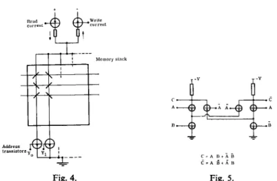
This makes it possible to keep small drive current tolerances that give a reliable operation over a large temperature range. From a central drive current generator read and write currents are fed through the cores according to Fig. 4. The address selection is made by an address transistor. This is of a complementary type that can be passed both by the read and the write currents.
The ferrite core memories within the computer cabinet have a maximum capacity of 2048 words for data and 4096 for instructions. With the use of the marking positions of the instruction word it is, however, possible to extend this memory capacity to 5 χ 4096 words. The memory capacity can also be increased by addition of magnetic tape units, e.g. of the type Saab Saraband. This unit has facilities for separate search of a block. The tape memory is regarded as an input unit and the search of a block starts when this is addressed as an input channel. When the search is completed, word by word is read in to the computer automatically by a high priority graded program interrupting transfer. It is not necessary, then, to use buffer memories.
A R I T H M E T I C U N I T
The arithmetic unit has 20 bits including the sign digit. Negative numbers are represented as the complement of two and the machine uses fixed binary point arithmetics. The arithmetic unit is not designed with floating point
Fig. 4. Fig. 5.
Fig. 4.—Memory driving and selection circuits, identical for row and column selection.
Fig. 5.—Basic circuit of arithmetic unit with logical expressions.
number system or operation with double word length as these operations can be easily programmed without too great loss of speed.
The addition part of the arithmetic unit is of the ripple-through type. It consists of four identical circuits of the type shown in Fig. 5. Except the input addend and augend signals, the function of the adder depends upon the control signals. These are derived from a separate subcontrol unit that controls the arithmetic operation to be done. The use of circuits with com- plementary symmetric logic makes the adder system fast and reliable. A n addition time, except administration, is equal to the time the carry needs to ripple through the 20 binary positions and is equal to 0.8 //s.
C O N T R O L U N I T
Each order is built up by a sequence of microoperations or pulses of diffe- rent length and at different times, which are fed to all units of the machine.
The microoperations are generated by a sequence of microorders of given duration on a number of channels. The sequence of microorders, which is typical for a special operation, is selected in special units, one for each operation. These are called microorder generators in the block diagram of Fig. 2. They are arranged as crossboards and are thus flexible so that an operation can be easily changed. The computer can make use of a maximum of 32 operations. The transition from a microorder to a microoperation is carried out in the operational unit, cf. Fig. 2.
In addition to the central control unit there are a number of subcontrol units in the machine. For example, there is one for the arithmetic unit, one
for the memories, and one for the input-output unit. These subcontrols take over some of the control functions from the central unit during ope- ration.
I N P U T - O U T P U T U N I T
The input-output unit is designed as an integral part of the machine and comprises circuits, which matches peripheral equipments with the com- puter. Signals from different types of data transducers can thus be accepted by the computor. Input signals are analog voltages, binary pulses in serial, parallel, sedecimal form, etc. There are a number of input conversion units, each designed to convert a signal of special characters. The conversion units are fitted with a number of separate input channels. Analog signals are converted by means of an analog-digital converter. The output system contains, similarly, output conversion units with channel selectors. Output signals are D.C. or A . C . analog voltages, currents, decimal readout, etc.
Communication with input and output equipments and the computer is completely asynchronous.
In the block diagram of Fig. 2 is shown an example of input-output selection with four input and four output conversion units. Each of these is fitted with eight channel selectors. A separate channel is selected by the address part of the instruction word, cf. the example of Fig. 3. One bit, position 6, is used to select whether an input or an output unit is to be addressed. T w o bits, positions 7 and 8, select the conversion unit to be used. One of the eight channels of a conversion unit is then selected by the last three bits, positions 9, 10, and 11. This number of address positions makes it possible to select 32 channels. The number of input or output channels that can be selected is, however, easily increased by adding to these address positions.
The address of an input or output channel is decoded in the input-output subcontrol shown in Fig. 2. Synchronization of an input or output unit with the computer is accomplished with the help of a start signal from the subcontrol and a ready signal from the peripheral equipment in combination with its conversion unit. Start signal to a fast conversion unit, e.g. an analog -digital converter, is also derived from the subcontrol unit by decoding the address part of the instruction memory register. This early information of the operation on an input channel gives very actual information to the computer.
The analog-digital converter works according to the feedback principle with successive approximations. It converts voltages within the range ± 10 V with an accuracy of 11 binary digits including sign. For the selection of different channels to the converter it is equipped with eight or more diode gates. With these selector gates the converter is capable of 20,000
Raw material and energy
2. Data signals from process D C - and AC voltages, coded disk signals, counting pulses etc.
J, Computer loading with instructions and data
Control signals to process DC- and AC voltages, puis signals etc.
© © © • • · • Teletyper
A. Change of certain data during operation
5. Control system test results Statistically treated results from process Storage of data from process (data logging) Storaged data for process calculations
priority graded signal
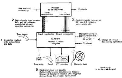
Fig. 6.—SAAB D2 in process control application.
complete conversions per second. Internal reference to the converter is obtained by temperature stabilized zener diodes.
Output digital-analog converters can deliver + 1 0 V with an error of 0.05 per cent of full scale. The conversion time is 5 μ$.
A paper tape reader is used for feeding the computer with instructions and data. A tape punch and a typewriter are used for digital information read out. The computer is also equipped with a separate panel for display
ing numeric characters.
U S E O F I N P U T A N D O U T P U T F A C I L I T I E S
In Fig. 6 is shown how the different types of input and output facilities of the computer are used in a typical process control application.
The computer is loaded with instructions and data supplied by a paper tape reader (1). Signals of different kinds are fed from data transducers in the process to the computer where they are all converted to fit the computer (2). Some of these signals can be priority graded. After computation in the computer, output control information is again converted and transferred as control signals to the process (3). The signal lines (2) and (3) are the main communication channels between the process and the computer.
It is often necessary to change certain constants in the control program during operation (4). This change is made with the aid of the program interrupt transfer control which breaks the main program and storages the new constants in the computer. A manually operated keyboard is used for inserting data in decimal form and a teletyper for submitting signals from telecommunication lines.
Different types of readout equipments are used (5). Results from regularly repeated test programs that checks the central computer with its input and output channels are printed on a typewriter or a paper punch. Statistically treated results from the process, e.g. the quality varia
tion of a product, are read out on an xj>-recorder. The magnetic tape system is used for the storage of process data for later examination. In special types of applications which need large volumes of data for the calculations, the magnetic tape is also used as the main storage.
P O W E R S U P P L Y S Y S T E M
The power supply is equipped with regulation circuits for all supply volta
ges, stabilized by means of a primary zener reference. The supply system is protected against voltage transients from the main 220 V A . C . line. The tran
sistors are also protected by limiting circuits against excessive voltages through failures in the regulation system. Memory loss of information during accidental power failure or while switching the computer on and off, for example, is prevented by blocking the memory circuits at the end of a timing cycle if power failure is indicated.
C I R C U I T R Y D E T A I L S
The transistors used in most of the logical circuits of the computer are of the micro alloy type (2N393). They are directly coupled with a series base resistor, a speed-up capacitor and a reversing resistor. The temperature variation and data spread of the active and passive components have been examined. Out from this, the transistor circuits have been marginal designed according to the worst possible combination of the component tolerances.
The temperature range of reliable operation is — 20°C to +60°C.
A transistor with the three base circuit components, excepting the collector resistor, has been assembled in a moulded block. The components are connected by spot welding. Such a configuration is called a "unit circuit".
A few typical unit circuits for different circuit applications are used as the fundamental building elements that form the logical circuits of the com
puter. They are pre-assembled and treated as components both in the logical design and during manufacturing of the computer (Fig. 7).
In Fig. 8 is shown the symbol of a unit circuit and the application of it to a register position with input channels and buffered output. Information F and F to the register transistors Q1 and Q2 is set by applying a short clock pulse to the bottom transistor Q5 of the input chain Q3 and β4. The infor
mation is then available at the buffer transistors Q6 and Q7.
In the memory circuits and in some parts of the input and output units
Fig. 7. Fig. 8.
f pre-ass<
Fig. 8.—Application of a unit circuit in a register with input and output channels.
Fig. 7.—Photo of pre-assembled unit circuits formed by one transistor, one capacitor, and two resistors.
where the transistor dissipation is of the order of 50 m W , alloyed transistors of the type 2N317 (pnp) and 2N358 (npn) are used. In circuits with high current drain, e.g. in the memory system a pnp transistor is combined with a npn type to form a current economical circuit.
The question of reliability has been considered during the design and manufacture of the computer. A l l components have been chosen after environmental tests. The temperature range of the individual unit circuits,
— 20°C to +60°C, gives large working margins of the computer within more limited operating conditions.
T E C H N I C A L F E A T U R E S
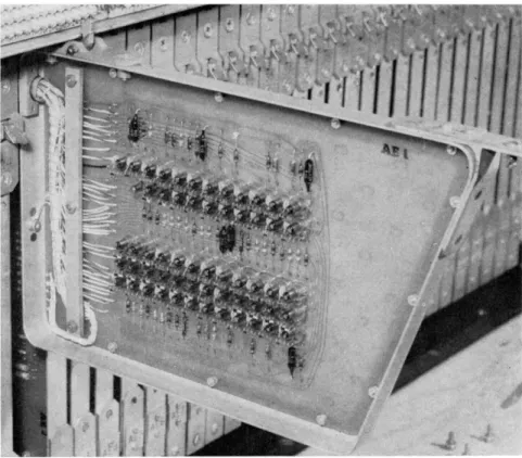
The computer is completely transistorized. Around 6000 transistors and 3500 diodes are used in the machine. A l l unit circuits and other passive components as diodes, chokes, and decoupling capacitors are mounted on printed circuit cards placed in two rows within the machine. T o obtain highest reliability, connectors within the machine have been avoided and all cards are permanently soldered to the wiring. For servicing, each card can be swung out so that both sides of it become accessible (Fig. 9).
Fig. 9.—Photo of printed circuit card containing unit circuits and other components.
Note the wiring soldered directly to the machine.
Within the cabinet of the central computer are located the following functional sub-units: arithmetic unit; control unit; data store; instruction store; input and output unit including channel selectors, conversion units and logical circuits for tape reader, punch and writer; power supply unit;
control panel.
The control panel of the computer is fitted with all necessary controls for operation and service. Above the control panel are meters and controls for the power system. The computer is designed for table-top operation. N o additional arrangements for cooling or for room air-conditioning are necessary when working at normal room conditions.