MM Science Journal | www.mmscience.eu ISSN 1803-1269 (Print) | ISSN 1805-0476 (Online)
Special Issue | HSM 2021
16th International Conference on High Speed Machining October 26-27, 2021, Darmstadt, Germany DOI: 10.17973/MMSJ.2021_11_2021170
HSM2021-2021170
DYNAMIC CHARACTERIZATION OF MILLING BASED ON INTERRUPTED FEED MOTION
Adam K. Kiss1,2*, D. Bachrathy1,2
1MTA-BME Lendulet Machine Tool Vibration Research Group, Department of Applied Mechanics, Budapest University of Technology and Economics, Budapest H-1521, Hungary
2Department of Applied Mechanics, Budapest University of Technology and Economics, Budapest H-1111, Hungary
*Corresponding author; e-mail: kiss_a@mm.bme.hu
Abstract
This study presents an experimental method for detecting and avoiding chatter vibrations that occur during general milling processes. The main idea is to capture the so-called dominant spectral properties from the transient vibrations of the milling process, which gives a good approximation for its dynamical behavior and provides a quantitative measure of stability. To induce transient vibration, the machining process is momentarily interrupted. Therefore, the method offers the possibility that the stability limit can be forecasted by extrapolation from stable and accurate measurement points without reaching harmful vibration on the machine tool. We present laboratory tests with momentary interrupted straight tool path to demonstrate the applicability of the proposed method.
Keywords:
milling; stability; chatter detection; Floquet multiplier
1 INTRODUCTION
In mass production, maximizing productivity and optimizing the production process are essential tasks in achieving market competitiveness. However, it is not always possible to fully exploit the power potentials of the machining, such as turning and milling operations. One probable cause of these limiting factors is machine tool vibrations [Munoa 2016]. Thus, a significant engineering problem is a thorough study of these vibrations during which it is possible to ensure reliable prediction of their propagation.
One of the most widely used methods to avoid harmful vibrations is to set the machining parameters based on the so-called stability lobe diagram [Altintas 2012], which separates the preferred stable and non-preferred unstable operations in the space of technological parameters. The calculation of these maps is based on the mathematical and mechanical model describing the milling process [Tlusty 1954, Tobias 1965]. The inherent surface regeneration effect is described in the milling process by periodic delay- differential equations [Stepan 1989], which linear stability property is determined by the so-called Floquet theory [Farkas 1994]. However, modeling uncertainties may occur during the model creation, which may reduce the reliable applicability of the stability maps [Hajdu 2020].
Several numerical methods have been developed for experimental chatter identification in the last decades, which often does not require stability lobe calculations [Altintas 1992, Kuljanic 2008, Honeycutt 2016, Quintana
2011]. However, usually, these techniques rely on a so- called chatter indicator metric, which can be different for each method, and the critical level of the indicator is usually empirically defined. To overcome these difficulties and unify the different chatter indicator metrics, we proposed to use the modulus of the dominant Floquet multiplier as chatter indicator [Kiss 2018], which is based on the stability theory behind the milling operation. The method can provide a quantitative measure of stability based on measured vibrations [Mann 2006]. To distinguish the primary motivation compared to classical chatter indicators, as long as classical methods can indicate the occurrence of chatter after their appearance, contrary, the method presented here can preliminary determines how distant are the stability borders when cutting parameters are varied, which allows indirect estimation of the stability borders. Similarly to other chatter detection methods, this characterization of the dynamical behavior makes identifying any additional system parameter unnecessary and requires no exact stability lobe calculation. The main idea of the operational stability prediction is to approximate the Floquet multipliers of the corresponding mechanical system based on its transient vibration during the machining [Kiss 2017, Kiss 2020]. However, inducing transient vibration may be challenging during the machining operation. The method is based on the investigation of the transient vibrations, which are generated by operational impact tests (hammer blow).
In-process impulse excitation for induce the transient vibration is an already used method in the literature [Murphy
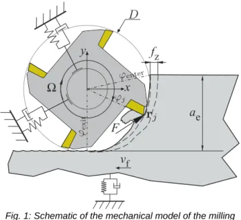
Fig. 1: Schematic of the mechanical model of the milling process.
1994, Mann 2006, Little 2020]. However, it has the drawback that it requires additional perturbation during the milling operation. This in-process perturbation is usually performed by human experts with hammer blow, however, it has drawbacks. A ball shooter device [Takács 2018] can eliminate many of its disadvantages, which is well automated, has high repeatability capabilities, and can even be used for modal testing, also [Bachrathy 2020].
Another method to analyze the transient vibrations is the operational modal analysis (OMA), which was first applied and investigated to estimate the stability of turning process in [Kim 2019]. For industrial applicability, it may be necessary to integrate the perturbation process into the machining operation and avoid any external intervention such as hammer blow.
In this paper, we attempt to induce transient vibrations by minimally modifying the machining process instead of human perturbation (hammer blow). The key idea is to interrupt the feed movement of the milling process for a moment and enters into the material again, thereby achieve significant transient vibration that can be used to identify the cutting process. Note that there must be a permanent cutting process to determine stability; however, if the tool enters the workpiece slowly, there is enough time for the vibration signal to develop, and no proper transient vibration is generated. To demonstrate the effectiveness of these feed movement interruptions, we illustrate their applicability with three different entry cases.
The rest of the paper is organized as follows. First, in Sec.
2, the mechanical model is introduced. In Sec. 3, we demonstrate the effects of the three different tool entry cases by numerical simulations and experimental tests.
Then, in Sec. 4. the efficiency of the method is presented through a real case study. Finally, in Sec. 5, we conclude our results and discuss future directions.
2 MECHANICAL MODEL OF MILLING
The dynamical model presented in this section is based on the experimental setup (see Fig. 1), which is discussed later in Sec. 4. The equation of motion expressed in the modal space using the modal coordinate vector 𝐪(𝑡) ∈ ℝ𝑑 with 𝑑 number of degrees of freedom (DOF) forms
𝐪̈(𝑡) + [2ζ𝑘ωn,𝑘]𝐪̇(𝑡) + [ωn,𝑘2 ]𝐪(𝑡) = 𝐔⊤𝐅(𝑡), (1)
where ζ𝑘 is the relative damping ratio, ωn,𝑘 is the natural angular frequency, 𝐔 = [⋯ 𝑐𝑘𝐏𝑘 ⋯] is the mass normalized modal transformation matrix with mode shape vector 𝐏𝑘 and 𝐅(𝑡) is the resultant cutting force. The normalization parameter is defined by 𝑐𝑘= 𝜔n,𝑘(𝑘𝑘𝐏𝑘⊤𝐏𝑘)−1/2, where 𝑘𝑘 is the modal stiffness [Dombovari 2010]. The regenerative cutting force for simple helical milling tools with 𝑍 number of cutting edges, lead angle 𝜅 and uniform helix angle 𝜂 has the form [Altintas 2012]
𝐅(𝑡) = − ∑ ∫ 𝑔(𝜑𝑍0 0𝑎p 𝑗)(𝐓(𝜑𝑗) (𝐊e+ (𝐊c⨂𝐧(𝜑𝑗)) (𝐔Δ𝐪(𝑡, 𝑡 − 𝜏) + 𝑓𝑍𝐞𝑥))) 𝑑𝑧
cos 𝜂 sin 𝜅, (2) where 𝑎p is the axial depth of cut, 𝑓𝑍 is the feed per tooth 𝐊e and 𝐊c= [𝐾t 𝐾r 𝐾a]⊤ collect the edge coefficients and cutting coefficients, respectively. The angular position 𝜑𝑗 of the 𝑗th cutting edge along the axial direction 𝑧 reads 𝜑𝑗(𝑡, 𝑧) =2𝜋𝑛
60 +2𝜋𝑗
𝑍 − 𝑧2
𝐷tan 𝜂 where 𝑛 is the spindle speed in rpm and 𝐷 is the tool diameter. The regenerative effect appears in Δ𝐪(𝑡, 𝑡 − 𝜏) = 𝐪(𝑡 − 𝜏) − 𝐪(𝑡), where the regenerative time delay is 𝜏 = 60/(𝑛𝑍). The transformation matrix 𝐓 and the normal vector 𝐧 can be found in [Dombovari 2010]. The so-called screen function 𝑔 indicates that the 𝑗th edge is in contact with the material between the enter 𝜑enter and exit angle 𝜑exit only
𝑔(𝜑) = {1 if 𝜑enter< 𝜑 < 𝜑exit,
0 otherwise. (3)
These angles are the nonlinear functions of the actual radial depth of cut 𝑎e, reads as
𝜑enter= {
0 if up-milling, arccos (2𝑎e
𝐷 − 1) if down-milling, 𝜑exit= {arccos (1 −2𝑎e
𝐷) if up-milling,
𝜋 if down-milling. (4)
Noted that this radial depth of cut is usually considered constant during the cutting process, however, at the beginning of the cutting operation when the cutting tool enters into the workpiece, the radial depth of cut is continuously formed resulting as a slowly changing parameter [Dombovari 2018]. Here, slowly means that its changing is relatively slower than the machine tool's dynamic behavior. In order to induce a sufficient transient vibration without any external perturbation, thus identifying and quantifying the behavior of the milling process, the tool entry must be investigated in detail.
3 OPERATIONAL STABILITY PREDICTION 3.1 Stability measure
The main idea is to capture the dominant spectral properties of the machining operation, which is carried by the transient vibration components. In this way, we calculate the Floquet multipliers (characteristic multiplier) of the underlying system, consequently, we characterize the stability properties of the milling process. This is usually referred to in the literature as reduced-order modelling, when one approximates a complex physical system with a finite-dimensional one that captures its dominant behavior.
For this task, here, we use the so-called dynamic mode decomposition (DMD) method [Schmid 2010], which can approximate the system matrix (see detailed description in
Fig. 2: schematics of the different tool entries. (C1) represents the slowly varying tool entry which is prepared with a ramp. (C2) shows a traditional entry without any preparation, where the CWE builds up in a special way. (C3) shows the
proposed tool entry, where there is an abrupt change in the parameters.
Fig. 3: Schematic figure and setup for the experimental system [Kiss 2018].
[Tu 2014]). The basic concept of the DMD method is to build up a linear map by selecting and ordering relevant parts of the measured vibration signal and it can provide the solution in linear least square sense. Here, we apply the DMD method on the transient vibration component of the milling process and approximate the monodromy matrix, which spectral radius describes a measure of stability.
3.2 Triggering transient vibration
In this subsection, we present and investigate the effect of the entry of the tool along its path into the workpiece and the resulting transient vibrations in three different cases.
During all cases, the tool moves along a straight path in order to keep the model as simple as possible while keeping the essential core of the dynamic behavior.
The first case (C1) is a conventional tool entry where the tool penetrates an intact surface. This is the most common case during the beginning of any machining process. Here, the entry and exit angles are continuously built up as the tool enters into the workpiece completely (see the middle panel in Fig. 2), providing a slowly changing cutter workpiece engagement (CWE). In this case, the enter and exit angles during the slow varying domain (𝑥 < 𝐷/2) forms
𝜑̃enter= { 𝜋
2− 𝛼 if up-milling, max {𝜋
2− 𝛼, 𝜑enter} if down-milling,
𝜑̃exit= {min {𝜋
2+ 𝛼, 𝜑exit} if up-milling,
𝜋
2+ 𝛼 if down-milling. (5) where 𝛼 = arccos (1 −2𝑥
𝐷) and 𝑥 is the tool path coordinate measured from the edge of the workpiece (see Fig. 2).
Compared to this general case, we apply two additional extreme cases.
One where the tool entry and the total depth of cut build up even more slowly than compared to the traditional entry (C2). In this case, the tool entry is prepared with modified workpiece geometry: a ramp with length 𝑙, as shown in the left panel in Fig. 2. In this case the actual depth of cut can be given by
𝑎̃e(𝑥) = {
𝑎e
𝑙 𝑥 𝑥 < 𝑙,
𝑎e 𝑥 ≥ 𝑙, (6)
Tab. 1: Technological parameters.
Tab. 2: Modal and cutting parameters.
and the actual enter and exit angles can be calculated based on Eqs. (4).
In the other extreme case (C3), the workpiece is prepared by forming the profile of the workpiece with the negative profile of the cutting tool (see schematic in the right panel in Fig. 2). This is achieved by pre-milling the workpiece so that no change in the radial depth of cut occurs at the tool entry 𝑎̃e(𝑥) = 𝑎e for all 𝑥, and the machining takes place immediately with 𝑎e radial depth of cut at the same time. In this case, the tool entry can be considered a sudden jump (unit step) in which all slow dynamic changes have been eliminated. The tool entry for the three different cases and the resulting transient vibrations are first examined and discussed by numerical simulation and then laboratory tests in the following sections.
3.3 Numerical simulation
The experimental procedure is presented for down-milling operation with a 2-fluted endmill. The machined workpiece is clamped onto the top of a flexure [Bayly 2002, Ransom 2016, Munoa 2020], which was designed to mimic the dynamics of a single-degree-of-freedom system, see in Fig.
3 [Kiss 2018]. The numerical simulations were performed for the three different tool entry strategies (C1 – C3) while
Parameter Symbol Value
spindle speed 𝑛 6000 rpm
axial depth of cut 𝑎p 0.5 mm
radial depth of cut 𝑎e 8 mm
feed per tooth 𝑓𝑍 0.05 mm
ramp length 𝑙 32 mm
number of edges 𝑍 2
tool diameter 𝐷 16 mm
helix angle 𝜂 30°
rake angle 𝜅 90°
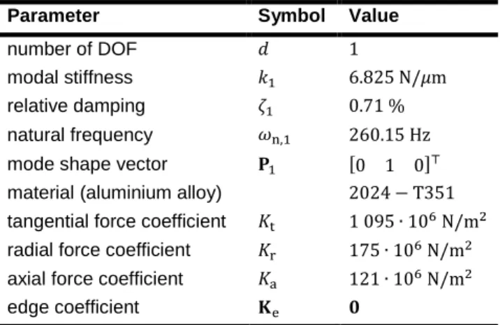
Parameter Symbol Value
number of DOF 𝑑 1
modal stiffness 𝑘1 6.825 N/𝜇m
relative damping 𝜁1 0.71 %
natural frequency 𝜔n,1 260.15 Hz
mode shape vector 𝐏1 [0 1 0]⊤
material (aluminium alloy) 2024 − T351 tangential force coefficient 𝐾t 1 095 ∙ 106 N/m2 radial force coefficient 𝐾r 175 ∙ 106 N/m2 axial force coefficient 𝐾a 121 ∙ 106 N/m2
edge coefficient 𝐊e 𝟎
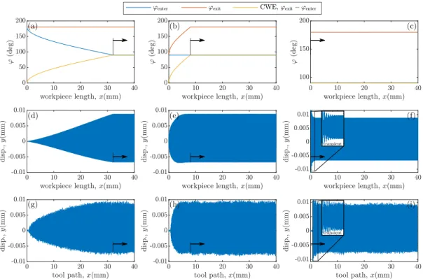
Fig. 4: Results of the different tool entry strategies. Top row contains the enter and exit angles together with the CWE as a function of the tool position, the middle row shows the simulation results, while the bottom row visualizes the
corresponding measurement results.
all the other parameters were fixed. The used technological parameters of the milling operation are presented in Table 1. For the numerical simulations, the modal parameters and the cutting force parameters – which were identified by modal analysis and cutting tests – can be found in Table 2.
The results are shown in the panels of Figure 4. The left column (panels a,d,g) of the figure visualizes the results of the smoothed, ramp-like tool entry (C2), the middle column (panels b,e,h) shows the normal tool entry (C1), while the right column (panels c,f,i) presents the tool entry with prepared workpiece profile (C3). In the panels of the top row (panels a,b,c), the entry and exit angles and the CWE along the toolpath are plotted, in the middle row (panels def) the numerical simulations are presented and in the bottom row (panels g,h,i) the corresponding measurement results are shown, which will be detailed in the next section.
From the top panels one can clearly identify the position where the total radial depth of cut is built up (whose starting point is marked with black arrows). The stability properties can be associated with the stationary process after this point only, and from which the vibration signals can be used for the DMD method. However, as expected, it is clear from the vibration time signals that no transient vibrations are observed during the ramp-like (C2) and the normal tool entry strategies (C1). That is because the technological parameters are changing slowly relative to dynamical behaviour so that the system can follow the changes without any significant overshoot. This occurs since the state is quite close to the non-stationary vibration during the slowly changing domain. The only case where transient vibration can be experienced is the proposed tool entry (C3), when the milling process starts with full radial depth of cut from the beginning. In this case, a significant transient oscillation is generated, from which the characteristic multipliers can be approximated using the DMD method described in Sec. 3.1.
3.4 Experimental validation
These demonstrative cases are also validated by experimental tests. During the experiment, the tool was attached to a spindle adapter BT30 ER16 on a three-axis NCT EMR-610MS machine tool. The response of the flexure was acquired by NI cDAQ-9178 Chassis with NI 9234 Module at 52 kHz sampling rate and PCB 352C23 type acceleration sensor. To analyse the displacement signal, double integration in frequency domain was used together with an appropriate high-pass filter with cutoff frequency of 50 Hz. The time signals of the displacement are plotted in Fig. 4 g,h,i. One can clearly see that the vibration amplitudes are almost identical for the numerical and experimental tests, which support the fitted parameters in Table 2. The only deviation in the vibration amplitude can be found during the beginning of case C2, which is mainly resulted from the mismatches of the cutting force edge coefficient.
The results of the numerical simulations and the measurements also support that a suitable transient vibration can be formed with the proposed interrupted tool motion, which leads to the prepared tool entry (C3), from which the stability properties of the milling process can be determined. Consequently, we use this type of tool entry to induce transient part for the operational stability prediction.
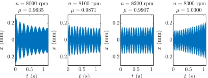
4 MOMENTARILY INTERRUPTED CUTTING In this section, the above-described measurement technique is applied in case studies with the proposed tool entry where the dominant characteristic multiplier is determined for a set of spindle speeds 𝑛 = [8000, 8100, 8200, 8300] rpm and axial depth of cut 𝑎p= 1.5 mm. The proposed tool entry can be done by momentary stop the feed movement assuming that the machine tool can accelerate to the desired feed rate again. During the cutting
Fig. 5: Time profiles and the fitted characteristic multipliers for the experimental tests with different spindle speeds.
tests, we went minimally backward along the toolpath after the stop ensure enough distance to accelerate to the feed velocity.
The goal is to increase cutting productivity while the machining remains stable, achieve high material removal rate while keeping the technological parameters in an acceptable range without reaching chatter vibration. For the experiment, we first selected an operational point with spindle speed 𝑛 = 8000 rpm. In this working point, the milling process was stable, which can be seen as a decreasing transient vibration in the left panel of Fig. 5.
Also, the value of the calculated dominant multiplier is less than one (𝜇 = 0.9635).
Subsequently, we optimized the machining process by increasing the material removal rate, thus increasing the spindle speed in 100 rpm increments. In this case, the milling process became unstable at spindle speed 𝑛 = 8300 rpm, as it can be seen by increasing vibration amplitude in the time profiles. This tendency was also followed by the values of the fitted multipliers (see the numerical values above the time profiles in Fig. 5). Based on the first three fitted multipliers, we could also predict the chatter before evaluating the last measurement.
During our laboratory tests, the tool entry generated sufficient transient to identify Floquet multipliers in all cases.
However, in a real milling environment, one drawback of the method may be that in some cases the transient vibration dies out quickly. One reason for this is that the associated decay ratio is high, which means that the stability limit is far.
However, it may also mean that the "perturbation" resulting from the tool entry is not sufficient to excite the corresponding critical modes. Therefore, creating the proper excitation and measuring accurate response signal are also significant tasks in operational stability prediction, as in the field of modal analysis.
5 SUMMARY
The present work shows that the proposed interrupted tool motion is suitable for determining the stability properties during the milling operation. The prepared tool entry is suitable for sufficiently perturb the system, consequently, combining with the DMD method, it is capable of capturing the ‘measure’ of stability based on the measured response only. These results support the technology design to identify those parameters where the milling process is stable, thus, providing a proof of concept for an automatic unmanned expert monitoring system.
As benefit, a machine tool can complete the proposed process quickly because it is enough to stop for just a moment, therefore the process does not involve significant machine time on its own. Another advantage of the proposed method is that it does not require any external equipments for the excitation that are typical for modal analysis.
As presented, the method works well on the flexible workpiece holder, however, many more tests need to be performed in different real industrial environments in further investigations.
6 ACKNOWLEDGMENTS
This paper was supported by the Hungarian Scientific Research Fund OTKA FK-124462. The research reported in this paper and carried out at BME has been supported by the NRDI Fund (TKP2020 NC, Grant No. BME-NC) based on the charter of bolster issued by the NRDI Office under the auspices of the Ministry for Innovation and Technology.
7 REFERENCES
[Munoa 2016] Munoa, J., Beudaert, X., Dombovari, Z., Altintas, Y., Budak, E., Brecher, C., Stepan, G. Chatter suppression techniques in metal cutting, CIRP annals, 2016, 65 (2):785–808.
[Altintas 2012], Altintas, Y. Manufacturing Automation - Metal Cutting Mechanics, Machine Tool Vibrations and CNC Design, Second Edition, Cambridge University Press, Cambridge, 2012
[Tlusty 1954] Tlusty, J., Spacek, L. Self-excited vibrations on machine tools, Nakl. CSAV, Prague. in Czech., 1954.
[Tobias 1965] Tobias, S. Machine-tool Vibration, J. Wiley, Blackie, Glasgow, 1965.
[Stepan 1989] Stepan, G. Retarded dynamical systems, Longman, Harlow, 1989
[Farkas 1994] Farkas, M. Periodic motions, Vol. 104, Springer-Verlag, New York, 1994
[Hajdu 2020] Hajdu, D., Borgioli, F., Michiels, W., Insperger, T., Stepan, G, Robust stability of milling operations based on pseudospectral approach, International Journal of Machine Tools and Manufacture 149 (2020) 103516.
[Altintas 1992] Altintas, Y., Chan, P. K. In-process detection and suppression of chatter in milling, International Journal of Machine Tools and Manufacture, 1992, 32(3):329–347.
[Kuljanic 2008] Kuljanic, E., Sortino, M., Totis, G.
Multisensor approaches for chatter detection in milling, Journal of Sound and Vibration, 2008, 312:672–693.
[Honeycutt 2016] Honeycutt, A., Schmitz, T. L. A new metric for automated stability identification in time domain milling simulation, Journal of Manufacturing Science and Engineering 2016, 138:074501
[Quintana 2011] Quintana, G., Ciurana, J. Chatter in machining processes: A review, International Journal of Machine Tools and Manufacture, 2011, 51:363–376.
[Kiss 2018] Kiss, A. K., Hajdu, D., Bachrathy, D., Stepan, G. Operational stability prediction in milling based on impact tests, Mechanical Systems and Signal Processing, 2018, 103:327–339.
[Mann 2006] Mann, B. P., Young, K. A. An empirical approach for delayed oscillator stability and parametric identification, Proceedings of the Royal Society A, 2006, 462: 2145–2160.
[Kiss 2017] Kiss, A. K., Bachrathy, D., Stepan, G.
Experimental determination of dominant multipliers in milling process by means of homogeneous coordinate transformation, International Design Engineering Technical Conferences and Computers and Information in Engineering Conference, Vol. 58226, American Society of Mechanical Engineers, 2017, p. V008T12A053.
[Kiss 2020] Kiss, A. K., Bachrathy, D., Dombovari, Z.
Parameter identification of periodic systems by impulse dynamic subspace description, 10th European Nonlinear Dynamics Conference (ENOC 2020), Lyon, France, 2020 [Murphy 1994] K. D. Murphy, P. V. Bayly, L. N. Virgin, J. A.
Gottwald, Measuring the stability of periodic attractors using perturbation-induced transients: Applications to two non- linear oscillators, Journal of Sound and Vibration, 1994, 172 85–102.
[Little 2020] Little, J. A., Turner, J. D., Mann, B. P. Improving empirical characteristic multiplier estimation through a change of basis, Journal of Sound and Vibration, 2020, 115613.
[Takács 2018] Takács, D., Wohlfart R., Miklós, Á., Krajnyák, G., Tóth, A., Stépán, G. Ball shooting tests for identification of modal parameter variation in rotating main spindles.
Procedia CIRP, 2018, 77, 481–484.
[Bachrathy 2020] Bachrathy, D., Kiss, A. K., Kossa, A., Berezvai, S., Hajdu, D., Stepan, G. In-Process Monitoring of Changing Dynamics of a Thin-Walled Component During Milling Operation by Ball Shooter Excitation. Journal of Manufacturing and Materials Processing. 2020; 4(3):78.
[Kim 2019] Kim, S., Ahmadi K. Estimation of vibration stability in turning using operational modal analysis, Mechanical Systems and Signal Processing 2019, 130 315–332.
[Dombovari 2010] Dombovari, Z., Altintas, Y., Stepan, G.
The effect of serration on mechanics and stability of milling cutters, International Journal of Machine Tools and Manufacture, 2010, 50(6):511–520.
[Dombovari 2018] Dombovari, Z., Munoa, J., Kuske, R., Stepan, G. Milling stability for slowly varying parameters, Procedia CIRP, 2018, 77:110 – 113, 8th CIRP Conference on High Performance Cutting (HPC 2018)
[Schmid 2010] Schmid, P. J. Dynamic mode decomposition of numerical and experimental data, Journal of fluid mechanics 656, 2010, 5–28.
[Tu 2014] Tu, J. H., Rowley, C. W., Luchtenburg, D. M., Brunton, S. L., Kutz, J. N. On dynamic mode decomposition: Theory and applications, Journal of Computational Dynamics, 2014, 1(2):391–421
[Bayly 2002] Bayly, P. V., Mann, B. P., Schmitz, T. L., Peters, D. A., Stepan, G., Insperger, T. Effects of radial immersion and cutting direction on chatter instability in end- milling, ASME International Mechanical Engineering Congress and Exposition, 2002, Vol. 3641:351–363.
[Ransom 2016] Ransom, T., Honeycutt, A., Schmitz, T. A new tunable dynamics platform for milling experiments, Precision Engineering, 2016, 44:252–256.
[Munoa 2020] Munoa, J., Sanz-Calle, M., Dombovari, Z., Iglesias, A., Pena-Barrio, J., Stepan G. Tuneable clamping table for chatter avoidance in thin-walled part milling, CIRP Annals, 2020, 69(1):313–316.
[Dombovari 2021] Dombovari, Z. Stability properties of regenerative cutting processes, based on impulse response functions expressed in the impulse dynamic subspace, International Journal of Machine Tools and Manufacture 162 (2021) 103691.
[Sykora 2021] Sykora, H. T., Hajdu, D., Dombovari, Z., Bachrathy, D. Chatter formation during milling due to stochastic noise-induced resonance, Mechanical Systems and Signal Processing, 2021, 161:107987.