CHAPTER 3
Impeller Characteristics and Power
Robert L. Bates, Philip L. Fondy, and John G. Fenic Chemineer, Inc., Dayton, Ohio
I. Introduction H 2
II. Impeller Description I1 2
A. Propellers H3
B. Turbines 4 n
C. Paddles 1 16
D . High Shear Impellers U 8 E. Reciprocating Impellers 118
III. Power Theory 1 19
A. Historical 119 B. Dimensional Analysis 120
C. Use of Equations Developed for Correlation of Data 124
IV. Power Correlations 128 A. Propellers · 128
B. Turbines I3 2
C. Paddles 9 ! 3
D . High Shear Impellers 143 V. Fluid Property Effects 144
A. Two-Phase Fluids 144 B. Non-Newtonian Fluids 148 VI. Flow Pattern and Power 152
A. Eccentric Mounting 153
B. Baffles I5 6
C. Draft Tubes · 159
D . Geometry Baffling 159
E. Flow Rate I5 9
F. Starting Torque · I6 0
VII. Impeller and Process Power Selection 160
A. Impeller Selection : I6 0
B. Process Power Selection · 164
VIII. Agitator Drives for Experimental Use 168
A. Drive Selection 16 8
B. Power Measurement 170
IX. Future Needs 2 i 7
List of Symbols 4 i7
References 176 111
112 Robert L. Bates, Philip L. Fondy, and John G. Fenic I. Introduction
The.scope and volume of published literature on agitator impeller power available for study and correlation has assumed awesome proportions in re- cent years. It would be most convenient, in writing this chapter, simply to set forth abstracts of the more prominent available data. But this would certainly compound confusion, for many of the works are so conflicting in viewpoint as to be somewhat uninstructive. The temptation with subject matter of this sort is to confine the scope in some arbitrary manner to just the areas where agree- ment is good—thus avoiding confusion and controversy—but this would scarcely act as a stimulant for further work.
Prior to discussing power we must first define impeller charcteristics and establish nomenclature. A classification of impeller types will be presented based partly on physical form and partly on category of operation. As dimen- sional analysis provides a sound basis of correlation a complete section is devoted to the development and interpretation of the important relationships.
Power correlations are presented covering a multitude of impeller and vessel configurations with a wide range of fluid properties. The discussion of power in this chapter, however, is not to be construed as implying that power can ever be a sole criterion for determining the extent of mixing accomplished.
A section is therefore included to outline the basic principles of impeller and process selection and serve as an introduction to more detailed discussion in later chapters. Finally, as an aid to experimenters, a section is included on the mechanical design of small-scale agitator drive assemblies.
II. Impeller Description
It is often stated that any impeller can be adjusted in performance to handle a given j o b — b u t such a generality ignores good engineering practice which demands economy. On the other hand, the core of truth in the statement does serve to emphasize the importance of understanding the performance of the basic types. Only in this way can the variables of selection and application be evaluated.
Little attempt has been made in the published literature to present data on impellers or processes by reduction to basic performance categories. Some use has been made of the knowledge of the existence of the distinct areas of laminar and turbulent flow but usually only to show the action of a particular impeller—often to disadvantage. The fact that any impeller can be adjusted in design to vary the balance of flow and head can often be utilized to advan- tage for characterizing impeller action, but it is not a generally useful method for classification. It is also possible to group impellers by peripheral speed since the three c o m m o n types—propeller, turbine, and paddle—normally fall into distinct ranges, b u t again this is a somewhat terse classification.
Traditionally impellers have been classified by physical form although numer- ous conflicts of nomenclature have developed.
It develops naturally that some impeller types are best described by physical form and others by their category of operation. The multitude of impeller configurations can be grouped into five distinct categories, of which only the first four are of commercial importance.
A. PROPELLERS
Essentially high-speed impellers of the axial flow-type (discharge flow parallel to the agitator shaft) propellers may be used in low viscosity liquids almost without restriction as to the size and shape of the vessel. The circulat- ing capacity is high and, as with a jet, entrainment of surrounding liquid occurs. Circulation rate is very sensitive to an imposed head and care must be exercised when applying propellers to a draft tube or circulating p u m p system.
1. Design
The modified marine-type propeller is in almost universal use today in the three-blade style. Older literature treats the two- and four-blade style and a few current applications (such as pulp stock agitation) still use special four- blade designs. But no real case for other than the three-blade style has been made since F r o u d e (F5) in 1886 stated he is "inclined to think . . . not much to choose between 2, 3, and 4-bladed screws . . . " Total blade area is usually stated as the ratio of developed or projected area to disk area and typical values range from 0.45 to 0.55. It should be noted that the driving or operat- ing face of a blade is flat or concave while the back side is convex.
2. Pitch
Individual blade slope varies continuously from root to tip but specification of pitch of a propeller is on the basis of its being a segment of a screw. Pitch is the advance per revolution. In general, industry has standardized on a
" s q u a r e " pitch, i.e., a pitch value equal to the diameter. When an odd pitch is used it is stated as the second term, such as 8 χ 12 in. for a 1 J: l pitch.
3. Hand
Definition of the way the blades are pitched is related to a viewpoint and direction of rotation. Marine practice derives from screw thread nomenclature and defines a left-hand propeller as one which thrusts the fluid downward when rotating clockwise viewed from above. Conversely, a right-hand propeller would thrust upward under the same operating conditions. This definition will be used throughout this text where pitched impellers are described. U n - fortunately, not all manufacturers of propeller agitators have standardized on this designation.
114
B. TURBINES
The term " t u r b i n e " has been applied t o a wide variety of impellers without regard t o design, direction of discharge, or character of flow. T h e A.I.Ch.E.
" S t a n d a r d Test Procedure for Impeller-Type Mixing E q u i p m e n t " (A3) de- fines a turbine as " a n impeller with essentially constant blade angle with re- spect t o a vertical-plane, over its entire length or over finite sections, having blades either vertical or set at an angle less than 90° with the vertical." Blades may be curved or flat. The number of blades is not important and can be two or more.
There are two basic physical forms of the turbine, the flat-blade radial dis- charging style and the pitched-blade axial thrust type. All others are modifica- tions of these and, in most cases, performance is affected in only a minor way.
Serious alteration of performance must come from changes in geometry.
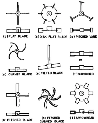
Figure 1 illustrates the conventional turbines and the more popular modi- fications.
a. Flat blade. Also termed a "straight blade turbine," this impeller dis- charges radially, deriving suction from both t o p and bottom. Customary operation is in a peripheral speed range from 600 to 900 ft./min. Blade widths are generally one-fifth t o one-eighth of the diameter.
(a)FLAT BLADE (b)DISK FLAT BLADE (c) PITCHED VANE
B - f F - n
(d) CURVED BLADE ( . ) TILTED BLADE ( f ) SHROUDED
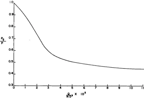
b. Disk flat blade. This turbine is widely used industrially and has been employed in many investigations. While it has essentially the same perform- ance characteristic as the flat-blade turbine, the difference in power consump- tion is marked. This design characteristic will be treated in detail later in the chapter.
c. Pitched vane. This turbine is termed by Brumagin ( B l l ) a "radial p r o - peller' but is simply an adaptation of the disk type with the area reduced by pitching the blades to the vertical plane. Its advantage is the ability to ob- tain a high ratio of DjT and a high speed (for drive economy) without high power consumption. Very little quantitative power or performance data have been published on this impeller. The paper of Y a r h a m and Sigler ( Y l ) con- tains scattered data.
d. Curved blade. Also termed the " b a c k s w e p t " or "retreating b l a d e " tur- bine, the blades curve away from the direction of rotation. This modification of the flat-blade style is commonly thought to reduce the mechanical shear effect at the impeller periphery—industrial usage in suspensions of friable solids is widespread.
e. Tilted blade. Mounting of this turbine is described by Lyons (L4)—
in reference to the curved-blade style as having the effect of increasing the depth of the flow pattern and generally improving performance without in- crease in power, but no quantitative support is given.
/. Shrouded. Addition of a plate, full or partial, to the t o p or b o t t o m planes of a radial flow turbine is made to control the suction and discharge pattern. In Fig. lf the upper unit has annular rings on t o p and bottom. The lower design is fully shrouded on top to restrict suction to the lower side. The impeller used by Cooper et al. (C8) in gas dispersion was this latter style and was called a "vaned disk." A full shroud on the lower surface of an impeller which is located near the liquid surface will increase the vortex considerably e.g., for gas re-entrainment.
g. Pitched blade. This impeller has a constant blade angle over its entire blade length. Its flow characteristic is primarily axial but a radial component exists and can predominate if the impeller is located close to the tank b o t t o m . The blade slope can be anywhere from 0° to 90°, but 45° is the commercial standard. This impeller is also known as a "fan t y p e " and in the early valu- able works of Hixson and Baum (H4) and Miller and M a n n (M10) is labeled a "propeller."
h. Pitched curved blade. Sloping the blades of a curved-blade style to com- bine the effects of Figs. Id and l g is possible and has been practiced occasion- ally. N o performance or power data are available and the high cost of con- struction of this impeller would eliminate it from consideration in all but very special applications.
i. Arrowhead. This mixed flow (axial and radial) impeller was studied by
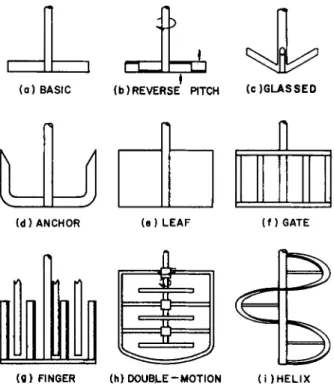
FIG. 2. Paddle impeller designs.
Foust and co-workers (F4) and Olney and Carlson ( 0 4 ) but apparently never achieved commercial significance.
C. PADDLES
The paddle in its basic form holds a fundamental place in industrial mixing practice by virtue of its antiquity of use—although considerable conflict of nomenclature exists. In its basic form a common description would consist of usually two blades, horizontal or vertical, with a high DjT ratio. Actually, by both physical form and power correlation the basic paddle is simply a turbine-type impeller, but-it is worthwhile to retain the distinction for two reasons. First, the bulk of the technical literature treating the basic paddle is based on operation in the laminar range, or in the transi- tion and turbulent range without baffles. Turbine impellers are not normally considered for either of these conditions so, to avoid added confusion, the term " p a d d l e " will be retained in referencing the applicable literature. Second, an impeller of the basic paddle design is not particularly effective for many pro- cess operations involving high viscosities. F o r this reason numerous other impeller configurations have evolved from it. It is thus convenient to consider these designs as a group, as shown in Fig. 2.
3. Impeller Characteristics and Power 117 a. Basic paddle. The simplest form is a single horizontal flat beam. The ratio of impeller diameter to tank diameter is usually in the range of 0.5 to 0.9. The peripheral speed range is generally 250 to 450 ft./min. Paddles used in the United States have generally had ratio of width to diameter (w/D) from one-sixth to one-twelfth, but European practice is in the neighborhood of one-fourth to one-sixth.
b. Reverse pitch. To improve the top-to-bottom turnover characteristic of a simple paddle, the reverse pitch design in Fig. 2b is used. The 45° blade angle is reversed at a diameter of approximately three-fourths of the im- peller diameter and rotation is generally set to produce up-flow in the outer section.
c. Glassed steel. This impeller is the three-blade style common in glass- coated vessel applications. Blade form is either a pitch of about 30° from the vertical, or curved. Usually, DjT is from 0.55 to 0.65. In many instances in low viscosity fluids its operation is definitely in the turbine category, but the difficulty of achieving a fully baffled condition in a glass-lined vessel causes it to perform like a paddle in many cases.
d. Anchor. Contouring a simple paddle to the shape of a tank bottom gives the anchor or "horseshoe" style. Extent of the blade may be limited to the lower vessel tangent line or the blades may continue upward along the straight side. Clearance between blade and vessel shell may be from \ to 3 in., depending on tank diameter and heat transfer needs.
e. Leaf. An extreme w/D ratio for a paddle, this geometry occurs frequent- ly in European practice. This design and many other unusual shapes are well described in a publication of Société Auxiliaire d'Industrie (M 13).
/. Gate. A multiple arm paddle with connecting vertical members, this de- sign is often adopted for structural reasons in large tanks.
g. Finger. Also known as a "paste mixer," this combination of vertical blades meshing with stationary baffles has been in use for many years but no data on power or performance have been published. The application is re- stricted to small batch sizes (less than 1000 gal.) because of structural design difficulties.
h. Double-motion. Here, a gate and anchor and a multiple-pitched paddle are combined. Rotation of the two assemblies is countercurrent. Since a special drive with concentric counterrotating output shafts is required, use of this paddle is restricted to a few problems requiring intensive mixing of very vis- cous or very non-Newtonian fluids.
i. Helix. By physical form this configuration least resembles the basic paddle. It does, however, operate in the laminar range at normally high DjT ratios and is an important member of the paddle group. One traditional use of a helix or screw is in a vertical draft tube—an arrangement familiarly known as a "crutcher" in the soap industry. That impeller usually occupies one-third to one-half of the tank diameter and pumps downward. A helical ribbon with
a diameter nearly equal t o the vessel diameter (Fig. 2i) was seldom used in the past except for blending solids. But this impeller was revived by Nagata (N5) in 1957 and has rapidly found widespread industrial application.
The addition of scrapers to paddle impellers is a feasible way of eliminating a static film adjacent t o the vessel shell a n d often results in a marked im- provement in heat transfer in jacketed installations. Scrapers are usually hinged, with spring or hydraulic loading.
D . H I G H SHEAR IMPELLERS
Deferring explanation of the area of application to Section VII, we can p u t these impellers in perspective by stating that they operate in the high Reynolds number range, DjT is low, speed is high, and blade area is small. They may be briefly characterized as low-flow high-velocity impellers. Most of them are radial discharging. Equipment available for high shear agitation includes devices adapted from colloid mills o r homogenizers, such as the rotor-stator type, but only the open impellers will be covered here.
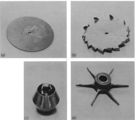
a. Disk. The plain disk can be operated at high peripheral speeds with relatively low power requirement, but it has a poor circulating capacity and can be expected t o perform well only at very low viscosities.
b. Modified disk. The sawtooth design on the rim of a disk is shown in the upper right-hand corner of Fig. 3. Contrary to popular opinion, the modi- fication does not enhance the hydraulic shear characteristic but simply magni- fies the circulating capacity of the disk.
c. Modified cone. A frustrum of a cone, open at both ends and supported concentrically on a shaft, has been widely used for dispersion. Discharge is radial through side slots. A typical commercial model is shown in Fig. 3.
d. Modified turbine. Tapering the blades of a standard flat-blade turbine produces the design shown at lower right in Fig. 3. This modification lowers circulating capacity to the desired level—which economizes on power—but retains the required peripheral shear characteristic.
E. RECIPROCATING IMPELLERS
Impellers in this class are seldom encountered. In the United States they have found utility in small autoclaves where a solenoid-type integral drive can be adopted to eliminate a shaft seal. Snyder et al. (S4) discuss this appli- cation. T h e Vibro-mixer manufactured by Chemie Apparatsbau, Mannedorf, Switzerland features a perforated plate on a reciprocating shaft which is purported to be capable of producing both intensive mixing and good circu- lation by operation at a high frequency. A reciprocating impeller of a sort is described by Mohle ( M l 2)—the impeller is a large vertical leaf pivoted at the t o p and oscillation is obtained by rocking the vessel.
Information on performance and power characteristics of this class of im- peller is t o o scant t o justify treatment in the other sections of this chapter.
FIG. 3. High shear impellers : (Λ) disk; (b) modified disk ; (c) modified cone; (d) modified turbine.
III. Power Theory
In the beginning, the impracticability of a direct mathematical attack on agitator power correlation led to employment of an empirical approach.
The subject however has much in c o m m o n with the well-substantiated meth- ods of analysis in fluid dynamics and, with the aid of dimensional analysis and the theory of models, a framework has been developed which satisfactor- ily encompasses most of the variables. M a n y of the difficulties experienced in correlating power appear to result from lack of understanding or apprecia- tion of the basic concepts.
Power theory has been discussed in detail in several papers ( R 5 , R7) b u t must be reviewed here as preamble to a critical analysis of its capabilities and limitations.
A . HISTORICAL
In the late nineteenth century we find the first evidence of work on the power characteristics of rotating impellers. T h o m s o n ( T l ) was apparently the first
to study the friction of rotating disks. Unwin (U4) extended work on disks and summarized the effect on frictional resistance of changes in speed, diameter, surface roughness, fluid viscosity, and ratio of disk diameter to tank. These early papers are commendable for their insight and experimental ingenuity.
White and co-workers ( W l , W2, W3) were the first to point out the possi- bility and advantage of correlating impeller power by dimensional analysis.
T o them goes credit for originating the drag coefficient grouping of terms now known as the power number (NP). Hixson and colleagues, in their classical series of papers on agitation, substantiated and elaborated on the theory in several reports (H4, H 5 , H6, H7). There are several pertinent comments which should be made about these pioneering studies. Their experimental facilities were somewhat crude by present-day standards, and the power data are not reliable. Also, the existence of a transition flow range and the effect of swirl on the correlation were not fully appreciated. The tendency then, in attempting to write a "power equation," was to select average exponents for the various variables—which really reflected operation under several flow conditions.
However, these works did consider many shape factors including impeller blade width and liquid depth. Unhappily, some works in recent years have tended to ignore effects of geometry, permitting the widespread but mistaken opinion that power number, Reynolds number curves established for "stand- a r d " conditions are universally applicable in all geometries.
B. DIMENSIONAL ANALYSIS
L General Equation
The general dimensionless equation for agitator power was derived by the early investigators using dimensional analysis. They considered that impeller power should be a function of the geometry of the impeller and the tank, the properties of the fluid (viscosity and density), the rotational speed of the im- peller, and gravitational force. The Buckingham pi theorem gives the follow- ing general dimensionless equation for the relationship of the variables:
D = impeller diameter, Τ = tank diameter, Ζ = liquid depth,
C = clearance of impeller off vessel bottom, w = blade width,
ρ = pitch of blades, η = number of blades,
0 (1)
where
3. Impeller Characteristics and Power / = blade length,
Ρ = density, μ = viscosity, Ρ = power,
Ν = impeller rotational speed, g = gravitational acceleration, gc = Newton's law conversion factor.
The background and development of the equation has been well presented by Hixson and Luedeke (H5), Johnstone and Thring (J2), and Rushton et al.
(R5) a n d will not be repeated in detail here.
2. Similarity
Equality of all groups in Eq. (1) assures similarity between systems of differ- ent size. The types of similarity of interest here are geometric, kinematic, and dynamic.
a. Geometric similarity. The last seven terms in Eq. (1) represent the con- dition of geometric similarity which requires that all corresponding dimen- sions in systems of different size bear the same ratio to each other.The refer- ence dimension used is the impeller diameter. The last term in Eq. (1) is not a linear dimension relationship but is required to account for change in number of impeller blades—the handling assumes use of reference to some standard condition.
Equation (1) assumes a single impeller centered on the axis of a vertical cylindrical flat b o t t o m tank. T o be fully inclusive, the equation would have to be expanded to include:
a. off-center impeller positions, b . multiple impellers,
c. baffle width and number of baffles, d. t a n k shape.
b. Dynamic and kinematic similarity. Given geometric similarity, two sys- tems are dynamically similar when the ratios of all corresponding forces are equal. Kinematic similarity requires that velocities at corresponding points be in the same ratio. These two similarity criteria are presented together since they are interrelated in a fluid system.
Confining the discussion to geometrically similar systems, Eq. (1) may be stated as
Equality of the groups in this expression insures dynamic and kinematic similarity. This relationship was derived by dimensional analysis, but the same dimensionless groups may also be obtained from the Navier-Stokes (2)
1 2 2 Robert L. Bates, Philip L. Fondy, and John G. Fenic
equation of motion. A complete discussion of the derivation and application of the Navier-Stokes equation is given in standard references such as Bird et al ( B 8 ) and Schlicting (S2) and will not be presented here. F o r the complex, three-dimensional flow in a mixing system an analytical solution to the Navier- Stokes equations cannot be obtained. However, the equations may be stated in dimensionless form as follows:
\ μ Lg pV2J where ν = velocity,
L = a characteristic length, Δρ = pressure difference.
The groups in this equation are the same as those of Eq. (2), as will be demon- strated below, and a definite physical significance may be attributed to each group.
3. Physical Significance of Dimensionless Groups
a. Reynolds number, NRe. The first group in Eq. (3), pvL/μ, is the Rey- nolds number and represents the ratio of inertial forces to viscous forces.
Since this ratio determines whether the flow is laminar or turbulent, Reynolds number is a critical group in correlating power.
In similar systems, any convenient velocity and length may be used in the Reynolds number. F o r agitation, the following are the ones generally employed:
L = D
(4) ν = ND
Substitution gives
(p)(ND)(D) D*Np
N*< = μ = — (5>
which is identical to the group derived by dimensional analysis.
b. Froude number, NFr. The group v2jLg is known as the Froude number and represents the ratio of inertial to gravitational forces. Substituting Eq.
(4) into this group gives for an agitator:
(ND)2 DN2
Ν¥τ = ~ r ^ - = (6)
r Dg g w
This is identical to the F r o u d e group obtained from dimensional analysis. In many fluid flow problems, gravitational effects are unimportant and the F r o u d e number is not a significant variable. The reason it is included here is
that most agitation operations are carried out with a free liquid surface in the tank. The shape of the surface and, therefore, the flow pattern in the vessel, are affected by the gravitational field. This is particularly noticeable in un- baffled tanks where vortexing occurs; the shape of the vortex represents a balancing of gravitational and inertial forces.
c. Power number, NP. The term, Δρ/ρν2, is the "pressure coefficient" in Eq. (3), and represents the ratio of pressure differences producing flow to inertial forces. F o r mixers, ND is again used as a reference velocity; Δρ is related to power consumption since the pressure distribution over the surface of the impeller blades could, in theory, be integrated to give torque acting on the impeller. Power could then be calculated directly from the total torque and the r.p.m. of the impeller.
In practice, the pressure distribution is not known, but in dynamically simi- lar systems it can be shown that Δρ and power are related by
Making this substitution into the pressure coefficient together with the refer- ence velocity ν = ND gives
Δρ _ kP/ND* _ kP
~pv2 " P(NDf ~ PN*D* (8'
Power is usually expressed in ft.-lb.f/min. units and density in l b .m/ f t A T o make the power number dimensionless, p o u n d force is reduced to units of ( l b .m · ft.)/sec.2 by multiplying Ρ by gc. T h e u n k n o w n constant k serves no purpose and is omitted so that the pressure coefficient for agitators (power number) is expressed as
The power number derived from dimensional analysis is the same.
A n understanding of the physical significance of the power number is en- hanced by considering it as a drag coefficient or friction factor. The drag co- efficient of a solid body immersed in a flowing stream is usually defined as
C
* = MA
(10)where CD = drag coefficient, FD = drag force on the body,
ν = velocity of flowing stream, A = cross-sectional area of the body.
For a mixing impeller, NP can be shown to be analogous to CD from the following arguments:
v OC ND
A OC D2 (geometrically similar impellers) Ρ OC NFDD
Introduction of these relationships into Eq. (10) gives
D p(ND)2D2 U U
Simplifying,
PNZD5 or
CD OC NP ( 1 2 )
The analogy of CD to TVp is a useful observation since correlations of drag coefficients and power number bear many relationships to each other; some of these will be noted below. F o r pressure d r o p in pipes, the use of friction factor is analogous to NP for impellers and CD for immersed bodies.
C . U S E OF EQUATIONS DEVELOPED FOR CORRELATION OF D A T A
7. Power Equation in Correlation Form
Equation ( 1 ) may be written in the following form:
* , -
W(Γ)· (D' ( f ) ' ( * ) ' ( = ) ' ( I ) " cn,
F o r geometric similarity, this reduces t o1
NP = ^ ( i VR e)a ( 7 VF R)B ( 1 4 ) In presenting data graphically, the usual technique in fluid flow is to use the
Reynolds number as abscissa in a logarithmic plot. To facilitate this, Eq. ( 1 4 ) can be rewritten as
Φ = ( j J ^ B = * i M u )a (15)
For a fully baffled tank, the exponent b on the Froude number generally equals
1 The use of the constants A'and Kx in Eqs. (13) and (14) is'not rigorous since Α'and Kx do not have single values for all values of the dimensionless groups. However, over specific ranges of operation (i.e., laminar or turbulent), a single value can be assigned to AT or Kx and data can be correlated by the use of the equations.
0 and φ = NP. There is disagreement a m o n g investigators on the effect of NFr in unbaffled t a n k s ; this will be discussed below.
2. General Characteristics of Correlation Curves
Typical curves of φ vs. NRe are shown in Fig. 4 for configurations often
used in practice. F o r fully baffled conditions, and in the laminar range, φ can be assumed to be NP.
a. Turbulent regime. A t high Reynolds numbers in fully baffled tanks
NP = K! (16)
This is illustrated by curves DE and / / in Fig. 4. Substituting Eq. (9) and solving for P:
P = —p NZD5 (17)
Thus in the turbulent range with geometric similarity, power can be stated to be proportional to density, to impeller speed cubed, to diameter t o the fifth power, and independent of viscosity.
D r a g coefficients of bodies in flowing streams also become constant at high Reynolds numbers.
b. Laminar regime. Lines A-B and H-B in Fig. 4 represent the viscous range of flow and the slope shown is typical for all types of impellers. Evi- dence for a slope of —1 is plentiful and, since F r o u d e effects are u n i m p o r t a n t in this range,
NP = K"(NReyi (18)
126 Robert L. Bates, Philip L. Fondy, and John G. Fenic Substituting Eq. (9),
ρ = — μΝ2Ώ3 (19)
Se
Purity of this case demands that inertial effects be negligible compared to viscous effects. The best demonstration and validation of the slope of — 1 in Eq. (18) is presented by M a c k and Uhl (M3), in which stirrers constructed of piano wire were used to almost completely eliminate inertial effects.
The drag coefficient of a sphere in viscous motion can be derived analyti- cally from the Navier-Stokes equations by neglecting all inertial terms in the equations. This is Stokes' law, and is discussed in detail by Schlicting (S2).
The drag coefficient for a sphere, like the power number, is found t o be in- versely proportional to Reynolds number which again illustrates the analogy of this case to mixing impellers.
c. Transition range. Early researchers generally assumed that a critical value of Reynolds number must exist for mixing impellers analogous to pipe flow. That a gradual change from laminar to fully developed turbulent flow does exist—and in variable form for different system geometries—is now well known, but little interest has been evidenced in why. N a g a t a et al. (N4), in the last paper of an excellent series of studies on power, considered this area briefly in connection with an unbaffled vessel. They concluded that the flow pattern is a composite of a cylindrical rotating zone in the impeller and a free vortex zone outside the blades and that the shift in balance of these due to a change in viscosity is gradual as in F to Β in Fig. 4. This does not explain why the curve for the transition range should be of such different shape and extent for various impellers, particularly in baffled systems, but the concept of the zone of flow in the impeller influenced by a secondary zone outside seems to hold promise for better understanding.
In Fig. 4, it should be noted that the shift from turbulent to transition range for the radial flow turbine ( D - B ) is not necessarily at the same Reynolds num- ber as for the axial flow turbine. This "critical" Reynolds number is not only different for the two styles of flow but can also fluctuate with either class of impeller by changes in system geometry. The value of NRe = 104 (point D) and NRe = 10 (point B), so often referred to in the literature, should be accepted only as approximate limits for the transition range.
3. Analysis of the Correlation Method
The preceding theory and equations can be accepted as fundamentally sound and, while some gaps remain to be filled, the basic concepts should provide a framework within which all power data can be fitted. However, the following comments and precautionary notes are included to avoid misuse of the correlation approach.
a. Similarity. The widespread use of a plot of NP vs. NRe to correlate im- peller power has led many to believe that all that is required for a specifica-
3. Impeller Characteristics and Power
tion of similarity of mixing- systems is equal Reynolds number regardless of geometric configuration. Dynamic similarity is obtained only when NFr and NRe are the same and geometric similarity exists. In many cases NFt and some geometric parameters are unimportant, but neglect of these factors can only lead to erroneous conclusions.
b. Froude number. In the development of the general equation (1), it was theoretically correct and logical t o consider gravitational effects. These effects are generally considered to be u n i m p o r t a n t for baffled tanks and for laminar mixing but would be expected to be a factor in unbaffled tanks where swirl exists. However, N a g a t a and Y o k o y a m a (N2) obtained good correla- lations without NFr9 using only NP as the ordinate. They state that the correc- tion for F r o u d e n u m b e r is so negligible as to be indeterminable except with an extremely accurate dynamometer. They conclude that the observed values of Rushton et al. ( R 5 , R6) in which NFt was used in correlation include errors caused by static friction in equipment.
This leads to another aspect of the subject. The frequent statement by re- viewers to the effect that " t h e data by . . . are for swirling conditions a n d therefore not useful for industrial application" has created the feeling that unbaffled tanks are to be avoided in all cases. It is then with some surprise that investigators in the area of mass transfer, such as Johnson and H u a n g ( J l ) and Laity and Treybal (LI), have noted better performance in unbaffled systems. Less disdain for swirl would seem to be in order.
c. Geometry. In correlating variations in geometry, many investigators have included geometry effects as simple factors directly in the power n u m b e r expression. This can be done as a matter of convenience, but there is n o theoretical reason for doing so, and the practice has many possibilities for error. This may be seen by considering the general equation (13). The expo- nents in the equation are not constrained to be constants by dimensional analysis, and in the general case any given exponent can depend on all of the dimensionless variables. Therefore, including one of the variables directly in the power number without a variable exponent requires that its effect be the same on power regardless of the values of all other variables. The possi- bility of this occurring would appear remote.
A n example of the improper modification of the power number is the use of the blade width w in place of a D in NP to give
N
" =
( 2 0)This implies that power varies directly with blade width, which is approx- imately true in the turbulent case but is certainly not so in the laminar and transition range. In the laminar range, it would be well to remember that Ρ oc 7V2Z)3-a wa; a is found experimentally to be about 0-5. In the transition range, as might be expected, a variable relationship exists.
There are many ways of treating the shape factors in correlating power.
The full general equation could be used but is cumbersome. Frequently, enough geometric similarity exists to cause several terms to d r o p out, and the remainder are noted as " c o n d i t i o n s " of a curve on a standard NP-NRe plot.
This procedure seems acceptable provided that the possible interaction of the remaining variables is recognized. The interaction of w/D with Reynolds number, for example, could be handled by varying w/D experimentally at very low and very high Reynolds numbers, i.e., in the fully laminar and fully turbulent regimes. In these regimes the general flow pattern is reasonably independent of Reynolds number, and the effect determined would be expec- ted to be constant within the regime.
Interactions can also occur between different geometric variables. The interrelationship between the effect of DjT and baffling in the turbulent regime as reported by Bates et al (B6) is an example and will be discussed in a later section.
IV. Power Correlations
With certain limitations, we are now able to make a reliable estimate of the power required to turn an impeller of a standard design at any speed in any environment. There is not the space available here to encompass a presenta- tion of all power data collected on all types of impellers, nor is it probably the most useful method of handling the subject. Martin (M5), Brown and associ- ates (BIO), and H o o k e r (H8) have graphed data of many investigators on various impellers, but the lack of uniformity in test conditions and in impeller design requires more interpretation and judgment on the part of the reader than is desirable. The collection of power data by Valentine and McLean in the Chemical Engineers Handbook (VI) is too heterogeneous and unqualified to be useful.
Here we will use a basic representation for the essentially standard impeller styles and geometries, as free from environmental effect (other than standard fluid property) as possible. Then the design factors to account for dissimilarity from "standard conditions" will be covered. The effect of variations in impel- ler and system geometry will be included in discussion of the basic correla- tions, but the external factors of flow pattern and special fluid properties will be treated later.
A . PROPELLERS
Considering the popularity of this impeller it comes as a surprise to find that only one study specifically on propeller power occurs before 1950. The paper of Stoops and Lovell (S6) is consequently often cited. However, this work has several deficiencies which prevent it from being of more than his- torical interest: the propeller pitch and area design used are not stated; the
φ at Reynolds No. of
Curve Source pId DjT 5 300 105
Ie (R5) 1.02 0.33 8.3 0.60 0.22
2« (R5) 1.0 0.31 8.3 0.60 0.25
3 (B5) 1.0 0.40 9.7 0.75 0.30
4 (B5) 1.0 0.33 9.7 0.82 0.35
5 (B5) 1.4 0.33 9.7 1.04 0.54
6a (R5) 2.0 0.31 8.7 1.00 0.52
1 (R5) 1.8 0.30 9.7 1.27 0.86
8 (R5) 2.0 0.31 8.7 1.10 1.0
a N o baffles.
2 . Impeller Geometry
a. Propeller pitch. This has its maximum effect on power at high Reynolds numbers as reference to Fig. 5 will show. Rushton et al. (R5, R6) report an exponent of 1.7 for / i n Eq. (13) for baffled operation; comparison of curves 4, 5, a n d 7 shows the power to vary as (p/D)1'5. The disparity is possibly in the design factor of area ratio which has been a variable.
dynamometer used for measuring power was of a type that introduces a dynamic no-load friction error; the tank was apparently unbafHed; operation was over an impeller Reynolds number range from 93 to 652. T h e exponents which they assigned to the various functions in their power equation reflect the fact that their data were taken in the transition range.
1. Power Data
Figure 5 is a correlation for modified marine propellers of the three-blade style. The data are for a single impeller and are taken from Rushton et al. (R5) and Bates (B5). Blade shape and area ratio for the propellers from these two sources differ and thus there is an expected difference in power level. Where baffling is indicated, it can be assumed that the angle m o u n t used to eliminate swirl is an equivalent design.
F o r convenience in evaluation, the power function, φ, is shown in Table I for three representative values of impeller Reynolds number. (Note that φ = NP for the baffled case and also in the laminar regime.) F o r these im- pellers, fully developed baffled turbulence is considered achieved at NRc = 105. While the unbaffled power function continues to decrease past this point, it is a reasonable limit for useful operation.
Table I
Values of φ for Three-Blade Propellers (Data from Fig. 5)
130 Robert L. Bates, Philip L. Fondy, and John G. Fenic
:::zz~zz — ::z:zzz:=:zz z ::::iz=:z z zzzz~—~: — :::iSkz:zz z oo i
/sVc
111111 1 1 1111 I 1 I 1 1 —11111111 I 1111 1 1 1 1 1 1111 I I I I 1 zd ooi
As the Reynolds number decreases, the effect of pitch becomes less notice- able. The data of Rushton (R6) show a dislocation of the curves in the laminar range but the more recent data of curves 4, 5, and 7 show no pitch effect below 7VRe = 7.
b. Blade area. This is a variable which is not yet correlated and investigation of it, in conjunction with a change in pitch, is needed. It is suggested that specification be by ratio of developed or projected blade area to disk area.
3. System Geometry
a. Impeller position. F o r all curves of Fig. 5 ; this was one impeller diameter or greater off the tank bottom. F o r baffled tanks, any location between CjD = 1 and the submergence required to prevent a vortex is presently considered sufficient to realize full power consumption. Position in an unbaffled system will have a more marked effect on power. In a given design, power investment can be increased until the vortex reaches the impeller, then power decreases due to aeration. M o r e data are needed to evaluate the exponents in Eq. (13) in both baffled and unbaffled vessels.
b. Effect of DjT. This is appreciable only at high Reynolds numbers.
Reference to curves 3 and 4 show a significant decrease in power with an increase in D/T, but data are not sufficiently extensive to accurately evaluate c in E q . ( 1 3 ) .
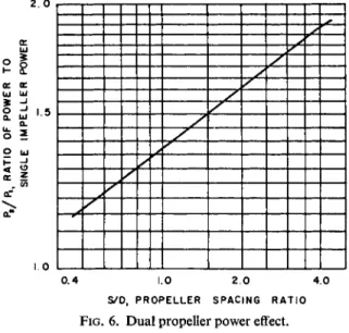
c. Multiple impellers. In low viscosity fluids, nearly five diameters of space between two propellers is required to obtain power equal to twice a single propeller. The effect of spacing is appreciable, as will be noted in Fig. 6 from Bates (B5). This curve is for high Reynolds numbers and the effect would be
2. ο
UJ
ui ui
Q. UI
ο ui
ζ :
-Λ
1.0
0.4 1.0 2.0 4.0
S/D, PROPELLER SPACING RATIO
FIG. 6. Dual propeller power effect.
132 Robert L. Bates, Philip L. Fondy, and John G. Fenic
expected to become less noticeable as operation moves towards the laminar range, the SID effect becoming minimal or nil in the laminar range.
B. TURBINES
The turbine impeller in a baffled vessel has steadily gained in importance and frequency of use and since about 1940 it has been the tool of the majority of researchers in studies of almost all applications of agitators. In most cases though, the reports have failed to fully describe the geometry of the impeller and the vessel to allow comparison of absolute power consumption. Fortu- nately, there have been a number of papers devoted explicitly to power of turbines in which the authors were fully cognizant of the effect of all variables.
References (B6, H4, M10, O l , 0 4 , R6) are complete studies, representing several different types of impellers.
1. Power Data
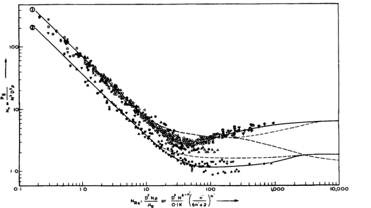
Figure 7 from reference (B6) is a correlation for the several types of turbines which have characteristically different curve forms in the transition and turbu- lent range. All impellers are seen to have reached a constant value of NP at slightly above NRe = 104. In the laminar range a nominal slope of —1 is typical for all types. The flat-blade turbine, curves 2 and 4, shows a dip below the fully turbulent value, but the transition range extends only from NRt = 15 to 1500. The d i s k a n d curved-blade styles, curves 1, 3, and 5, extend the transition range tç about 104 and also show a similar dip below the fully turbulent range. Curve 6, for pitched-blade turbines, has a shape like that of propellers in Fig. 5, as would be expected since they are both axial flow types.
For the disk style as represented by curve 1, Rushton et al. (R6) report NP = 6.3 in the turbulent range; this value is now generally considered to be high—possibly because of frictional error, as discussed by Nagata and Yokoyama (N2). Calderbank (CI) reports NP of 5.5 instead of 6.3; other of his data (C2) show a range from 4.8 to 5.5. The more recent data of curve 1 indicate the best value to use is about 5.0.
Noteworthy is that a difference in power requirement exists between the disk style of construction and the flat-blade turbine in the turbulent range.
Curve 2 is the open flat-blade style with a full blade originating at the hub.
Though it has a longer blade than the disk style, it consumes approximately 25 % less power. With reduced w/D ratios, curves 3 and 4, the difference is approximately 15%.
In Table II the power function at three representative Reynolds numbers is shown for the curves of Fig. 7. Values for several other turbine styles are also included but since the data cannot be resolved to a condition of identical geometry in every case, the information is being offered as the best available.
.01 01 01 ,01 01 I
: 11 ι 111 M I I 1 1 111111 1 I I 1111 1 I 1 I 1 1 0
8/1* α/Μ 8/1 Ό/Μ 8/lfO/M 8/1 f0/* S/lfO/M Ç/lfO/M ^S^v ^
"*" 9 3ΑΜΠ0 S 3Λβηθ » 3ΛΗΓΟ £ 3ΛΜΠ0 Ζ 3ΛΗΓΟ I 3ΛΗΠ0
I 'M ί i Ι ι u n 1 1 Η - I 1 Τ^ΤΓ " 111 1 Mil l
=11
i i Ι — Ι in 1 1 ' ι ι— ι 11111 1 ι ι— ι 111 1 Μ ι ι— ι u n 1 1 ι ι— ι I I ι Μ ι ι ι— ι 1 oo s
134 Robert L. Bates, Philip L. Fondy, and John G. Fenic
Table II
Values of φ for Turbine Agitators
φ at Reynolds No. of Db D C Baffles
Type Source w η Τ D (No.) r/w* 5 300 105
Flat Blade (4)α (B6) 8.0 6 0.33 1 (4) 12 10.0 2.1 2.6 Flat Blade (2)α (B6) 5.0 6 0.33 1 (4) 12 14.0 3.4 4.0 Disk, D/l = 4 (l)a (B6) 5.0 6 0.33 1 (4) 10 14.0 3.4 5.0 Disk, D/l = 2 (3)a (B6) 8.0 6 0.33 1 (4) 12 10.0 2.0 3.0 Curved Blade (5)a (B6) 8.0 6 0.33 1 (4) 12 10.0 1.9 2.6 Curved Blade Disk (R6) 5.0 6 0.22-0.31 1 (4) 10 14.0 3.4 4.8 Pitched Blade, 45° (6)α (B6) 8.0 6 0.33 1 (4) 12 10.0 1.5 1.3 Arrowhead (R6) 5.0 6 0.31-0.47 1 (4) 10 14.2 3.4 3.9 Arrowhead (04) — 6 0.44 — (4) 8.7 — — 2.4 Flat Blade (Ml) 4.1 2 0.23-0.37 0.35-2.5 (4) 8 & 1 0 — — 1.83 Flat Blade (M2) 3.6 2 0.31-0.52 0.55 (4) 11 — — 2.32 Flat Blade (Ol) 5.0 2 0.36-0.63 0.5-1.2 (3) 21 9.7 — 1.94 Flat Blade (Ol) 5.0 6 0.36-0.63 0.5-1.2 (3) 21 17.4 — 4.1 Flat Blade (Ol) 8.0 6 0.36-0.63 0.5-1.2 (3) 21 14.5 -- 2.5 Flat Blade (N3) 1.5 2 0.3 — (4) 15 18 7.0 8.8
Flat Blade (N3) 1.5 2 0.5 — (4) 15 10 4.2 6.0
β Refers to curves on Fig. 7.
* For pitched turbines, based on horizontally projected w.
2. Impeller geometry
a. Blade width, length, and number. Most investigators have assumed that these parameters are independent variables and have evaluated them separ- ately.
F o r flat-blade turbines, Rushton et al. (R6) obtained the following for disk turbines : the blade length effect was obtained by studying data from a number of impellers, all with a constant value of 1.25 for the ratio l/w, and based on the observation that a change in DjT did not affect power. By this method, the exponent h in Eq. (13) was found to be 1.5. Blade width as a variable was not investigated or reported. Effect of number of blades is shown by refer- ence to six blades for nl9 and the exponent / iri (n^n^ is 0.8 for less than six blades and 0.7 for eight to twelve blades.
In the fundamental study of O'Connell a n d M a c k ( 0 1 ) flat-blade turbines were used and the blade width and number evaluated as dependent variables.
They correlated data by the relation NP = K(wjD)8 and found that both the constant Κ and the exponent g varied with change in number of blades. F o r two-blade turbines, Κ is 13.8 and g is 1.23; for four blades, Κ is 19.4 and g is 1.15; for six blades, Κ is 23.7 and g is 1.09. A rewritten form of this equa- tion which shows the relation of the variables using the four-blade turbine as an example, is
Pgc = 19APN*D3*5 wiA5 (21)
N o t e that the exponents of D and w total five, to satisfy the D5 relationship.
It must be emphasized that these relationships are known to hold true only for flat-blade impellers of the open style and cannot be safely applied to disk turbines.
The study of Bates et al. (B6) covers a wide span of wjD ratios. The ex- ponent g was found to be 1.25 for four-blade turbines and 1.0 for six-blade turbines. The impellers were of open style construction similar t o that used to derive curves 2 and 4 of Fig. 7.
b. Pitch of blades. The universal use of the 45° blade angle for pitched- blade turbines has resulted, until recently, in a complete lack of data on the effect of blade angle on power. The two frequently cited sources (H4) and (V2, V3) are for unbaffled vessels and thus not applicable here. Since turbine impellers have a constant blade angle, as contrasted with the heliocoidal de- sign of propellers, the term " p i t c h " has no real significance. Thus, the corre- lation of power with pitch should be based on a function of blade angle rather than the (p/D) term of Eq. (13).
In reference (B6) a blade angle range of 25° to 90° w^s studied with the projected blade width (w sine Θ) held constant. T h e angle Θ was measured from the horizontal. F o r four-blade open-style pitched-blade turbines it was found that the {pjD)f'm Eq. (13) can be replaced by (sine θ)2·5 in the turbulent range.
136 Robert L. Bates, Philip L. Fondy, and John G. Fenic
c. Curvature of blades. This had a negligible effect on power at high Rey- nolds numbers in the study of reference (B6) (see curve 5 of Fig. 7). The only other investigation of this effect is that by Van de Vusse (V3). H e found NP to vary with (sine </>)°"23> where φ is the angle between the blade tip and a tangent t o the periphery. However, these data were taken with a stator ring present and thus the curvature is not isolated as an impeller variable.
d. Shrouds. The shrouded impeller included in the power runs of Rushton et al (R6) was a special type similar to a centrifugal p u m p impeller, and the separate influence of the shroud is not obtainable. Lee et al. (L2) used a shrouded disk turbine in their high viscosity work and presented power data in the laminar and transition range indicating that shrouding requires as much as 5 0 % greater power. That their two sizes of turbines did not correlate was attributed by the authors to experimental error in reading temperatures and viscosities. In reference (B6) data are reported for the two most c o m m o n shroud modifications. In the turbulent range with shrouded plate fully cover- ing the t o p of the turbine the power increase was found to be 30 %. With a full b o t t o m shroud a 47 % increase was reported.
e. Tilted-blade mounting. This type of mounting of an impeller is reported (L5) to have power consumption identical to straight bore mounting, inas- much as the discharge area of the impeller periphery is unchanged.
3. System Geometry
a. Position. The proximity of a turbine to the free surface of a liquid batch would have a negligible effect on power as long as full baffling existed and the location were not so abnormally high as to permit a vortex. The clearance beneath the impeller, however, is of importance. For the two-blade turbines of Mack and Kroll ( M l ) no change in power was noted for locations over the range of C\D values of 0.35 to 2.5. The data of Miller and M a n n (M10), although taken on unbaffled vessels also indicate a minimal effect of bottom clearance for flat-blade turbines. This same work notes a reduction in power for a pitched-blade turbine below CjD = 0.75. In a more complete study (B6) the proximity to the vessel bottom was found to be significant for flat- blade, disk-type, and pitched-blade turbines. The disk-type impeller was found to exhibit a reduction in power with decrease in clearance while the opposite effect was noted with a pitched-blade turbine. The flat open-style turbine displayed a variable effect with minimum power consumption measured at CjD = 0.70. The results are shown in Fig. 8. The effect of wall baffling for two conditions is also shown. The impellers were six-blade styles with all data taken in the turbulent range.
b. DjT and baffles. The studies of Rushton et al. (R6) indicate no effect on power over a range of DjT ratios of 0.15 to 0.50. References (M2) and ( O l ) also note no influence of this parameter. The effect on power of variation in the number of vertical side-wall baffles and baffle widths has been presented
in two contemporary works, although the findings are not in agreement.
Bissell et al. (B9) tabulated, without supporting data, the per cent power based on four baffles of width Γ/12 and show an increase in power above four baffles and above Γ/12 width. Mack and Kroll ( M l ) found a limiting condi- tion of number and width of baffles, above which no increase in power occurred.
The more recent work of Nagata and associates (N3) shows that the power for a given number of baffles reaches a maximum and then decreases some- what as width increases. An approximation of their results gives the relation
ψ
= 0.5 (22)for maximum power consumption. This result, however, was based on a study involving a two-blade impeller in only one vessel diameter.
Bates et al. (B6) report that an effect of DjT ratio on power exists with an open-style six-blade flat-blade turbine and that this effect is interrelated with the extent of baffling present. Their results are shown in Fig. 9 with data points omitted for clarity. The baffle ratio on the ordinate is the form pro- posed by Nagata, although maximum power consumption occurs at some- what less than a baffle ratio of 0.5. It was found that at low baffle ratios the power decreases with increasing D/T while the converse was found at high baffle ratios. All data were taken in the turbulent range.
c. Multiple impellers. The way power is affected by spacing is shown in
138 Robert L. Bates, Philip L. Fondy, and John G. Fenic
NP
Q08 0.2 0.3 0.4 0.5 0.6
BAFFLE RATIO ^
FIG. 9. Effect of baffling and DjT on power.
α β 1.0
Fig. 10 from (B6). Spacing, S, as used here is the vertical dimension between the b o t t o m edges of the two turbines and thus a spacing of 0 indicates com- plete coincidence of the two impellers. In the ratio
Ρ
2/Λ>
the reference power Px is a flat-blade turbine in all cases. The pitched blade then falls lowest and the combination of the two styles is intermediate. Within a spacing of four impeller diameters, it is seen that dual pitched-blade turbines do not yet\
ο Z5
2.0
1.5
1.0
Q5
OUAL FLAT r OUAL FLAT
•
F L AT a P I T C H ED
i
Y
DUAL P I T C H ED
0.5 L0 1.5 2.0 Z5 3.0 3.5 IMPELLER SPACING RATIO - S/D
FIG. 10. Effect of dual turbine spacing on power.
C. PADDLES
After the work of White and Somerford and their contemporaries there was a span of about fifteen years in which the paddle was de-emphasized in power studies. The papers of Hirsekorn and Miller (H3), Magnusson (M4), and O'Connell and M a c k ( O l ) were the first to scrutinize the laminar range specifically for paddles. The recent comprehensive studies by N a g a t a and associates ( N l , N 2 , N 3 , N4) have greatly improved our theoretical and quantitative knowledge of paddles, particularly in unbaffled systems at high Reynolds numbers. But still, most data are only on the basic paddle or minor modifications of it. Only scattered power data on the more complicated styles are available and that from sources where the main interest was in functional performance; e.g., the heat transfer studies with anchors by Uhl (U2) and Uhl and Voznick (U3).
F o r convenience, paddle power data will be presented in a different manner from that used for propellers and turbines. The typical NP-NRe plot is applic- able, of course, but in the laminar range a few equations will suffice for the basic paddle. In the turbulent baffled range the data cannot be compressed in- to a reasonable space and retain usefulness. The various modifications of the basic paddle require too much qualification to allow tabulation of design and power characteristics so they will be discussed in as much depth as possible.
1. Laminar, Basic Paddle
a. General equation. F o r a basic multiblade paddle, correlating width and diameter, the general equation is
Pg.
PN3D or
= κΆ'
(24)equal twice the power consumption of a single turbine. The combination of two types, the pitched above the flat, reaches a level of the sum of the two at about one diameter spacing. But it will be noted that two flat-blade turbines actually develop a total power almost 25 % greater than the sum of the two when spacing vis less than one diameter. This is attributed to an effect in which the proximity is such that the space between the blades approaches the condition of a continuous blade.
d. Direction of rotation. This is not important with a flat-blade turbine but with a pitched-blade style it may have an effect. The only data on this are by Hixson and Baum (H4). They show that power consumption is identical at a Reynolds number of 106 but below that the standard down-thrust style (which they term "reversed rotation") shows a lowering of power and a gradual divergence from the up-thrust style.
140 Robert L. Bates, Philip L. Fondy, and John G. Fenic
where g is a function of the number of blades. F o r the two-blade form the experimental data of O'Connell and Mack ( 0 1 ) yield the power equation
/> = — μΝ2Ό2Λ* w™2 (25)
Se
This is checked remarkably well by Hirsekorn and Miller (H3) who found Ρ oc D25 w0 , 5. Their value of K is in agreement with O'Connell and M a c k at NRe = 1 but decreases to a constant value of 95 in the range from NRt = 0.2 t o 0.004.
b. System geometry. Although the data of reference ( 0 1 ) were taken over a range of system variables, no indication is given of any effect. In reference (H3) the DjT function was studied in the range of 0.25 and 0.51 and a negli- gible effect demonstrated.
c. Multiple impellers. In the viscous range both Lee, et al. (L2) and Metzner et al. (M8) report that two impellers will draw twice the power of a single paddle, provided spacing is greater than one diameter and DjT is less than 0.8. On the other hand, Nagata et al. (N3) state that the spacing of paddles has negligible effect on power and they are able to equate two paddles with no space between them to a single paddle of double blade width.
2 . Unbaffled, Basic Paddle
Above a Reynolds number ranging from 10 to 100 the position and shape of the curve in the NP-NRe plot is a function of both impeller and system variables and it is not feasible to present a single curve and supplement it with correction factors. The publications of Nagata and co-workers ( N l , N 3 , N4) are very detailed in treatment of all variables and it is recommended that these references, particularly the last two, be consulted. (The Memoirs of the Faculty of Engineering, Kyoto University are printed in English.)
3. Paddle Modifications
a. Pitch. Van de Vusse (V2, V4) made a few tests with a three-blade pitched paddle, unbaffled, which correlated with some of the four-blade data of Hixson and Baum (H4) to give NF oc (sine 0 )2 , 5. The range of Reynolds number over which this was found valid is 9560 to 28,950. Hixson and Baum (H4) found pitch t o affect power only between JVRe = 200 and 104—at higher and lower Reynolds numbers, on a plot of power function vs. Reynolds number, the curves converged. Nagata et al. (N4), who ran a series of im- pellers over a blade angle range of 15° to 90° and DjT ratios from 0.15 to 0.5, did find convergence below a Reynolds number of about 5. But at TV^ = 106 the curves were still diverging and it must be assumed that the high Reynolds number data of Hixson and Baum (H4) are in error. Since the pitch effect is dependent on both DjT and DjZ, in addition to Reynolds number, Nagata