The effects causing the burning of plastic coatings of fire-resistant cables and its consequences
Zsuzsanna Kerekes1•A´goston Resta´s2•E´va Lublo´y3
Received: 17 December 2018 / Accepted: 25 June 2019 / Published online: 6 July 2019 The Author(s) 2019
Abstract
Electric wiring is part of the fire protection systems; therefore, it must work reliably for a given period of time. Cable is in the first place among the cause of fire. Fires are always triggered by unsafe and nonstandard conditions, so we can approach safety if we know the properties of cables we want to use. We recommend adding standard ratings (PH, EP) with overload and combustion in increased/higher oxygen ratio. A plastic-coated cable does not burn in normal air, but, in a higher oxygen ratio, it shows specific burning phenomena. Cable fires may have two starting points: One is the heat reaching the plastic insulation of cables, due to the fire created by burning; the other one may be due to the fire generated by the overvoltage in the inappropriately sized cables when the outer plastic coating begins to burn. The basic condition of fire retardancy is that wire breaks or short circuits may not occur in a cable system. During this research, both effects are tested on fire-retardant cables. On the one hand, we exposed wires of various plastic sheaths to flame and to heat, as well as tested at which actual oxygen content they start combustion and flame propagation. In addition, we have investigated how fire- resistant cables react to a possible overvoltage when auto-ignition occurs. The goal was to see how conventional tests reflect requirements caused by a real fire and what the actual fire resistance of cables is, as well as examining whether the cables that have been certified as fire-resistant meet the requirements under real fire. The limited oxygen index (LOI) parameter seemed to be the most appropriate for real fire resistance. Our results have shown that factory certifications are not enough to provide complete fire safety. For example, the PH 180, E90 best rated plastic gave the weakest LOI value.
PH 30 and PH 120 has proved correct the flammability. Due to the complex layers their investigation their testing is complex to, requiring a variety of tests to give a complete burn behavior. The most important exothermic peaks of diagraphs give the expected LOI values. The first and second decomposition is only indicative of damage and smoke, that is only by the tests with overload to see.
Keywords Fire-resistant cableElectric firesCable firesThermal decomposition and pyrolysis of plastics OverloadCable fires
& E´ va Lublo´y
lubloy.eva@epioto.bme.hu Zsuzsanna Kerekes Kerekes.Zsuzsa@ybl.szie.hu A´ goston Resta´s
Restas.Agoston@uni-nke.hu
1 Fire Protection Testing Laboratory, Institute of Fire Protection and Safety Engineering, Ybl Miklo´s Faculty of Civil Engineering, Szent Istva´n University, Budapest, Hungary
2 Department of Fire Prevention and Rescue Control, National University of Public Service, Hunga´ria krt. 9-11,
Budapest 1081, Hungary
3 Department of Construction Materials and Technologies, University of Technology and Economics, Budapest 1521, Hungary
https://doi.org/10.1007/s10973-019-08526-9(0123456789().,-volV)(0123456789().,- volV)
Introduction
Electric cables have a dual role from a fire protection aspect:
1. they are part of fire protection systems and assist in escape and rescue,
2. they may be the cause of fires, increase the propagation of fire and contribute to greater damages.
Electric current is the commonest cause of fire; world- wide, half of all the fires cause injuries, death, material damage, failures and, very often, the complete destruction of devices [1]. In Hungary as well, electric fires have also been increasing in recent years and are the second com- monest cause of fires [2].
The amount of temperature required for ignition is pri- marily defined by the kind and condition of the insulating material used in electrical conduit systems. The ignition of plastics occurs at 300–400C, which results from a com- plex sequence of events, whose last phase immediately before ignition is
• the formation of electric arc or
• the development of excess heat due to operation.
This heat can be generated from an erroneous design (e.g., conduit diameter, the size of fuse, etc.), due to poor construction, the technical failure of electrical equipment, the operation of equipment, etc.
The fire protection mechanism of plastic coatings (sheaths)
An important design goal for cables is to maintain the circuit integrity and guarantee that the working time of the cable is longer than the duration of the fire [3,4]. Generally speaking, to guarantee a sufficient working time for the safety equipment, either the cables or the systems must be designed to be resistant to fire. In standard conditions, these cables or systems can provide electrical continuity for 15, 30, 60, 90 or even 120 min. Cable design, insulation and sheathing materials together determine the efficiency of cables against flame ignition and propagation [5]. Special care must be taken when cable lines are installed in areas with increased risk of fire or increased incidence of people.
Fire-resistant cables, so-called low-fire-hazard cables (LFHCs), have been developed to satisfy the requirements of low flame propagation and heat release together with very low emission of smoke and hazardous gases [6,7] and should be used in such situations. Polyvinyl chloride (PVC) is one of the most widely used polymers in the field of electrical and control cables. When considering flamma- bility in general, PVC is essentially considered to be self-
extinguishing. However, PVC is able to support flame propagation along its length. Passive fire protection is coatings and fire-stops and the use of inherently flame- retardant materials [8]. The propagation of fire along PVC- sheathed electrical cables may be diminished by using flame-retardant smoke-suppressant (FRSS) additives and by applying fire-retardant intumescent coatings to the sur- face of the cable sheath. When the FRSS additives are used, plasticized PVC compositions incorporating a molybdenum-based organic (MBO) complex have been found to offer excellent smoke suppression, and have a fairly high limiting oxygen index (LOI)—particularly when plasticized with a phosphate plasticizer (i.e., they act as an FRSS additive). Both of the fire protection methods, the use of a fire-retardant coating directly on the cable surface or inserting the cable into a fire-retardant coated steel conduit, are able to delay the failure time of polyvinyl chloride (PVC)-insulated electrical cables. Failure time increases with the thickness of the coating. If the fire-re- tardant coating is applied directly on the cable surface, the fire-retardant coating thickness should be limited to approximately 1 mm. If the cable is inserted into a conduit with a fire-retardant coating, the appropriate range of the coating layer thickness is 1–2.5 mm. Compared with the method of applying the fire-retardant coating on the cable surface directly, inserting the cable into a fire-retardant coated conduit is more effective in protecting the cable, and the failure time is much longer. However, neither of these two methods is appropriate for protecting electrical cables that must supply power (or transmit a signal) to equipment that are required to operate for relatively long durations of fire. Therefore, usual cables, even if protected with fire-retardant coating, are unsuitable for providing electricity to safety installations that must continuously operate even under fire. The proper method for achieving acceptable fire resistance properties is to use either cables or systems specifically designed for fire resistance [9].
Fireproof functionality is made by using organic or inorganic flame retardants as cable compounds, for reducing flammability, delaying combustion or inhibiting fire spread. Large quantities (60–70%) [10,11] of inorganic filler materials such as metal hydroxides (aluminum tri- hydroxide, Al(OH)3, or magnesium hydroxide, Mg(OH)2) are widely used. Their interaction with fire has previously been described by many authors [12–17] and can be briefly summarized as follows:
• retardants slow the thermal decomposition of the overall material by releasing a significant amount of water in an endothermic reaction and so absorb the energy from the combustion zone and
• retardants produce char and a metal oxide coating that can act as a protective layer during combustion.
Together with the aforementioned retardants, the fire- proof functionality of cables can be further improved by incorporating a special fire-protective layer (fire barrier) within the cables (such as glass tape, mica glass tape or ceramifiable silicone rubber).
The polymer structure of plastics changes due to per- sistent or repeatedly high temperatures (200–300C).
Their insulating capacity, due to the semiconductor capa- bility of the carbon generated, can deteriorate to such an extent that it can lead to the formation of arcing short circuit. Plastics have a different risk of carbonizing. PVC is the most common insulating material; however, in this respect, it belongs to the worst performing plastics.
Regulation of the use of fire-resistant cables
The criterion of fire resistance classification is that there may be no cable break or short circuit in the cable system.
Therefore, DIN 4102-12 [18] distinguishes fire resistance classes according to Table1.
The purpose of the tests described in standard series (EN 50200, EN 50362 and IEC 60331 [20]), relating to retaining insulation, is to certify that if fire affects a fire- retardant cable, with a small simultaneous mechanical load, it will remain operational for some time.
The requirement of classification is for a cable to maintain its current conductivity within the test period.
Cables performing the test requirements successfully are marked with PH marking and time values shown in min- utes, for example ‘‘PH90.’’ IEC 60331, which is essentially EN 50200, but it does not apply mechanical stress and results in FE marking.
According to IEC, EN and DIN standards as well, it is generally proven for cable testing that IEC has the longest and DIN the shortest resistance time. This is justified by the fact that the effects resulting from the deformation of the holder structure significantly affect the operability of the cable and ultimately the entire cable system. We have also proved it in the case of bent cables [21].
Generally said, the ratings and the absence of the above- mentioned standards do not cover the testing of overload- ing, caused by warming and ignition. It does not provide
information on the long-term functioning of cables, i.e., aging. Our paper tries to address this issue.
Experimental materials and methods
Cable specimens for testingWe have selected the test specimen in a way that they are preferably of different types and classifications, e.g., PH30, 90, 120, 180. We have selected five cables with different fire retardancy for testing. The material of the conduits was always copper. We specify the characteristics of the cables in Table2. The unspecified external coating is usually PVC, and only specimen 3 is polyolefin.
For the oxygen index (LOI) and flame propagation test, we have cut 16-cm sections from each specimen type, ten pieces per specimen. First, we examined separately the outer sheath, and then, we scrutinized the behavior of the internal layers both one-by-one and in pairs, and in the case of combined placement of multiple cables. We cut out 50-cm pieces from each specimen to test overloading and flame propagation.
Tests
Measurement of limited oxygen index
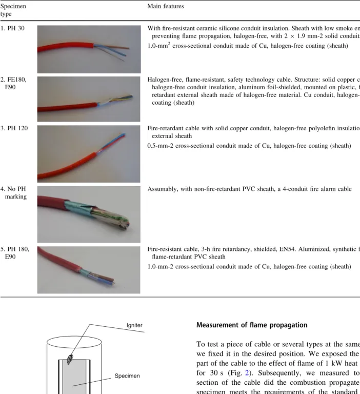
The definition of the limited oxygen index (LOI) is an important material parameter for assessing the com- bustibility of combustible substances, which can be used in principle for any combustible solid. This is the only parameter by which we may numerically characterize the flammability of plastic substances in different air condi- tions. According to this study, the flammability of materials can be characterized with the minimum oxygen concen- tration as well at which they still burn. Most of the com- bustible materials at normal oxygen content (21 vol%) are capable of burning, but there are substances that are not.
Limited oxygen index is the value when the burning reaches 8 cm on the specimen with testing apparatus of type FIRE ISO 4589 (Fig.1).
Technical data of the apparatus are given as follows:
Oxygen analyzer: range 0–100% O2, Repeatability:±0.1% O2,
Linearity:±0.1% O2,
Flow: flow-through column adjustable from 0 to 20 nl min-1.
Table 1 Fire resistance classes [19]
Fire resistance class Fire resistance duration/min
E30 C30
E60 C60
E90 C90
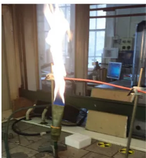
Measurement of flame propagation
To test a piece of cable or several types at the same time, we fixed it in the desired position. We exposed the lower part of the cable to the effect of flame of 1 kW heat output for 30 s (Fig.2). Subsequently, we measured to what section of the cable did the combustion propagate. (The specimen meets the requirements of the standard if the carbonized section is in the range of 50–540 mm, in ver- tical placement, measured downward from the upper clamp.)
We also tested the behavior of a cable bent due to fire.
We also exposed the specimen to mechanical effects during the test, simulating real conditions.
Table 2 Features of cable specimens Specimen
type
Main features
1. PH 30 With fire-resistant ceramic silicone conduit insulation. Sheath with low smoke emission, preventing flame propagation, halogen-free, with 291.9 mm-2 solid conduits 1.0-mm2cross-sectional conduit made of Cu, halogen-free coating (sheath)
2. FE180, E90
Halogen-free, flame-resistant, safety technology cable. Structure: solid copper conduit, halogen-free conduit insulation, aluminum foil-shielded, mounted on plastic, fire- retardant external sheath made of halogen-free material. Cu conduit, halogen-free coating (sheath)
3. PH 120 Fire-retardant cable with solid copper conduit, halogen-free polyolefin insulation and external sheath
0.5-mm-2 cross-sectional conduit made of Cu, halogen-free coating (sheath)
4. No PH marking
Assumably, with non-fire-retardant PVC sheath, a 4-conduit fire alarm cable
5. PH 180, E90
Fire-resistant cable, 3-h fire retardancy, shielded, EN54. Aluminized, synthetic foil, red flame-retardant PVC sheath
1.0-mm-2 cross-sectional conduit made of Cu, halogen-free coating (sheath)
Nitrogen Oxygen
Igniter
Specimen
Specimen holder
Glass cylinder
Fig. 1 Typical apparatus for determining limited oxygen index
Measurement of overload
When overloading the cables, we observed how they behave as a result of excess voltage and current and when the ignition occurs. During the test, we cut the specimens into 50-cm pieces. We connected the sections of the cable to a serial circuit. We cut off the insulation at both ends; at 2-by-2 cm lengths, we fixed them with a pair of clamps of a starter cable. An ammeter was also added to the circuit, directly in front of the loaded wire. To regulate the current, we used a powerful toroid capable of producing up to 150 A. The temperature of the specimen cable was mea- sured by a thermocouple type K, attached tightly to its center.
We increased the amperage step by step. When the increasing temperature dropped, we raised the amperage.
We read the temperature data every 30 s.
Derivatography (thermal analysis)
Changes in phases were followed by TG/DTG/DTA serves using MOM Derivatograph-Q 1500 D TG/DTA instrument.
During the measurements, the reference material was alu- mina (Al2O3), the mass of samples were ca. 300 mg, and the samples were heated at 10C min-1heating rate up to
*1000C, in air atmosphere (in static condition). Before the investigations, the specimens were ground in an agate mortar, and directly after that, they were measured in the TG/DTA device, avoiding samples from carbonation due to the airborne CO2. The thermoanalytical test results were evaluated by Winder (version 4.4.) software.
During the thermal analysis test, we subjected the components of each cable (coverage, foil, cellophane) to a separate derivatograph test.
Results and their assessment
Measurement of flame propagation in normal air
All the coatings tested were self-extinguishing in normal air at 21% from O2. Several types dripped when burning, and melted and smoked. Despite the fact that there was no propagation of fire, the following combustion phenomena could be observed:
• Individual testing of specimen 3 (straight): Exposed to flame for 15 min, the plastic coating burnt completely, but the rest of the interior did not. The fire did not propagate.
• Testing of specimen 3 (bent), longer self-sustaining burning: At 14th minute, we simulated a mechanical effect; only the ash layer fell off (25-min test).
• Conjoint testing of specimen 2 (straight and bent):
dripping with burning; the bent specimen cracked in the 5th second after ignition, self-sustaining burning; then the external costing burnt and extinguished itself again.
(15-min test).
• From type 1, straight and bent specimen, and type 1:
self-sustaining burning; the bent one cracked; testing the internal components of cables types 1, 2 and 3:
burning while cracking in the first 2–3 s; self-sustaining burning; the burning ceased at 10:00 min.
• Testing the foils of types 3 and 2: After 20 s, they break apart and completely burn and smoke.
It is worth mentioning the observation that the external mechanical effect greatly influences the performance of the cable, since the burnt coating (sheath) is ceramized on the cable, causing the insulation effect, but if it separates from the cable due to an external force or is damaged, the cable remains without protection.
Combustion in an increased oxygen content
As we have seen it at flame propagation, none of the specimens is able to, at 21% oxygen content of air, main- tain self-sustaining combustion; however, at different oxygen contents, we can distinguish them according to the flammability. The type with the lowest oxygen index is the closest to the oxygen in the air, i.e., it would burn the best.
In Fig.3and Table3, we show the development of the oxygen index referring to the different specimens. Based on this figure, we can draw the following conclusions. The results refer to the outermost sheath:
Fig. 2 Testing flame propagation (Fire Protection Testing Laboratory, Institute of Fire Protection and Safety Engineering, Ybl Miklo´s Faculty of Civil Engineering, Szent Istva´n University)
• Although specimens 1 and 2 have different classifica- tions, they have almost the same oxygen index.
• Specimen 5 (PH80, E90) showed the lowest LOI: 27.5, i.e., it is the least resistant to heat and fire, although it has E90 value.
• Specimen 3 (polyethylene), on the contrary to the other specimens, seems to be the most resistant to fire.
We have tested not only the external conduits of cables, but also the internal ones separately: On a small flame effect, they were self-extinguishing at the oxygen content of the air, but even at 33% oxygen, during combustion, they fully burnt with smoke and flame. For the purpose of defining the exact oxygen index, one may only burn one conduit/wire, because the heat of the adjacent flame impacts on the combustion of the cable tested, with the temperature dependence of the oxygen index, mentioned earlier.
Results of measuring overload
Due to overload of copper the increase of the temperature, also in many cases the red glow was visible. The resistance to current loads does not depend on the flammability of the outer casing/fire retardancy, shielded but on the thickness of the copper conductor. Effects of current on the damage are shown in Table4and Figs.4–7.
The time and temperature measured, referring to the first signs of failure and the actual failure, during the over- loading of certain elements, are summarized in Fig.6 and Table4. Our observations are as follows:
• Specimen 2 ignited the fastest and at the lowest temperature despite the fact that this cable has E90 fire retardancy values.
• The LOI value of the external plastic sheath of specimen 3 is the highest (the only non-PVC), but since the Cu conduit broke before the temperature of the insulation reached the zone of 300-400C, critical for plastics.
• Specimen 5: The failure of this cable with E90 fire retardancy occurred much later (at 60 A) and at a higher temperature (700C) than the previous ones. Despite the fact that the fire retardancy of the outer sheath is quite low (LOI 27.3), due to the thick conduit the circuit worked even when the outer sheath has melted (200C) and burnt down from it, starting at 300C.
• Specimen 1: despite the fact that its fire retardancy classification is different, it showed just as advanta- geous results as specimen 5.
Based on these facts, the ratings so far did not really show the discrepancies and the real behavior of the cables.
We consider it important to observe that the high fire resistance of the outer coating does not in itself reflect the
20%
22%
24%
26%
28%
30%
32%
34%
36%
38%
40%
1. specimen (PH30)
2. specimen (FE180, E90)
3. specimen (PH120)
4. specimen 5. specimen (PH180, E90)
Limited oxygen index/%
Fig. 3 Development of the oxygen content of the outer plastic sheath in the case of different specimens
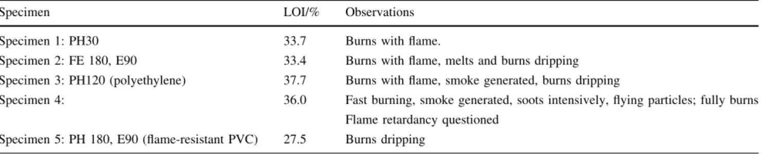
Table 3 Observations of the burning of the different specimens at different oxygen indexes
Specimen LOI/% Observations
Specimen 1: PH30 33.7 Burns with flame.
Specimen 2: FE 180, E90 33.4 Burns with flame, melts and burns dripping Specimen 3: PH120 (polyethylene) 37.7 Burns with flame, smoke generated, burns dripping
Specimen 4: 36.0 Fast burning, smoke generated, soots intensively, flying particles; fully burns Flame retardancy questioned
Specimen 5: PH 180, E90 (flame-resistant PVC) 27.5 Burns dripping
actual operational loads, because if the conduit is made of thin Cu, it would break earlier than the failure of the sheath that would take place. The copper conduit broke before the plastics would burn (in the case of specimens 2 and 3).
However, an oversized copper conduit could also be a source of fire hazard because it can still conduct current, when glowing, even without a sheath (in the case of Table 4 Main features of the overload of cables
LOI/%
(external sheath)
First signs of failure
Carbonization Ignition Conduit break
Specimen 1 PH30
33.7 152C Slightly smoking at the edge
(50 A) 308C The plastic starts
softening.
470C The cable fully carbonized and turns black (58 A)
770C Sudden ignition, burns with flame. Current flows through it
(56 A)
None
Specimen 2 FE 180, E90
33.4 189C
Smoking, insulation bubbling (38 A)
200C
Sheath carbonized (40 A)
Did not reach it 224C
The conduit broke earlier than the failure of the insulation
Specimen 3 PH 120 FR
polyethylene
37.7 188C
Smoking
Did not reach it 275C
The conduit broke earlier than the failure of the insulation.
Specimen 4 36.0 No current load, the specimen failed at its initial flame test Specimen 5
PH 180, E90 FR PVC
27.5 151C
Smoking (46 A) 255C
Brownish color on the external sheath of the insulation (oxidization)
(50 A)
700C After ignition, current still
can be measured
Specimen 1 (LOI 33.7) Specimen 2 (LOI 33.4)
Specimen 3 (LOI 37.7) Specimen 5 (LOI 27.5) Fig. 4 Visible behavior of the
different specimens during the overload tests
0 200 400 600 800 1000 1200 1400 1600 1800 1. specimen (PH30)
2. specimen (FE180, E90) 3. specimen (PH120) 5. specimen (PH180, E90)
1. specimen (PH30)
2. specimen (FE180, E90)
3. specimen (PH120)
5. specimen (PH180, E90)
Temperature (°C) 490 200 188 390
Time (sec) 1140 600 510 1530
Temperature (°C) Time (sec) Fig. 7 Time and temperature
referring to the functional failure
0 100 200 300 400 500 600 700 800 900
0 200 400 600 800 1000 1200 1400 1600 1800
Time/s
Tempereture/°C
1. specimen˙(PH30´) 2. specimen ˙(FE180, E90´) 3. Specimen (PH120) 4. specimen (PH180, E90) Fig. 5 Development of the
temperature depending on time at the overload testing
0 200 400 600 800 1000 1200 1400 1600 1800 1. specimen (PH30)
2. specimen (FE180, E90) 3. specimen (PH120) 5. specimen (PH180, E90)
1. specimen (PH30)
2. specimen (FE180, E90)
3. specimen (PH120)
5. specimen (PH180, E90)
Tepmerature (°C) 770 224 275 700
Time (sec) 1260 735 870 1612
Tepmerature (°C) Time (sec) Fig. 6 Time and temperature
referring to the first signs of failure
1st marked cable LOI: 33.7
2nd marked cable LOI: 33.4
3rd marked cable LOI: 37.7
4th marked cable LOI: 36.0
Endoterm Exoterm
0.0 0.0 200.0 400.0 600.0 800.0 1000.0
20.0 40.0 60.1 80.1 100.1
– 500.0 – 390.0 – 280.0 – 170.0
mg – 60.0 50.0
TG
MDTG
DTA
T 1
2
3
4
TG
MDTG
DTA
T
1 2
4 3
5 6
TG
MDTG
DTA
T
1 4
3
TG
MDTG
DTA
T 1
4
5 3
2
°C
0.0 0.0 200.0 400.0 600.0 800.0 1000.0
20.0 40.0 60.1 80.1 100.1
– 500.0 – 390.0 – 280.0 – 170.0 mg – 60.0 50.0
°C
0.0 0.0 200.0 400.0 600.0 800.0 1000.0
20.0 40.0 60.1 80.1 100.1
– 500.0 – 390.0 – 280.0 – 170.0 mg – 60.0 50.0
°C
0.0 0.0 200.0 400.0 600.0 800.0 1000.0
20.0 40.0
min
60.1 80.1 100.1
– 600.0 – 470.0 – 340.0 – 210.0 mg – 80.0 50.0
°C
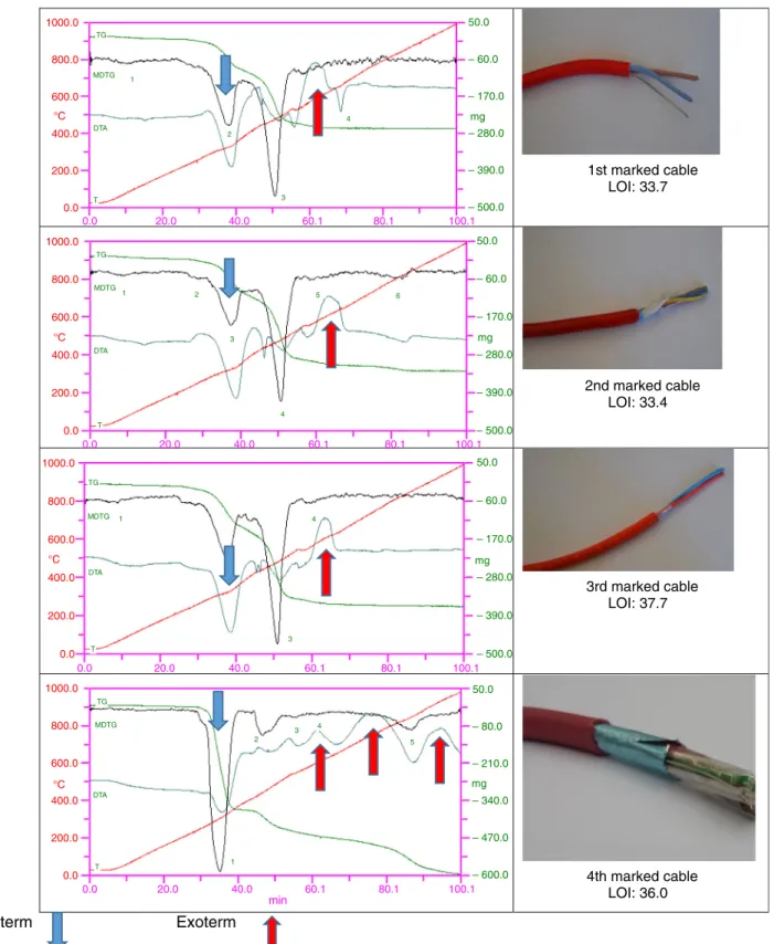
Fig. 8 Derivatograph recording of the external coverage of the cables
Table 5 Most typical thermodynamic values of the of the external coverage of the cables Main endothermic
peak
Main endothermic peak
Max. exothermic peak (pyrolysis)/C
Total loss of mass/%
LOI
Cable 1
Beginning of the degradation (Peak 2)/C
231.1 379.1
End of the degradation/C 379.1 614.1
Loss of mass of the peaks/% 17.52 33.12 53 33.7
(Peak between 3 and 4) 400–550
Cable 2
Beginning of the degradation (Peak 3)/C
276.6 396.8
Beginning of the degradation/C 396.8 530
Loss of mass of the peaks/% 18.63 34.15 63 33.4
(Peak 5) 550
Cable 3
Beginning of the degradation (Peak 2)/C
205.1 398.3
Beginning of the degradation/C 398.3 548.5
Loss of mass of the peaks/% 22.26 34.66 61 37.7
(Peak 4) 590
Cable 4
Beginning of the degradation (Peak 1)/C
242 Continuous pyrolysis
Beginning of the degradation/C 371
Loss of mass of the peaks/% 46.51 76 \36
2nd marked cable 3rd marked cable
4th marked cable
Endoterm
0.0 0.0 200.0 400.0 600.0 800.0 1000.0
19.9 39.7 59.6 79.4 99.3
– 100.0 – 78.0 – 56.0 – 34.0 mg – 12.0 10.0
– 100.0 – 78.0 – 56.0 – 34.0 mg – 12.0 10.0
– 100.0 – 78.0 – 56.0 – 34.0 mg – 12.0 10.0 TG
MDTG
DTA
T
1
TG
MDTG
DTA
T
2 1
TG
MDTG
DTA
T
2
1 3
°C
0.0 200.0 400.0 600.0 800.0 1000.0
°C
0.0 200.0 400.0 600.0 800.0 1000.0
°C
0.0 20.0 40.0 60.1 80.1 100.1
0.0 20.0 39.9 59.9 79.8 99.8
Fig. 9 Derivatograph of the blue foils
specimen 5). Unfortunately, it could be forecasted because of the low LOI value.
Results of derivatography External coverage
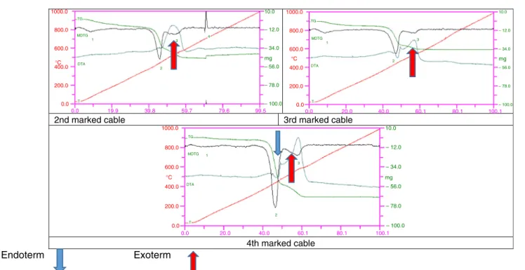
In Fig.8, we show the derivatography views of the external coverage of the cables. In the case of the specimen 4 marked non-fire-retardant PVC sheath is clearly visible the effect of the lack of the additive flame retardancy: At about 240C, the thermal decomposition begins, and it means the half of the total mass of the material. The released decay products continuously provide the exothermic peaks 2, 3, 4 and 5. Table5 shows the most typical thermody- namic values of the external coverage of the cables, which are the basis of combustion.
The significant mass loss of the samples (1, 2, 3) of the second endothermic heat decomposition peak associated.
About 450C, which prepares for the combustion flame by combustion mechanism. At the highest LOI (37.7), the highest exothermic temperature is shown for sample 3 at 590C. It shows the relationship between flammability and exothermic peaks. However, the beginning of the thermal decomposition appears in the initial damage, in the smoke, so the oxygen content is not related to this.
Effects of the blue foils
Blue foil types 2 and 3 did not have exothermic effects in interior coverage; they are even more stable than external red coverage. The thermal degradation of the type 4 foils is stronger. Blue foils do not affect the burning of the cover (Fig.9).
Effects of the cellophanes
The blue cellophanes are thermodynamically unstable, but even above 500C, they show an exothermic process.
They will further help the existing combustions. In case of 4 cellophanes, a high degree of thermal degradation starts at 320C, but from 500C exothermic pyrolysis can be observed (Fig.10).
The difference between the two sample groups is between 200 and 280C, which is considered to be very significant.
The red coverage 1, 2, 3 is completely identical, and the difference in LOI is influenced by other internal substances on combustion. The main thermal degradation (from which the combustion occurs) is above 450C. The red coverage 4 loses about half of their mass at 270C, and pyrolysis can be easily started. The difference between the two sample groups is between the initial values of the degra- dation (200C), which can be regarded as very significant.
This also appears in the oxygen index value. In general, the
2nd marked cable 3rd marked cable
4th marked cable
Endoterm Exoterm
0.0 0.0 200.0 400.0 600.0 800.0 1000.0
19.9 39.8 59.7 79.6 99.5
– 100.0 – 78.0 – 56.0 – 34.0 mg – 12.0 10.0
– 100.0 – 78.0 – 56.0 – 34.0 mg – 12.0 10.0
– 100.0 – 78.0 – 56.0 – 34.0 mg – 12.0 10.0 TG
MDTG
DTA
2 3
4 1
TG
MDTG
DTA
T
2 1 3
TG
MDTG
DTA
T
2 1
3
°C
0.0 200.0 400.0 600.0 800.0 1000.0
°C
0.0 200.0 400.0 600.0 800.0 1000.0
°C
0.0 20.0 40.0 60.1 80.1 100.1
0.0 20.0 40.0 60.1 80.1 100.1
T
Fig. 10 Derivatograph of the blue cellophanes
combustion phenomena of the cables can be traced back to their thermodynamic stability.
Conclusions
The behavior of fire-retardant cables versus fire is a very important issue since they are used and built in flammable environments. As we can see, all the specimens have fire retardancy classification, but our measurements show that under extreme conditions (high oxygen content and over- load), there are significant differences. All of these dis- crepancies are based on the impact on plastics by fire, which are not shown in normal use. But unfortunately, fires are always triggered by unsafe and non-normal conditions.
So, let us go to safety if we also know about other features of cables we want to use.
These tests may also be suitable for modeling aging, which gives us information on the expected behavior of cables and plastics age as well. The structure of the poly- mer may change spontaneously, so the combustion-retar- dant substances lose their efficiency, which also negatively affects fire resistance. We recommend adding overload and burning in increased oxygen content to standard classifi- cations (PH, EP). A plastic-coated cable does not burn in normal air, but, in higher oxygen content, it shows a specific burning. Comparing our results with official cer- tifications, neither PH nor E numbers show the real flame retardancy.
For example, specimen 5 (PH80, E90) showed the lowest LOI: 27.5, i.e., it is the least retardant and resistant to heat or fire despite the fact it has an E90 value. We regard the observation as important that the high fire retardancy of the external sheath itself does not reflect the real operational loads, because if the conduit is made of thin copper, it would soon break. The copper conduit would break before the plastics burn (in the case of spec- imen 3). However, an oversized copper conduit would also be a source of a fire hazard, because even without sheath, when glowing, it can be conduit current (in the case of specimen 5). Unfortunately, it can be forecasted due to the weak LOI value.
For operational purposes, we recommend the use of non- dripping and non-melting sheaths. We also recommend, when assembling a fire-retardant cable to test the fire retardancy of both the layers and the external sheaths (LOI) and the load-bearing capacity of the conduits separately.
The red coverage 1,2,3 is completely identical, and the difference in LOI is influenced by other internal substances on combustion. The main thermal degradation (from which the combustion occurs) is above 450C. The red coverage 4 loses about half of their mass at 270C, and pyrolysis can be easily started. The difference between the two sample
groups is between the initial values of the degradation (200 C), which can be regarded as very significant. This also appears in the oxygen index value. In general, the combustion phenomena of the cables can be traced back to their thermodynamic stability.
In general, the burning phenomena of cables can be traced back to their thermodynamic stability. Internal heat has not been tested; they are usually commercial PVC used.
Our observations about the foils and a cellophane are given in the following:
• Type 3 foil and cellophane are very stabile,
• Type 2 foil and cellophane are very stabile,
• Type 4 foil and cellophane are similar at 400C strongly decomposes.
Due to the complex layers their investigation their testing is complex to, requiring a variety of tests to give a complete burn behavior. The most important exothermic peaks of diagraphs give the expected LOI values. The first and second decomposition is only indicative of damage and smoke, that is only by the tests with overload to see.
The correlations between the detected phenomena clar- ify the flammability rating of the cables.
Acknowledgements Open access funding provided by Budapest University of Technology and Economics (BME). Thanks for Ja´nos Bolyai Research Fellowship of the Hungarian Academy of Sciences.
The research was also supported by the Higher Education Institutional Excellence Program, under the topic program of the BME FIKP- WATER, announced by the Ministry of Human Resources. Thanks for TU¨ V Rheinland KTI (Budapest) and Zolta´n To´th Zolta´nnak.
Open Access This article is distributed under the terms of the Creative Commons Attribution 4.0 International License (http://creative commons.org/licenses/by/4.0/), which permits unrestricted use, dis- tribution, and reproduction in any medium, provided you give appropriate credit to the original author(s) and the source, provide a link to the Creative Commons license, and indicate if changes were made.
References
1. Kruppa A. Fire protection of electric wire system (Villamos vezete´krendszerek t}uzve´delme). Bugyi: OBO Bettermann Kft.;
2013.
2.http://www.katasztrofavedelem.hu/—Prevention of fires caused by electricity (A villamos energia a´ltal okozott t}uzesetek megel}oze´se. Accessed 03 Dec 2018.
3. Pan M. Fire duration is a key factor in cable type selection. Build Elect. 2006;4:48–53.
4. James LM. Fire protection of critical circuits—a life and property preserver. IEEE Trans Ind Appl. 1998;34(4):689–96.
5. Belden A. Cable talk on flame and fire.http://www.cable-talk.
com/cable-facts/1-flame-and-fire/2015. Downloaded 09 Mar 2015.
6. English W. Safety during fire—low fire-hazard cables improve safety, 20; 2010. https://www.zvei.org/fileadmin/user_upload/
Presse_und_Medien/Publikationen/2015/september/Low_fire- hazard_cables_improve_safety/Low-firehazard-cables-improve- safety-ZVEI-White-Paper-09-2015.pdf. Accessed 08 Aug 2018.
7. Eurocable. Low fire-hazard cables improve safety. http://www.
safety-during-fire.com2015. Accessed 09 Mar 2015.
8. Edward DW. Fire-protective and flame-retardant coatings—a state-of-the-art review. J Fire Sci. 2011;29(3):259–96.
9. Wang J, Shua ZJ, Chen Z. The protective effect of a fire-retardant coating on the insulation failure of PVC cable. Eng Fail Anal.
2013;34:1–9.
10. Hull T, Lebek K, Pezzani M, Messa S. Comparison of toxic product yields of burning cables in bench and large-scale experiments. Fire Saf J. 2008;43:140–50.
11. Hull TR, Price D, Liu Y, Wills CL, Brady J. An investigation into the decomposition and burning behaviour of ethylene-vinyl acetate copolymer nanocomposite materials. Polym Degrad Stab.
2003;82:365–71. https://doi.org/10.1016/S0141-3910(03)00214- 3.
12. Hu Y, Li S. The effects of magnesium hydroxide on flash pyrolysis of polystyrene. J Anal Appl Pyrolysis. 2007;78:32–9.
https://doi.org/10.1016/j.jaap.2006.03.007.
13. Sain M, Park S, Suhara F, Law S. Flame retardant and mechan- ical properties of natural fibre–PP composites containing mag- nesium hydroxide. Polym Degrad Stab. 2004;83:363–7.https://
doi.org/10.1016/S0141-3910(03)00280-5.
14. Hornsby PR, Watson CL. A study of the mechanism of flame retardance and smoke suppression in polymers filled with mag- nesium hydroxide. Polym Degrad Stab. 1990;30(1990):73–87.
https://doi.org/10.1016/0141-3910(90)90118-Q.
15. Lyon RE, Walters RN, Stoliarov SI. Thermal analysis of flammability. J Therm Anal Calorim. 2007;89(2):441–8.
16. Sun Y, et al. Thermal behavior of the flexible polyvinyl chloride including montmorillonite modified with iron oxide as flame retardant. J Therm Anal Calorim. 2018;131:65.https://doi.org/10.
1007/s10973-017-6117-7.
17. Fire Testing Technology Ltd. Industrial Standards.http://www.
fire-testing.com/. Accessed 03 Dec 2018.
18. DIN 4102-12:1998-11. Burning behaviour of building materials and building blocks (E´ pı´t}oanyagok e´s e´pı´t}oelemek e´ge´si viselk- ede´se), Vol. 12.
19. Kruppa A. Fire resistant wire system (T}uza´llo´ ka´belrendszerek).
VE´ DELEM. 2007;3:45–7.
20. MSZ EN 50200. MSZ EN 50362, IEC 60331 Isolations capacity of cables in fire.
21. Gyo¨ngyo¨ssy E. Questions regarding the qualitication of plastic coatings of fire resistant wires (T}uza´llo´ ka´belek m}uanyag burkolata´nak min}osı´te´si ke´rde´sei); 2017.
Publisher’s Note Springer Nature remains neutral with regard to jurisdictional claims in published maps and institutional affiliations.
![Table 1 Fire resistance classes [19]](https://thumb-eu.123doks.com/thumbv2/9dokorg/794788.37511/3.892.76.432.955.1049/table-fire-resistance-classes.webp)