Poor man’s topological quantum gate based on the Su-Schrieffer-Heeger model
Péter Boross,1,*János K. Asbóth,1Gábor Széchenyi,2László Oroszlány,3,4and András Pályi5,†
1Institute for Solid State Physics and Optics, Wigner Research Centre for Physics, Hungarian Academy of Sciences, H-1525 Budapest P.O. Box 49, Hungary
2Department of Materials Physics, Eötvös Loránd University, Pázmány Péter sétány 1/A, H-1117 Budapest, Hungary
3Department of Physics of Complex Systems, Eötvös Loránd University, Pázmány Péter sétány 1/A, H-1117 Budapest, Hungary
4MTA-BME Lendület Topology and Correlation Research Group, Budapest University of Technology and Economics, Budafoki út 8., H-1111 Budapest, Hungary
5MTA-BME Lendület Exotic Quantum Phases Research Group and Department of Theoretical Physics, Budapest University of Technology and Economics, Budafoki út 8., H-1111 Budapest, Hungary
(Received 5 February 2019; revised manuscript received 16 May 2019; published 19 July 2019) Topological properties of quantum systems could provide protection of information against environmental noise, and thereby drastically advance their potential in quantum information processing. Most proposals for topologically protected quantum gates are based on many-body systems, e.g., fractional quantum Hall states, exotic superconductors, or ensembles of interacting spins, bearing an inherent conceptual complexity. Here, we propose and study a topologically protected quantum gate, based on a one-dimensional single-particle tight- binding model, known as the Su-Schrieffer-Heeger chain. The proposedY gate acts in the two-dimensional zero-energy subspace of a Y junction assembled from three chains, and is based on the spatial exchange of the defects supporting the zero-energy modes. With numerical simulations, we demonstrate that the gate is robust against hopping disorder but is corrupted by disorder in the on-site energy. Then we show that this robustness is topological protection, and that it arises as a joint consequence of chiral symmetry, time-reversal symmetry, and the spatial separation of the zero-energy modes bound to the defects. This setup will most likely not lead to a practical quantum computer; nevertheless it does provide valuable insight to aspects of topological quantum computing as an elementary minimal model. Since this model is noninteracting and nonsuperconducting, its dynamics can be studied experimentally, e.g., using coupled optical waveguides.
DOI:10.1103/PhysRevB.100.045414
I. INTRODUCTION
A generic task in quantum information processing is to perform quantum gates. In the theory of topological quantum computing [1,2], a very general framework is to encode and manipulate quantum information in a quantum system withdefects. In this framework, the presence of the defects ensures the existence of an energy-degenerate eigensubspace of the Hamiltonian, quantum information is encoded in this subspace, and gates are performed by exchanging the spatial positions of the defects in a slow, adiabatic fashion [3,4]. The microscopic details of the braiding of the defects are not rel- evant; instead it is only the topology of the world lines of the defects which determines the quantum gate being performed.
This implies that quantum information and quantum gates in these models are protected from certain types of perturbations, which is often phrased astopological protection.
In most cases, topological quantum computing has been studied via exotic, strongly correlated interacting quantum systems. One example is the toric code [5]; in its sim- plest form, it is a two-dimensional lattice of localized in- teracting spin-1/2 particles with four-spin interactions. One-
*boross.peter@wigner.mta.hu
†palyi@mail.bme.hu
dimensional topological superconductors are also expected to provide a platform for topological quantum computing.
In this one-dimensional example, the defects are also called domain walls, as they separate topological and trivial sample segments from each other. Quantum gates based on braiding of defects in a Y junction based on such superconductors [4]
(Majorana Y junction) have topological protection: even in the presence of local perturbations, gate errors are expected to be suppressed if the speed of the exchange is reduced, and the length of the system is increased so that the defects are more and more separated. In this example, topological protection is guaranteed as the joint consequence of the spatial separation of the defects and the particle-hole symmetry of the Bogoliubov–de Gennes Hamiltonian governing the dynamics.
Mostly because of the expected paradigm shift in quantum computing research, great efforts are devoted to the experi- mental realization of topological quantum gates in Majorana Y junctions based on hybrid superconductor-semiconductor nanostructures [6,7]. This is, however, a rather challenging path, because of the inherent complexity of the nanofab- rication procedures and the state-of-the-art low-temperature electronic measurements required.
Theory works have already mentioned the potential con- nection between noninteracting, nonsuperconducting, single- particle tight-binding lattice models and topological quan- tum computing [8–10]. One intriguing scheme, that of
vortex-like defects in the Kekule distortion of a hexagonal lattice, which behave similarly to Majorana zero modes inp- wave superconductors [11,12], has even been recently realized in optical waveguide arrays [13]. In this work, we introduce and study an even simpler model system, requiring only a few sites without interactions or superconductivity, which can realize quantum gates that enjoy a level of topological pro- tection. The setup studied here is based on the Su-Schrieffer- Heeger (SSH) model [14–16], in which a single particle lives in a simple tight-binding lattice with a two-orbital unit cell.
In particular, we propose a setup and a braiding protocol which resembles the Majorana Y-junction scheme [4,17].
Similarly to the latter, in our SSH Y junction, the exchange of defects provides a single-qubit rotation in a two-dimensional degenerate subspace of the Hamiltonian. The gate in our SSH Y junction is aY gate, corresponding to a rotation by angle π, in contrast to the gate in the Majorana Y junction which provides a rotation of angle π/2. We demonstrate that the Y gate in the SSH Y junction is topologically protected, if, throughout the duration of the braiding protocol, the spatial separation of the defects is large, and the chiral symme- try and the time-reversal symmetry of the Hamiltonian are maintained.
Note that we do not claim that the model proposed here provides a new practical route to topological quantum com- puting, mostly because we are not aware of potential re- alizations with a built-in chiral symmetry, and because the set of available quantum gates is very limited and hence not universal. Nevertheless, our proposal does have two very appealing features. First, its single-particle nature is a ma- jor conceptual simplification with respect to other systems showing topologically protected quantum dynamics, such as the toric code, Majorana qubits, or fractional quantum Hall systems. Second, this simplicity makes our model partic- ularly feasible for experimental realization: single-particle tight-binding models can be realized in various established platforms, such as optical waveguide arrays [13,18,19] and cold atomic systems [20,21], promising an alternative short- cut towards the experimental demonstration of topologically protected quantum gates.
In what follows, we will assume that the reader is familiar with the SSH model, serving as an elementary example of 1D chiral symmetric topological insulators, and the related concepts such as the fully dimerized limit of the model, chiral symmetry, time-reversal symmetry, localized states at edges and domain walls, the trivial and topological phases of the SSH model, and its topological invariant. This background is covered in Chaps. 1 and 8.1 of Ref. [16].
II. MOVING A ZERO-ENERGY MODE LOCALIZED AT A DOMAIN WALL IN A FULLY DIMERIZED SSH CHAIN
A well-known braiding protocol in a Majorana Y junction [4] is based on the adiabatic motion of defects, which are domain walls in that case. The braiding protocol in the SSH Y junction, which we propose below in Sec.III, is also based on moving domain walls. In this section, we introduce a simple scheme to move a domain wall in an SSH chain. A similar method is presented for topologically protected quantum state transfer in superconducting qubit chains [22].
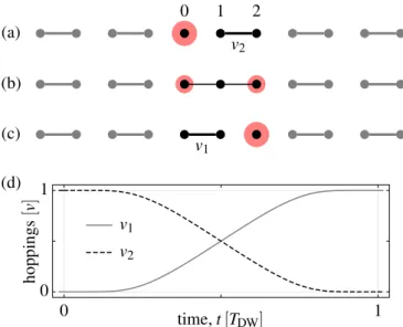
FIG. 1. Adiabatically moving a domain wall and the localized zero-energy state it supports, in a fully dimerized SSH chain. Red circles depict the particle density of the localized state. The sequence (a)-(b)-(c) shows how to move the domain wall and the localized state by two sites. The domain-wall movement timeTDWis the time window between (a) and (c). (d) Time dependence of the hopping amplitudes; see Eq. (3).
The elementary step of this domain-wall motion is illus- trated in Fig.1. Figure1(a)shows a fully dimerized SSH chain with a domain wall that is the isolated site. We consider the three-site black subset of the chain, labeled with 0, 1, and 2, and disregard the remaining gray part for our discussion. The Hamiltonian describing this three-site block reads
H(t)=v1(t)|1 0| +v2(t)|2 1| +H.c., (1) with v1(t =0)=0 and v2(t =0)=v>0 as shown in Fig.1(a). Here, each ket denotes the state localized at the cor- responding site. We consider real-valued hopping amplitudes in most of this work, unless noted otherwise. It is a simple fact that the domain wall, i.e., site 0 in Fig. 1(a), which is disconnected from the rest of the chain, supports a perfectly localized zero-energy mode|0. This state is depicted as the red circle.
The domain wall together with this localized state can be moved adiabatically by, e.g., increasing the hoppingv1to the valuev, and decreasing the hoppingv2to zero simultaneously.
Figures 1(a), 1(b), and 1(c) show the initial configuration, an intermediate configuration, and the final configuration, respectively. As a result of these changes, the domain wall has moved from site 0 [Fig.1(a)] to site 2 [Fig.1(c)]. Furthermore, if these hopping-amplitude changes are done adiabatically, then the state|0evolves to the state − |2; that is, the zero mode moves two sites to the right and acquires a minus sign. This is a direct consequence of the simple fact that the HamiltonianHhas a zero-energy eigenstate
|ψ = v2|0 −v1|2 v21+v22
. (2)
The prefactor −1 in front of|2 above is not supplemented by a dynamical phase factor: the dynamical phase vanishes
because the state |ψ is a zero-energy eigenstate for all intermediate times. Note that this instantaneous zero-energy state generally has some weight on sites 0 and 2, but has no weight on site 1. For example, in the intermediate time step whenv1=v2, this zero-energy state is evenly distributed on the sites 0 and 2, as shown in Fig.1(b).
The actual time dependencies of the hopping amplitudes v1 andv2 can have various forms; the resulting dynamics is independent of the details in the adiabatic limit. The simplest option could be to use linear ramps for each hopping ampli- tude. In what follows, we will use a smooth, exponential time dependence instead, which is expected to suppress leakage from the zero-energy subspace that arises due to the finite (noninfinite) time durationTDWof the domain-wall movement [17,23]. The hopping amplitudes are changed in time as
v1(t)=vχ(t/TDW), (3a) v2(t)=v[1−χ(t/TDW)], (3b) where the pulse shape functionχis defined as
χ(x)= e−1/x
e−1/(1−x)+e−1/x. (4) In Eq. (3), we introduced the domain-wall movement time TDW, which is the time used to move the domain wall by two sites [i.e., from (a) to (c) in Fig.1]. The time-dependent hopping amplitudes in Eq. (3) are shown in Fig.1(d).
Importantly, the result of this adiabatic deformation of the Hamiltonian, i.e., that the state|0 develops to the state
− |2, does not depend on the actual protocol used to tune the hopping amplitudes in time. As seen directly from Eq. (2), this final state is guaranteed provided that at least one ofv1 andv2is nonzero for all times, and that the final value ofv1is positive.
III. EXCHANGE OF ZERO-ENERGY MODES IN A Y JUNCTION PROVIDES AY GATE
In this section, we propose the SSH Y-junction setup and a braiding protocol, and numerically solve the time-dependent Schrödinger equation to show that adiabatic braiding leads to a perfectY gate if the SSH chains of the junction are fully dimerized. Topological protection is not addressed here; that we will do in the subsequent sections.
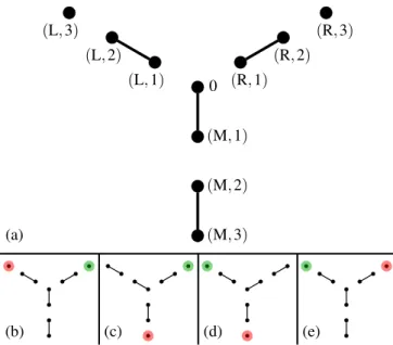
The SSH Y junction and the braiding protocol are illus- trated in Fig. 2. The single-particle tight-binding Hamilto- nian at the initial stage of the braiding protocol is shown in Fig. 2(a). This junction is formed by three SSH chains, connected via a central site. We denote the three chains by L, R, and M, according to their location in the figure. For simplicity, we consider cases where the three chains have the same lengthNc; the figure corresponds to chain lengthNc=3.
The tight-binding Hamiltonian of this Y junction reads
H=
c∈C Nc−1
m=1
vc,m(|c,m c,m+1| +H.c.) +
c∈C
vc,0(|0 c,1| +H.c.), (5)
FIG. 2. Braiding in a Y junction constructed from three fully dimerized SSH chains. (a) shows the initial configuration and the labels associated to the sites. In (b)–(e), the colored sites (red, green) depict the zero-energy edge modes. These edge modes are exchanged by adiabatically moving the domain walls supporting them, follow- ing the scheme in Fig.1. (b) depicts the initial configuration,t=0.
(c) and (d) depict the two intermediate configurations when the zero- energy modes are localized at the outer ends of the chains,t=3TDW
and t=6TDW, respectively. (e) denotes the final configuration at t=9TDW: the Hamiltonian is the same as the initial one (b), but the edge modes have been exchanged.
where C= {L,R,M} is the set of chain indices, and m is the site index within a given chain. According to Fig.2(a), the state localized on the central site is denoted by
|0, and the state localized on themth site on chaincis denoted by|c,m.
Figure 2(a) depicts a certain configuration of hopping amplitudes: the hopping amplitudes shown as black lines are set to v (e.g., vM,0=v); all other hopping amplitudes are set to zero (e.g.,vM,1=0). The Hamiltonian corresponding to Fig. 2(a) has a two-dimensional zero-energy subspace, spanned by the states |L,3 [depicted as the red circle in Fig.2(b)], and|R,3[depicted as the green circle in Fig.2(b)].
These two edge sites can be considered as defects giving rise to a two-dimensional zero-energy subspace.
We propose to perform theY gate in this two-dimensional subspace by exchanging the two defects adiabatically. The first stage of the exchange consists of moving the red defect by repeating the elementary step introduced in Fig. 1 (i.e., moving the domain wall by two sites) three times, to achieve the configuration in Fig.2(c); the second and third stages are analogous, yielding the configurations in Figs.2(d)and2(e), respectively. After the third stage, the Hamiltonian returns to its initial form, but the two defects and the two localized zero-energy modes have been exchanged. Actually, since it took an odd number of steps (three) to move the green defect, the state |R,3 evolves into the state − |L,3, picking up a minus sign. In contrast, it took an even number of steps (six) to move the red defect; hence the state|L,3evolves into the
state |R,3, with no sign change. As a result, the braiding induces a gate
Y =
0 −1
1 0
= −iσy (6) in the basis (|φ1,|φ2)≡(|L,3,|R,3). It is clear that a similar braiding operation in a Y junction with an arbitrary odd chain lengthNc=1,3,5, . . . yields the same gate. Note that the elementary version of this scheme, corresponding to Nc=1, was studied in Refs. [10,24].
The braiding should provide an exactY gate in the adia- batic limit, i.e., for infinitely long braiding timeT. In the rest of this section, we study whether that is true, and how the finite braiding time affects the accuracy of the gate. We characterize the accuracy using the concept of average fidelity. The time evolution during the full braiding sequence is described by the propagator of the time-dependent Schrödinger equa- tion, that is expressed by the well-known time-ordered (T) exponential
U(T)=T exp
−i
¯ h
T 0
dt H(t)
. (7)
The effect of the braiding on the two-dimensional zero-energy subspace is described by the propagator projected onto that subspace, which we will refer to as theoverlap matrix:
O(T)=
φ1|U(T)|φ1 φ1|U(T)|φ2 φ2|U(T)|φ1 φ2|U(T)|φ2
. (8)
As stated above, we expect that braiding is perfect in the adiabatic limit, that is, limT→∞O(T)=Y.
For a given initial state|φ in the two-dimensional zero- energy subspace, the fidelity of the braiding operation can be described by the probability of finding the state after the braiding operation in the final state of the idealized operation:
f(φ,T)= |φ|Y†O(T)|φ|2. Therefore, the overall quality of the gate can be described by the average of the above fidelity f(φ,T) for all initial statesφ in the two-dimensional zero- energy subspace, yielding [25]
F = 16[Tr(O†O)+ |Tr(Y†O)|2], (9) where the argument T of F(T) and O(T) was omitted for brevity. Theaverage fidelity is F =1 if the overlap matrix Ois equivalent to the ideal gateY, and 0F <1 otherwise.
Hence, we characterize the error of the braiding protocol using theinfidelity
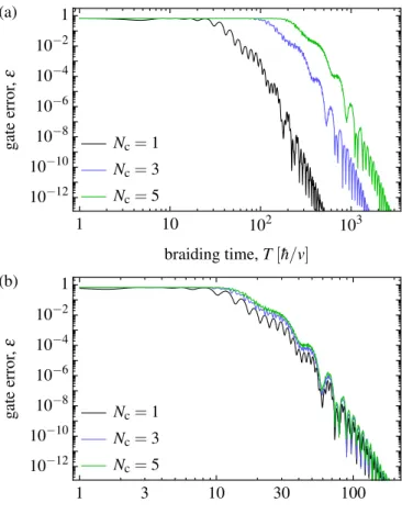
ε(T)=1−F(T). (10) The error ε, obtained from a numerical solution of the time-dependent Schrödinger equation, is shown in Fig.3(a), as a function of braiding timeT, for three different lengths Nc=1,3,5 of the chains forming the Y junction. For short braiding times, errors are caused by the nonadiabatic character of the driving. Even though there are oscillations on each curves, the error seems to converge to zero as the braiding time is increased, confirming expectations. Furthermore, the results suggest that it is possible to reach any targeted error level, but the longer the chain, the longer the braiding time required for that. Finally, an interesting scaling property is demonstrated in Fig.3(b), where the data set is the same as in Fig.3(a), but the
FIG. 3. Error of theY gate in the fully dimerized SSH Y junction due to the finite braiding time. (a) Gate error [infidelity; see Eq. (10)]
is shown as the function of braiding time. (b) Gate error of panel (a) is shown, rescaled, as the function of the timeTDWrequired for a single step of domain-wall motion. Errors are induced due to the nonadiabatic character of the braiding; hence they get suppressed as the braiding time is increased.
horizontal axis is rescaled to show the domain-wall movement timeTDW instead of the braiding time. With this scaling, the three data sets show a very similar behavior, indicating that the velocity of the domain-wall motion is the factor determining the gate error.
Up to now, we have studied a simple protocol that performs a quantum gate in a degenerate subspace of a Hamiltonian. Is this gate robust in any sense? Is it robust if we relax the fully dimerized character of the Y junction that was assumed in this section? Is it robust if we introduce disorder? We address these questions in what follows.
IV. NUMERICAL DEMONSTRATION OF TOPOLOGICAL PROTECTION
In the previous section, we assumed that the SSH Y junction is in a fully dimerized configuration, apart from the region of the domain wall that is being moved. Here, we consider a case when the system is not in the fully dimerized configuration, and in addition, random hopping disorder with real-valued hopping amplitudes is also introduced. In this case, chiral symmetry and the time-reversal symmetry of the setup are still preserved. We show that the Y gate is
FIG. 4. SSH Y junction away from the fully dimerized limit with hopping disorder. Structure of the initial and final Hamiltonian of the braiding protocol is depicted. Solid (dashed) lines are strong (weak) hopping amplitudes, all having random components. In the initial and final configuration shown here, the defects residing on sites (L,3) and (R,3) are isolated from the rest of the system.
topologically protected, i.e., becomes perfect, insensitively to the disorder, in the adiabatic limit and in the limit of large system size (Fig.5). In contrast, as we also show below, there is no such protection when disorder on the on-site energies of the lattice is introduced (Fig.6) or when the hopping disorder consists of complex-valued hopping amplitudes (Fig.7).
A. TheYgate is robust against real-valued hopping disorder We consider a setup similar to Fig. 2(a); see Fig. 4.
The setup in Fig. 4 is also described by the Hamiltonian (5). Similarly to the case of Fig. 2(a), we keep all on-site energies zero and use real-valued time-dependent hopping amplitudes. In this case, however, the hopping amplitudes are not tuned between 0 andv, but between a minimal valuevminc,m and a maximal value vcmax,m instead. As indicated in Fig. 4, the defect sites are isolated; i.e., we choosevLmin,2 =vRmin,2 =0 andvL,2max=vRmax,2 =v. However, we introduce disorder in all further hopping amplitudes depicted in Fig.4:
vminc,m =w+δvc,m, (11a) vcmax,m =v+δvc,m. (11b) Here,w<vis chosen, andδvc,mis a Gaussian random vari- able with zero mean and standard deviationsv<v. A finite (nonzero) value ofwcorresponds to the nonfully dimerized case when the defect-bound states spread out and are more delocalized compared to the fully dimerized limit. Same be- havior is caused by the hopping disorder in a random fashion.
Apart from this difference in the minimal and maximal values of the hopping amplitudes, the braiding scheme is defined in complete analogy with that in Sec.III. For example, the first elementary step in moving the red zero mode and the associated defect is induced by
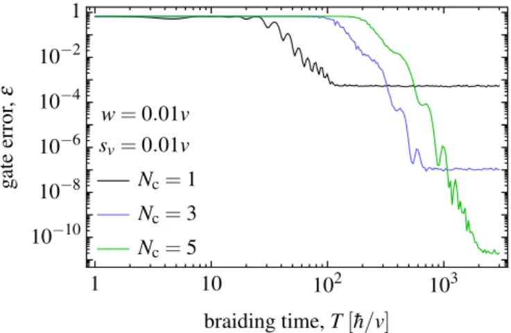
vL,2(t)=vχ(t/TDW), (12a) vL,1(t)=v+δvL,1−(v−w)χ(t/TDW). (12b) The robustness of the Y gate, i.e., its resilience to the real-valued hopping disorder in the adiabatic and long-chain limit, is shown in Fig.5. The zero-energy subspace of the initial Hamiltonian (which equals the final Hamiltonian) is
FIG. 5. Error of theY gate in a nondimerized SSH Y junction with real-valued hopping disorder. Disorder-averaged gate error [in- fidelity; see Eq. (10)] is shown as a function of braiding timeT for three different chain lengthsNc. The error saturates for long braiding times in each case, and the error minimum decreases exponentially as the chain length is increased, despite the presence of disorder; this indicates topological protection. Each curve is an average for 1000 random realizations.
spanned by the two completely localized states |L,3 and
|R,3, and therefore we can characterize the gate fidelity using the infidelityε=1−F introduced earlier in Eq. (10).
In Fig. 5, we show the errorε of the braiding-basedY gate as a function of braiding time T, for three different chain lengthsNc. Furthermore, we setw=0.01vand the disorder strength tosv =0.01v, and each curve is an average for 1000 different disorder realizations. The first key feature of these results is that the gate error approaches its minimum value for long braiding times, when braiding is adiabatic, as expected.
In fact, the error saturates and forms a plateau in all three cases. The second key feature is that the minimum value of the error, i.e., the height of the plateau, decreases exponentially as the chain length is increased. Here we do not show it, but a finitewor a hopping disorder with a finitesvleads separately to the saturation of the error. These results clearly demon- strate the robustness of theY gate against hopping disorder even away from the fully dimerized limit. As we show in Sec.V, this resilience can be understood as topological pro- tection, arising as a joint consequence of chiral symmetry, time-reversal symmetry (both of which are preserved in the presence of real-valued hopping disorder), and the spatial separation of the zero modes during their exchange.
B. TheYgate is not robust against on-site disorder The braiding-basedY gate is not resilient to on-site energy disorder. This is illustrated by Fig. 6. For simplicity, in this subsection we switch off hopping disorder (sv =0) and take w=0. To study the effect of on-site disorder, we supplement the Y-junction Hamiltonian (5) with the on-site term. That is, we consider dynamics governed by the HamiltonianH= H+Honsite, where the second term is defined as
Honsite=
j
uj|j j|. (13)
FIG. 6. Error of theY gate in the presence of on-site disorder.
Disorder-averaged gate error [infidelity; see Eq. (10)] is shown as a function of braiding timeT for three different chain lengthsNc. The Y gate is not robust against on-site disorder: the gate error saturates at a high value for long braiding times, at a value independent of the chain length. Each curve is an average for 1000 random realizations.
Here, the parameters uj are random on-site energies with zero mean and, in what follows, with a standard deviation su=0.01v. The sum in Eq. (13) goes for all sites except the two sites supporting the two defects att =0, that is, except (L,3) and (R,3).
The numerically obtained gate error as a function of braiding time is shown in Fig. 6 for three different chain lengths. To obtain these data, we have numerically solved the time-dependent Schrödinger equation of the HamiltonianH defined above. Each curve in Fig. 6 is an average for 1000 random disorder realizations. The key differences in compar- ison to the case with real-valued hopping disorder in Fig.5 are as follows. (i) The gate error is always much larger in the presence of on-site disorder than in the presence of real-valued hopping disorder. (ii) For real-valued hopping disorder, the minimal error gets smaller for longer chain length; for on-site disorder the trend is the opposite. (iii) For on-site disorder, the error does not have a minimum in the adiabatic, long-braiding- time limit, but at an intermediate braiding time. In short, a key reason behind these differences is that the on-site disorder opens a minigap in the spectrum between the two zero-energy eigenstates; the corresponding dynamical phase picked up by the states during the time evolution depends explicitly on the random disorder configuration and the braiding time, and hence it leads to dephasing in the adiabatic limit.
C. TheYgate is not robust against complex-valued hopping disorder
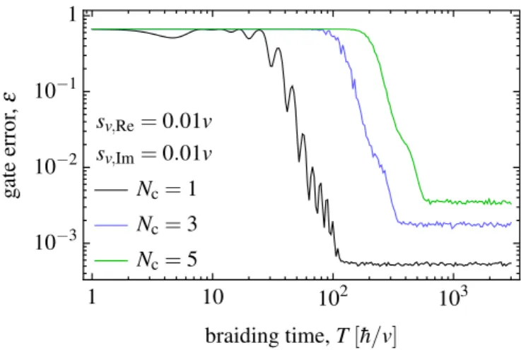
The braiding-based Y gate is not resilient to hopping disorder, if the hopping amplitudes can take complex values (Fig.7). To show this, we use the same parametrization of the hopping amplitudes as introduced in Eqs. (11) and (12), with the only difference that the random componentsδvc,mof the hopping amplitudes are complex. In particular, we consider the case when the real and imaginary parts of δvc,m are identically distributed normal random variables, with standard
FIG. 7. Error of the Y gate in the presence of complex- valued hopping disorder. Disorder-averaged gate error [infidelity; see Eq. (10)] is shown as a function of braiding timeT for three different chain lengths Nc. The error saturates at a value for long braiding times, but that value increases as the chain length is increased. This indicates that theY gate is not robust against complex-valued hop- ping disorder. Each curve is an average of 1000 random realizations.
deviationssv,Re=sv,Im=0.01v. Furthermore, we setw=0 for simplicity.
The numerically obtained gate error as a function of braid- ing time is shown in Fig.7for three different chain lengths.
The key feature of the results is that the error saturates at a plateau for each chain length, similarly to the case of real- valued hopping disorder, but the height of the plateau actually grows as the chain length is increased. This is in contrast to the case of real-valued hopping disorder, where we have seen that the error plateau height decreases exponentially as the chain length is increased. Hence, the results in Fig.7indicate that theY gate is not protected against complex-valued disorder.
V. TOPOLOGICAL PROTECTION IS ENSURED BY CHIRAL SYMMETRY, TIME-REVERSAL SYMMETRY,
AND SPATIAL SEPARATION OF THE ZERO MODES In the previous section, we have demonstrated that the braiding-based Y gate is robust against real-valued hop- ping disorder, but not robust against on-site disorder, neither against complex-valued hopping disorder. Here, we prove that this robustness is due to topological protection, and arises as a joint consequence of chiral symmetry, time-reversal sym- metry, and the spatial separation of the defects supporting the zero-energy modes.
As the first step of the proof, we introduce two sublattices:
sublattice A contains the sites with an odd ordinal number, e.g., (L,3), (C,1), etc., whereas sublatticeBcontains the rest of the sites. Then, the matrix
C=
j∈A
|j j| −
j∈B
|j j| (14)
is a chiral symmetry [16] of the Hamiltonian, that is, CHC−1= −H. This is due to the fact that all matrix ele- ments of the Hamiltonian are connecting sites of different sublattices. Note that there are more A sites than B sites:
we have NA=NB+2, where NA (NB) is the number of A
(B) sites; in the example of Fig. 2(a), NA=6 and NB=4.
As a consequence of this mismatch and the chiral symmetry, the Hamiltonian has two degenerate zero-energy eigenstates, as we prove in the Appendix. This zero-energy subspace is different from the one formed by the edge states of a single SSH chain in the topological phase [16]: in the latter case, the edge states can hybridize and a nonzero minigap can open between the bonding and antibonding hybrid states, whereas the defect-bound states in our Y junction are at exactly zero energy, as a consequence of their dark-state character (see the Appendix).
Our second step is to show that the overlap matrix O defined in Eq. (8) is real-valued if the Hamiltonian, dur- ing the whole duration of the braiding, maintains its chiral symmetry and real-valuedness. To see this, we factorize the propagatorU in n+1 discrete short time steps of duration τ =T/(n+1), that is, U =UnUn−1. . .U1U0, where Uj = exp [−iH(jτ)τ/h]. With this discrete representation of the¯ propagator, we find
Oi j= φi|U|φj (15a)
= φi|C(CUnC). . .(CU0C)C|φj (15b)
= φi|CUn∗. . .U0∗C|φj (15c)
= φ∗i|Un∗. . .U0∗|φ∗j =Oi j∗. (15d) To obtain (15b) from (15a), we inserted unity in the form of C2 =1 before and after each time step. To obtain (15c) from (15b), we used the chiral symmetry of the Hamiltonian as well as its real-valued character, which imply
CUjC=Cexp[−iH(jτ)τ/h]C¯ (16a)
=exp[iH(jτ)τ/h]¯ (16b)
=exp[iH∗(jτ)τ/h]¯ =Uj∗. (16c) To obtain (15d) from (15c), we used the fact that the basis vectors|φi are their own chiral partners, C|φi = |φi, and that they are real-valued.
As the third step, we argue that in the limit of adiabatic braiding, the overlap matrixOis not only real-valued but also unitary. To see that, we have to assume that during the braiding procedure, the zero-energy subspace of the HamiltonianH(t) is exactly twofold degenerate for all times, that is, that no lower-lying or higher-lying energy level ever collides with the two zero-energy levels we focus on. Then, the notion of adiabaticity is indeed well-defined, and there is no leakage from the zero-energy subspace if the braiding is adiabatic, guaranteeing the unitary nature of the overlap matrix. All real-valued 2×2 unitary matrices (i.e., the 2×2 orthogonal matrices) can be written in one of these forms:
O+(θ)=
cosθ sinθ
−sinθ cosθ
, (17a)
O−(θ)=
cosθ sinθ sinθ −cosθ
, (17b)
where θ is a real angle. One difference between these two classes is their determinant being+1 and−1, respectively.
In the last, fourth step, we utilize that the two localized zero-energy eigenstates are spatially exchanged during the
braiding protocol. As long as their spatial separation is en- sured by using long enough chains, the braiding procedure will move the first zero mode to the position of the second one, and move the second one to the position of the first one.
Therefore, the overlap matrix is off-diagonal, allowing only four different configurations:
O+(π/2)=
0 1
−1 0
=iσy, (18a)
O+(−π/2)=
0 −1
1 0
= −iσy, (18b)
O−(π/2)= 0 1
1 0
=σx, (18c)
O−(−π/2)=
0 −1
−1 0
= −σx. (18d) In conclusion, the characteristics of our braiding procedure restrict the overlap matrix of the braiding operation to the four options shown in Eq. (18). We know that in the fully dimerized limit, we have a Y gate, see Eq. (6), which corresponds to Eq. (18b). Therefore, in the case of hopping disorder, when the Hamiltonian is adiabatically connected to the fully dimerized limit, the overlap matrix in the adiabatic limit and limit of long chains must beY as well. We emphasize that we have used the chiral symmetry and the real-valued nature of the Hamiltonian to arrive to this conclusion. In what follows, we will refer to the real-valued nature of the Hamiltonian by saying thatH has time-reversal symmetry. In this case, time-reversal sym- metryT is represented by the complex conjugation,T =K, this time-reversal symmetry squares toT2=1, and the real- valued nature of H can be written asKH K−1=H. Hence, our system falls into the Cartan symmetry class BDI [26].
A follow-up question is whether the other three overlap matricesiσy,σx,−σx can be realized with braiding-like pro- cesses. The answer is yes for iσy: one can achieve this by reversing the steps shown in Figs. 2(b)–2(e), by moving the right zero mode first.
Consider now further adiabatic deformations of the Hamil- tonian, where each mode ends up at its original position.
Arguments similar to those used above imply that in such cases, the overlap matrix is one of these four diagonal, real unitary 2×2 matrices: 1, σz, −1, −σz. It is clear that in our setup, 1 can be realized by any adiabatic deformation of the Hamiltonian that does not braid the zero-mode positions, and−1=(−iσy)(−iσy)=(iσy)(iσy) can be realized, e.g., by repeating the same braiding twice. Below, we show that the remaining gatesσx,−σx,σz, and−σzcannot be realized.
All the quantum gates discussed above are topologically protected in the sense that their form depends only on the topology of the world lines of the zero modes. To formalize that a bit more, let us discuss arbitrary cyclic adiabatic defor- mations that start and end with two isolated zero modes (as done in the previous section), and where the spatial separation of the zero modes is guaranteed throughout the deformation.
Then, the world lines of the two zero modes for a given cyclic deformation are characterized by a certain element of the braid groupB2, which is equivalent to the group of integer numbers Zwith addition as the group operation: a clockwise exchange contributes +1, an anticlockwise exchange contributes −1.
FIG. 8. An SSH double Y junction allowing for braiding-based non-Abelian operations. Three defects (1, 2, 3) define a three- dimensional zero-energy subspace. The operation obtained by ex- changing defects 1 and 2 first and 2 and 3 second is different from the operation obtained by doing these two steps in the reversed order.
The set of the four quantum gates 1,Y,Y2= −1,Y3= −Y, equipped with matrix multiplication as the group operation, form a groupGY equivalent to the cyclic group of order 4, that is,Z4. Our model therefore provides a two-dimensional representationρof the braid groupB2in terms of the quantum gates, namelyρ: B2→GY,n→Yn.
The braid group on two strands,B2, is Abelian; hence the image of any of its representation must be an Abelian group as well. On the one hand, this is reassuring sinceGY is Abelian.
On the other hand, it also implies that±σx and±σz cannot be generated by braiding two defects, since their inclusion in the image of the representation would make the image non- Abelian.
Nevertheless, it is straightforward to find generalizatons of our setup, where more defects are present, and the quantum dynamics induced by the various braidings of the defects generates a group of matrices that is non-Abelian. An example with three defects is shown in Fig.8; here the world lines of the defects are described by the braid group on three strands, B3. The adiabatic counterclockwise exchange of the defects 1 and 2 results in the overlap matrix
Y12=
⎛
⎝0 −1 0
1 0 0
0 0 1
⎞
⎠, (19)
whereas the counterclockwise exchange of defects 2 and 3 results in
Y23=
⎛
⎝1 0 0
0 0 −1
0 1 0
⎞
⎠. (20)
Clearly, the matricesY12andY23do not commute.
VI. DISCUSSION
Experimental realizations.The topologically protectedY gate proposed above is presented in the context of a nonin- teracting nonsuperconducting tight-binding model. Because of the simplicity of the model, we expect that the braiding dynamics simulated here can be realized in experiments. Two suitable experimental platforms are tunnel-coupled optical waveguides [18,19], and cold atomic systems where quantum states form a highly tunable tight-binding lattice in momen- tum space [20,21]. The role of hopping disorder has already been studied experimentally in these setups [19,21].
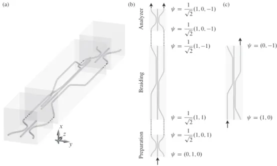
Here, we discuss the optical waveguide array where our model can be realized, and the effect of the braiding operation could be observed. The setup, shown in Fig.9(a), is inspired by a similar one shown in Fig. 2(a) of Ref. [27]. This is a realization of our tight-binding model with 4 sites, that is, withNc=1.
The waveguide array shown in Fig. 9 can be used to confirm that our braiding protocol provides a Y gate. The experiment consists of two stages. In the first stage, only the braiding waveguide array is used [see Fig. 9(c)]. This is an array of four waveguides, representing the four sites in our tight-binding model withNc=1. The spatial distance between the waveguides is modulated along the longitudinal, zdirection, mimicking the time-dependent modulation of the tunnel coupling in our tight-binding model [27]. Therefore, if a laser beam is injected in one of the two input waveguides, say, the left one [bottom arrow of Fig. 9(c)], then the laser beam will come out from the right output waveguide [top arrow of Fig. 9(c)] as the result of braiding. Of course, this measurement is not revealing theπ phase shift of the output beam, so it is not able to distinguish between theX gate and a Y gate, for example.
To make a phase-sensitive measurement, that is, to dis- tinguish between X-gate and Y-gate scenarios, one should do a second stage of the experiment, where the braiding segment is supplemented by a preparation and an analyzer segment of waveguides [see Fig. 9(b)]. These two segments are identical, but they serve different purposes. The structures are left-right symmetric, and serve as perfect beam splitters with no phase difference between the two output beams. For example, the preparation stage is used to convert an incident laser beam entering the middle waveguide [bottom arrow in Fig.9(b)] to a 50-50 superposition output on the left and right waveguides, with no phase difference. Then, this superposed laser beam will go through the braiding segment performing aY gate, which will result in a similar balanced superposition on the output ports, but will introduce aπ relative phase shift between the split beams. Finally, the output of the braiding segment is fed into the analyzer segment, and due to the destructive interference arising from the π-phase difference, the beam will not penetrate the middle waveguide of the analyzer but will come out with 50-50 intensity in its left and right output ports.
In contrast, if the braiding segment would produce an X gate, then the output beam coming from the analyzer would come from the middle output port due to constructive interfer- ence. Hence, observing a 50-50 intensity in the left and right output ports of the setup in Fig. 9 is a fingerprint of theY gate. Note this two-stage experiment could be refined to allow for a complete process tomography. Also, based on earlier experiments, extending this setup to multiple waveguides in the presence of hopping disorder seems feasible [13,19].
Numerical calculations. In all our results presented above, the overlap matrix was calculated by discretizing the time evolution operator, assuming a time-independent Hamiltonian for each time step. All numerical results were obtained by splitting the braiding time T to 1000 time steps of equal duration. We performed a convergence test by halving the time step (doubling the number of time steps). We have compared the error vs braiding time curves for the ordered cases as
FIG. 9. Optical waveguide structure for the demonstration of a braiding-basedY gate. (a) Three-dimensional view of the setup. The three segments (bottom: preparation, middle: braiding, top: analyzer) are separated for better visualization, but they might have direct contact in a real device. (b) Details of the phase-sensitive measurement. Preparation segment creates a 50-50 superposition on the outer waveguides with no phase difference. Braiding segment acts as aY gate, shifting the relative phase between the two beams byπ. Due to this phase shift and the corresponding complete destructive interference, the beam does not enter into the middle waveguide as passing through the analyzer segment, but comes out with 50-50 intensity in the left and right outputs. (c) Braiding segment. Beam injected in left waveguide comes out from right output as a result of braiding. This measurement alone cannot distinguish between theX gate and aY gate. Vectorψdescribes the input and output beam amplitudes at each segment.
well as a few realizations of disorder, without observing any significant difference between the curves obtained with 1000 time steps and those with 2000 time steps.
VII. CONCLUSION
In conclusion, we have proposed a single-particle sys- tem, the SSH Y junction, where braiding of defects and the corresponding zero modes provides topologically protected quantum gates. The topological protection of the gates arises as the joint consequence of the chiral and the time-reversal symmetries of the Hamiltonian, and the spatial separation of the zero modes. Cyclic adiabatic deformations of the Hamilto- nian establish a group representation between the braid group and the available group of quantum gates, the latter being Abelian when there are only two defects in the system, but non-Abelian if at least three defects are present. Even though the model system introduced here will probably not be used in practical topological quantum computing schemes, it does stand out from earlier schemes because of its conceptual sim- plicity, and its strong potential for experimental realization.
ACKNOWLEDGMENTS
We thank M. Droth, M. Kremer, L. Teuber, A. Szameit, and D. Varjas for useful discussions, and G. Takács for computa- tional resources. This research was supported by the National Research Development and Innovation Office of Hungary within the Quantum Technology National Excellence Pro- gram (Project No. 2017-1.2.1-NKP-2017-00001), and Grants No. FK124723, No. K115575, and No. K115608. This work
was completed in the ELTE Institutional Excellence Program (1783-3/2018/FEKUTSRAT) supported by the Hungarian Ministry of Human Capacities. O.L. was supported by the Bolyai and Bolyai+scholarships of the Hungarian Academy of Sciences.
APPENDIX: ZERO-ENERGY EIGENVECTORS OF A CHIRAL SYMMETRIC HAMILTONIAN
WITH SUBLATTICE IMBALANCE
In the main text, we described simple single-particle Hamiltonians with chiral symmetry, where the two sublat- tices contained a different number of sites, NA =NB+2.
We claim that such Hamiltonians have a twofold-degenerate zero-energy subspace. Here we provide a simple proof.
Take a Hamiltonian of size dimensionNA+NB, with the special form
H =
0 V V† 0
, (A1)
where V is an NA×NB matrix with complex entries, and couples the two sublattices, A and B. Without the loss of generality, assumeNA>NB. For example, in the model shown in Fig.2(a), we haveNA=6 and NB =4. Any such matrix V can be factorized asV =LW R†, where L is an NA×NA
unitary matrix,Ris anNB×NB unitary matrix, andW is an NA×NBrectangular diagonal matrix, meaning that all entries but the ones of the formWi,iare zero; this is known assingular value decomposition. Using this decomposition, it is easy to
see that H =
L 0
0 R
U
0 W W† 0
H˜
L† 0 0 R†
U†
, (A2)
where U is a unitary matrix (not to be confused with the propagator in the main text).
The spectrum ofHand ˜His the same, since they are related by the unitary transformationU. From the structure of the rectangular blockW discussed above, it is clear that ˜H has
NA−NB zero eigenvalues, and hence that is also true forH.
That concludes the proof.
Note that this claim and its generalizations are sometimes called the dark-state theorem, and the eigenstates ofH be- longing to the zero-energy subspaces are calleddark states.
See also Ref. [28] for a related discussion. Furthermore, these considerations can be straightforwardly generalized to the case when the two diagonal blocks of H are not zero but proportional to the identity matrix, with potentially different proportionality constants.
[1] C. Nayak, S. H. Simon, A. Stern, M. Freedman, and S. Das Sarma,Rev. Mod. Phys.80,1083(2008).
[2] J. K. Pachos,Introduction to Topological Quantum Computation (Cambridge University Press, Cambridge, UK, 2012).
[3] D. A. Ivanov,Phys. Rev. Lett.86,268(2001).
[4] J. Alicea, Y. Oreg, G. Refael, F. von Oppen, and M. P. A. Fisher, Nat. Phys.7,412(2011).
[5] A. Y. Kitaev,Ann. Phys.303,2(2003).
[6] V. Mourik, K. Zuo, S. M. Frolov, S. R. Plissard, E. P. A. M.
Bakkers, and L. P. Kouwenhoven, Science 336, 1003 (2012).
[7] R. M. Lutchyn, E. P. A. M. Bakkers, L. P. Kouwenhoven, P.
Krogstrup, C. M. Marcus, and Y. Oreg,Nat. Rev. Mater.3,52 (2018).
[8] J. Klinovaja and D. Loss, Phys. Rev. Lett. 110, 126402 (2013).
[9] Z. Song,arXiv:1712.07696.
[10] M. Droth,arXiv:1901.03276.
[11] C.-Y. Hou, C. Chamon, and C. Mudry,Phys. Rev. Lett. 98, 186809(2007).
[12] T. Iadecola, T. Schuster, and C. Chamon,Phys. Rev. Lett.117, 073901(2016).
[13] A. J. Menssen, J. Guan, D. Felce, M. J. Booth, and I. A.
Walmsley,arXiv:1901.04439.
[14] S. Bariši´c,Phys. Rev. B5,932(1972).
[15] W. P. Su, J. R. Schrieffer, and A. J. Heeger,Phys. Rev. Lett.42, 1698(1979).
[16] J. K. Asbóth, L. Oroszlány, and A. Pályi,A Short Course on Topological Insulators(Spinger, Berlin, 2016).
[17] M. Sekania, S. Plugge, M. Greiter, R. Thomale, and P.
Schmitteckert,Phys. Rev. B96,094307(2017).
[18] A. Szameit and S. Nolte,J. Phys. B: At. Mol. Opt. Phys.43, 163001(2010).
[19] L. Martin, G. D. Giuseppe, A. Perez-Leija, R. Keil, F. Dreisow, M. Heinrich, S. Nolte, A. Szameit, A. F. Abouraddy, D. N.
Christodoulides, and B. E. A. Saleh,Opt. Express 19,13636 (2011).
[20] E. J. Meier, F. A. An, and B. Gadway,Nat. Commun.7,13986 (2016).
[21] E. J. Meier, F. A. An, A. Dauphin, M. Maffei, P. Massignan, T. L. Hughes, and B. Gadway,Science362,929(2018).
[22] F. Mei, G. Chen, L. Tian, S.-L. Zhu, and S. Jia,Phys. Rev. A 98,012331(2018).
[23] C. Knapp, M. Zaletel, D. E. Liu, M. Cheng, P. Bonderson, and C. Nayak,Phys. Rev. X6,041003(2016).
[24] R. G. Unanyan, B. W. Shore, and K. Bergmann,Phys. Rev. A 59,2910(1999).
[25] L. H. Pedersen, N. M. Moller, and K. Molmer,Phys. Lett. A 367,47(2007).
[26] C.-K. Chiu, J. C. Y. Teo, A. P. Schnyder, and S. Ryu,Rev. Mod.
Phys.88,035005(2016).
[27] M. Kremer, L. Teuber, A. Szameit, and S. Scheel, arXiv:1902.02559.
[28] J. R. Morris and B. W. Shore,Phys. Rev. A27,906(1983).