P W A H R E N
S U M M A R Y
An oscilloscope sweep circuit with automatic amplitude and sweep speed regulation is described. A change in the triggering frequency causes a proportional change in sweep speed. The amplitude is kept constant.
The control method described here can be used for any time base circuits employing RC or RL timing networks.
It is sometimes desirable to see a fixed number of cycles on the cathode ray tube of an oscilloscope when the input frequency varies over a fairly wide range. This is often the case, e. g. in studies of rotating machinery.
The sawtooth waveform from an oscilloscope sweep generator is in the simplest cases realised with the help of an RC circuit. The capacitance is charged or dischar
ged via the resistor. At the end of the period some kind of switch is used to restore the initial conditions. The switch is triggered by the incoming variable frequency, usually from the Y amplifier of the oscilloscope.
Most advanced oscilloscopes have some device for inactivating the discharge triggering signal during the sweep, thus maintaining a constant sweep amplitude.
This, however, means that the number of cycles on the screen will vary with the frequency, necessitating readjustment of the sweep speed controls when the frequency of the incoming signal changes.
den Hartog and Muller 1947 showed a way to avoid this with their modification of Puckle's time base [ 1 , 2 ] .
In Puckle's time base a capacitor is charged from a constant current generator and discharged through a variant of the multivibrator. If the charging current is held constant, the output amplitude varies as the synchronizing frequency is altered, den Hartog and Muller measured the peak value of the sawtooth with a diode, filtered the diode output and used it to regulate the constant current generator, thus keeping the sawtooth amplitude almost constant. This considerably improved the synchronizing properties of the circuit and made it possible to show the same number of cycles on the oscilloscope screen in a frequency range greater than 1:10. The charging current is proportional to the sweep frequency, which can thus easily be indicated with a moving-coil instrument.
Many variations of this amplitude-regulating principle are possible.
As briefly pointed out in the original paper, it is not necessary to rectify the output voltage to obtain a regulating signal.
1
R o y a l I n s t i t u t e of T e c h n o l o g y , S t o c k h o l m , S w e d e n .
188
J J J _ &-\ Switch
-k
-o + Vb
Constant current
device
-O-Vn Fig. 1. B l o c k d i a g r a m of r e g u l a t e d s w e e p c i r c u i t .
If the sawtooth is smoothed in an RC filter, the average voltage is obtained, and this can be used to regulate the constant current source (Fig. 1). Here the switch is used to charge the condenser, which is then discharged by the constant current.
If the input triggering frequency increases, the output peak-to-peak amplitude tends to decrease because the capacitance will not be sufficiently discharged (Fig. 2).
Figs. 2 a n d 3 . O u t p u t w a v e f o r m s b e f o r e a n d a f t e r r e g u l a t i o n .
This changes the average voltage 1/2 A y , The voltage returned to the input of the constant current generator will be 1/2 A y R2/Ri + R2, which tends to increase the discharge current, thus making the output amplitude almost constant (Fig. 3).
A y ! is the remaining error.
Provided the time constant of the smoothing filter is large enough and the constant current generator can be cut off, the lowest frequency at which the amplitude regulation will be effective is determined by the resistances loading the output.
These resistances can easily be made very large by the use of a cathode follower.
At high frequencies the discharge current will increase. The highest frequency at which the circuit will work properly is decided by the maximum current from the constant current device, if its mutual conductance is large enough.
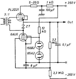
For the constant current generator, a pentode, a cascode or a transistor can be used. The switch can be constructed with an electron valve, a silicon controlled rectifier or a transistor. A practial example is shown in Fig. 4. The frequency range
Fig. 4. A regulated sweep circuit.
is 10—1200 cycles. The nonlinearity of the output sawtooth is less than 5 per cent and the amplitude variation is ± 10 per cent. The output amplitude is 190 V.
If the smoothing filter is made up from several stages, the phase shift in the feed- back loop may result in oscillations.
To illustrate the capabilities of the circuit a few figures will be quoted. Suppose a cathode follower with an input resistance of 100 Mohm is used to lessen the output loading. This also makes it possible to make Ri much smaller than R2.
At low frequencies the current from the pentode must be at least ten times the leakage current from the output loading, or the nonlinearity will be too great. If the peak-to-peak output amplitude is 200 V, the minimum pentode current will be
10 • 200/100 = 20 pA.
As the remaining error Vi is small, the ratio between the upper and lower frequency limits can now be estimated. If the pentode can deliver 25 mA, the maximum to minimum current ratio, and thus the maximum to minimum frequency ratio, is 1250.
To reduce the remaining error as much as possible, a sharp cut-off pentode should be used. With EF184 a voltage change of 3.5 V at the grid is necessary. The total amplitude change is then only 3-5 per cent of the output amplitude.
Fig. 5 shows a modification of the circuit. The positions of the switch and the constant current generator are interchanged. No extra anode-supply filtering is necessary and the biasing of the switch is simplified. A cascode gives the constant
190
o -h
250 kD Ε 88 CC
PL2D2Î 5000 npF
H F r
o -
0- 4 . 5 V
Fig. 5. R e g u l t e d s w e e p circui t w i t h a c a s c o d e c o n s t a n t curren t g e n e r a t o r .
current. When the timing capacitance is charged, its voltage rises, bringing with it the cascode grid and cathode voltages. The current is thus almost constant during any single cycle. If, however, the triggering rate increases, the output voltage and the cascode average voltage tend to decrease, while the average voltage of the grid will tend to remain the same. More current will then be drawn through the cascode, keeping the output almost constant.
The frequency range with the component values of Fig. 5 is 20—400 cycles and the amplitude variation ± 5 per cent.
-150 V -360 V -150 V Fig. 6. R e g u l a t e d M i l l e r i n t e g r a t o r .
This method of sweep and amplitude regulation can be used in any time base employing RC or RL timing circuits. The resistance is then simply exchanged for a constant current supply, regulated by the output amplitude.
As an example Fig. 6 shows a modified JVfiller integrator. V 2 is the Miller tube, its anode-grid capacitance being periodically shorted by the switch via a 150 V battery to give a suitable anode voltage at the start of the run-up sweep. V 3 acts as a clamped, inverting amplifier, feeding the regulating valve V 1, which replaces the timing resistor of a conventional Miller integrator.
As the grid of the Miller tube has nearly constant potential during the cycle, the constant current can be supplied by a triode. If ECC 83 is used, the frequency range with the components shown will be 1.5 — 15 kC/s. The output amplitude is 45 V and the variation ± 1 0 per cent.
As already pointed out, the meter indicating the anode current of V 1 can be calibrated directly in sweep frequency and sweep speed.
R E F E R E N C E S
1. D e n H a r t o g , H an d M u l l e r , F A, O s c i l l o s c o p e t i m e - b a s e circuit . Wireless Engineer 24 ( 1 9 4 7 ) 2 8 7 .
2. P u c k l e , O S, T i m e B a s e s , æ 4 3 . C h a p m a n & H a l l , L o n d o n , 1 9 5 1 .