CHAPTER 16
THEORY OF SCREW EXTRUDERS W. L Gore and James M. McKelvey
I. Introduction 589 1. Pressure Flow 592 2. Drag Flow 592 3. Velocity Distributions 595
4. Power 596 II. Flow and Power Formulas 599
1. The Flow Formula 600 2. The Power Formula 602 III. Operating Equations for Melt Extrusion 602
1. Isothermal Operation 603 2. Scale-up Rules for Isothermal Operation 606
3. Experimental Results 608 4. Adiabatic Operation 611 5. Scale-up Rules for Adiabatic Operation 6 1 6
IV. Extrusion of Non-Newtonian Melts 617
1. Flow Behavior 6 1 7 2. Power Consumption 6 2 2 V. Plasticating Extrusion 623
1. Metering Zone 627 2. Feed Zone 6 2 7 3. Transition Zone 628 4. Torpedo and Screens 629 5. Scale-up of Plasticating Extruders 629
Nomenclature 631 I. Introduction
The use of screw extruders for the fabrication of thermoplastics has in- creased enormously in the past decade. Today, extruders produce coated wire for electrical uses, plastic pipe for domestic water and for chemical plants, garden hose, packaging film, and many other products. The design and operation of extruders is something of an art and most new develop- ments have evolved by trial-and-error procedures. However, through the application of viscous flow theory, at least part of the process can be de- scribed by approximate mathematical relationships and it has been demon- strated that the extrusion theory, when combined with practical experience, is an extremely useful tool.
589
590 W . L . G O R E A N D J A M E S M . M C K E L V E Y
In the extrusion of thermoplastics the material is usually fed to the ex- truder in the form of pellets, flakes, or granules. As the screw conveys the material forward, it is heated by a combination of transferred and fric- tionally generated heat and becomes a highly viscous liquid about halfway down the screw. The action of the screw on the liquid material generates the pressure required to force it through the extruder die, which shapes the molten material into the desired form. As the material leaves the die, it is solidified by quenching with air or water. An extruder which is operated in this manner, that is, fed solid material, is called a plasticating extruder.
Extruders also find many applications in which they are used as pumps for the transportation of viscous liquids, such as lubricating oils, polymer melts, or viscous solutions of any kind. In this application the extruder is not required to melt the material and the entire length of the screw acts on a fluid. Such an extruder is called a melt extruder.
The present analysis of extruders applies only to fluids. Therefore, the analysis completely describes melt extrusion but only about half of plasti- cating extrusion. For a complete description of plasticating extrusion, studies must be made of solids transport and the energy relations at the feed end of the extruder.
The most widely used extruders, by far, are the single screw machines.
However, multiple screw extruders are also occasionally used in the plastics industry. Multiple screw extruders are of two types: those in which the screw flights intermesh; and those in which the screw flights do not inter- mesh, but do share a common housing or casing. If the leakage through the clearances is neglected, the intermeshing-flight type is a positive displace- ment pump and is not treated here. The other type operates on principles similar to the single screw machines.
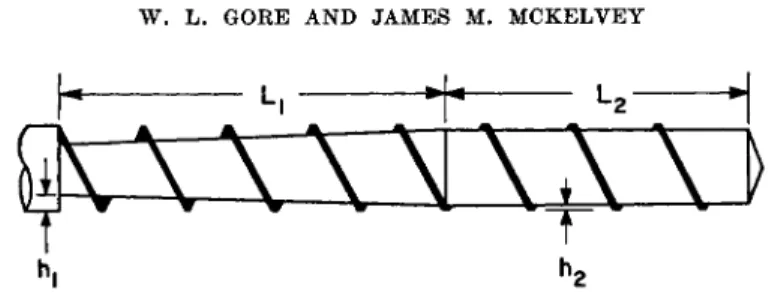
Figure 1 is a schematic diagram showing the dimensions which establish the geometry of an extruder screw. In order to make the treatment as gen- eral as possible, a multiple-flight screw having two parallel channels is
8
FIG. 1. Geometry of the multiple-flight (n = 2) extruder screw
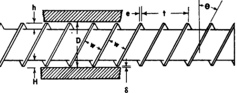
T H E O R Y O F S C R E W E X T R U D E R S 591 shown. The inside diameter of the barrel is represented by D, while h represents the distance from the root of the screw to the top of the screw flight. The radial clearance between the top of the screw flight and the barrel surface is δ. The pitch of the screw, t> is related to the helix angle by the equation
where θ is the helix angle measured at the top of the screw flight.
The width of a channel, normal to the helical axis, is w, and for a screw having η flights in parallel the following relation can be deduced :
where e is the width of the flight normal to the screw axis.
Extruders can be operated either by rotating the screw and holding the barrel stationary, or by rotating the barrel in the opposite direction and holding the screw stationary. In either case the relative motion is the same and the same operating characteristics are obtained. Since it is easier to build machines in which the screw is driven, this is the usual mode of opera- tion. However, in order to avoid having a moving coordinate system in the derivation of the extruder equations, it is assumed that the barrel is driven and the screw stationary. The equations derived for this case apply equally well to the other mode of operation.
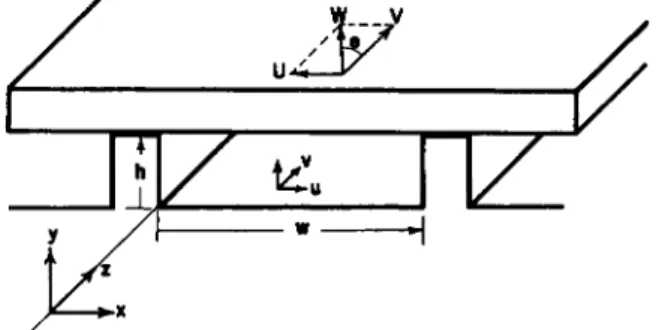
In the derivation of the extruder equations it is assumed that h is small in comparison to D. The root surface of the screw and the barrel surface can then be considered to be parallel plates and the problem is greatly simplified. This parallel plate representation is shown in Fig. 2 along with the three coordinate axes used in the derivations.
The upper plate in Fig. 2 represents the barrel. It moves over the screw channel with velocity W. The magnitude of W is πΏΝ and it is so directed that it makes the angle θ with the screw flight. In the following derivations
t = ir(D - 2δ) tan θ (1)
nw = (t — ne) cos θ (2)
FIG. 2. Parallel plate representation of an extruder screw channel
592 W . L . G O R E A N D J A M E S M . M C K E L V E Y
it is more convienent to work with the U and V components of W. As shown in Fig. 2, V acts parallel to the ζ axis and U parallel to the χ axis.
These components can be expressed in terms of the frequency of rotation by the equations
V = irDN cos Θ (3) U = wDN sin θ (4) The fluid velocity vector at any point in the screw channel is resolved into
components acting in the x, y, and ζ directions. Although a fluid particle describes a very complex motion in the screw channel, it is only the ν component, which acts in the ζ direction, that is responsible for the advance of the fluid down the screw channel. The other two components, both act- ing in a plane normal to the ζ axis, cause a circulatory motion which is important for heat transfer and mixing but contribute nothing to the pump- ing capacity of the screw. Therefore, in analyzing the pumping capacity of an extruder, it is necessary to consider only the ν component of the fluid velocity.
Along the ζ axis there are two types of flow to be considered. If there is no pressure gradient in the ζ direction, the ν component is due only to the drag effect of the barrel surface. This flow is called the drag flow. It always acts in the +z direction, when the convention is adopted that ζ increases in the direction toward the die of the extruder.
If there is a restriction at the end of the channel (for example, an extru- sion die), a positive pressure gradient will be established. This will cause some of the fluid to flow in the —z direction. This flow is called the pressure flow. It always occurs in a direction opposite to the pressure gradient.
The analysis of drag flow, pressure flow, and power in this section is based on isothermal, Newtonian flow of an incompressible fluid in a rec- tangular channel having width w and height h. It is assumed that δ is very small in comparison to h and can be neglected. It is further assumed that the flow is steady and that acceleration can be neglected. Under these con- ditions the Navier-Stokes equations1 assume a particularly simple form and solutions are readily obtained. Reference should be made to the papers of Rowell and Finlayson,2 Strub,3 and Pigott,4 for solutions similar to those presented here.
1 V. L. Streeter, "Fluid Dynamics." McGraw-Hill, New York, 1948.
2 H. S. Rowell and D . Finlayson, Engineering 114, 606 (1922); 126, 249, 385 (1928).
3 R. A. Strub, Proc. 2nd Midwestern Conf. on Fluid Mechanics,p. 481-494 Ohio täte University, Columbus, Ohio, 1952.
* W. T. Pigott, Trans. Am. Soc. Mech. Engrs. 73, 947 (1951).
THEORY OF SCREW EXTRUDERS 593
(7)
1. PRESSURE FLOW
Under the conditions mentioned above, the differential equation describ- ing the velocity distribution in the screw channel is written
(d2v/dx2) + (d2v/dy2) = (l/μ) (dP/dz) (5) where μ is the viscosity and (dP/dz) the pressure gradient.
The boundary conditions for pressure flow are υ(χβ) = 0
v(x,w) = 0 (6) K0,y) = 0
v(h,y) = 0
and a solution of (5) satisfying boundary conditions (6) is
μ\άζ/12 2
4 - ! ^
2γ (
1^
c o s h [^
2 x-
wV
2 f e] fwX]
x3 , - Î A » . \ssj cosh [jwK/2] V h J]
where Κ = (w/h). The volumetric pressure flow rate is obtained by inte- grating (7) over the cross sectional area of the screw channel.
QP = -(wh3/12μ) idP/dz) FP (8)
where
00
FP = 1 - (192/ΤΓ5Α;) Σ l/gS tanh (grK/2)
0 = 1,3,· · ·
F Ρ , which depends only on K, is the shape factor for pressure flow. Values of F Ρ for various values of Κ are plotted in Fig. 3.
2. DRAG FLOW
The differential equation for drag flow velocity is similar to (5) except that the pressure gradient along the screw channel is zero.
(d2v/dx2) + (d2v/dy2) = 0 (9) The boundary conditions for drag flow are
t,(x,0) = 0 υφ,ν) = 0
v(x,w) = V v(h,y) = 0 (10)
594
W. L. GORE AND JAMES M. MCKELVEY LO
0.9 0.8 0.7 0.6 0.8
0.4 03
0.2
(l/K)
FIG. 3. Shape factors for drag and pressure flow A solution of (9) satisfying boundary conditions (10) is
* = ( 4 7 / * )
Σ ^ ( W / » )
-1.8.·.·a/g) sinh (ÇT/K) sin (ρπχ/w)
(n)
The volumetric drag flow rate is found by integrating (11) over the cross sectional area of the channel.
QD = (wVh/2) FD (12)
where
FD = (ΙΘΚ/ττ3) Σ 1/g* tanh (gw/2K)
(7*1,3,· · ·
FD depends only on Κ and is the shape factor for drag flow. Values of FD for various values of Κ are also plotted in Fig. 3.
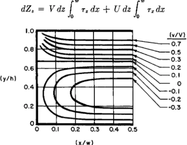
THEORY OF SCREW EXTRUDERS 595 3. VELOCITY DISTRIBUTIONS
It is interesting to examine the flow patterns within the screw channel.
The cases of open and closed discharge will be considered. When there is no pressure gradient in the channel open discharge results. The flow is pure drag flow.
Relative velocities (v/V) have been calculated with (11) for three dif- ferent values of K. Figure 4 shows lines of constant relative velocity for each K.
If the end of the channel is blocked there can be no discharge from the
0.5 0.3 0.1
( v / V ) 0.5 0.4 0.3 0.2
0.1 0.05
"0 0.1 0.2 0.3 0.4 0.5 (x/w)
FIG. 4. Lines of constant relative velocity at open discharge. Key: top, Κ = 10;
middle, Κ = 4; bottom, Κ = 1.
596 W. L. GORE AND JAMES M. MCKELVEY
screw and maximum pressure is developed. Under this condition (neglect- ing leakage) the forward drag flow is just balanced by the reverse pressure flow and
QD + Qp = 0 Substituting (8) and (12) into (13),
(dP/dz) = (βΥμ/h2) (FD/FP)
(13)
(14) By combining (14) and (7) the relative pressure flow velocities for closed discharge are obtained. The resultant closed discharge velocity is obtained by adding the drag and pressure velocities.
ν V
4
T g-
Σ
/ ΐ \ sinh (gwy/w) . , , >. FD J3y ,+ ( " ) . - £ . . 0 )
c o^ h ^ !
/ 2 t'
s i" ' ^
B}
(15)
Figure 5 shows a typical closed discharge velocity pattern.
4. POWER
Let dZs represent the power dissipated in an incremental length dz of the channel. A portion of this power causes the motion of the fluid down the screw channel, while the remainder causes the circulatory motion normal to the channel axis. Let rz be the shear stress, at the barrel surface, acting in the ζ direction and let rx be the shear stress, at the barrel surface, acting in the χ direction. The total power dissipated in the screw channel is given by the equation
dZs = Vdz f r2dx+ Udz
f
Jo
rdx
(16)(y/h)
0.2 0.3 0.4 0.5 (x/w)
FIG. 5. Lines of constant relative velocity at closed discharge
T H E O R Y OF S C R E W E X T R U D E R S 597 The shear stresses at the barrel surface are related to the shear rates at the barrel surface by Newton's law.
rz = ß(dv/dy)y=h (17)
τχ = ß(du/dy)y=h (18)
where u is the component of the fluid velocity vector that acts in the χ direction.
Combining (16), (17), and (18), the power formula becomes
, W Λ W
dZ8 = μν dz j (dv/dy)y=hdx + μϋ dz \ (du/dy)y=hdx (19) ο Jo Considering the ν component, the shear rate at the barrel surface is ob- tained by adding the drag velocity (equation 11) to the pressure velocity
(equation 7), differentiating with respect to y, and then placing y equal to h.
(5L-[(?)J...-*(f)-(?)]
l(dP\(h_4Ji y / l \ cosh [gir(2x - w)/2h]\
μ\άζ)\2 π2 ,-ίχ... \g2/ cosh [gwK/2] J
M
The first term of (19) can now be evaluated
Λ W
dZ8 = (ßV2w/h)dzFz + (wVh/2)dPFD + μϋ dz (du/dy)v=hdx (21)
Jo
where
( - D
g + 1 c o t h^ - D
s i n^ - D
(20 - 1) Κ Sm 10
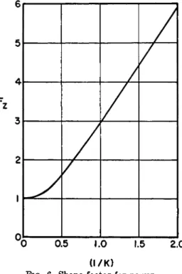
Fz is the shape factor for power and is a function of Κ only. Values of Fz , as calculated by Strub,3 are shown in Fig. 6. For values of Κ less than unity the shape factor is approximately equal to (S/K).
In the above derivation a divergent series is obtained if the integration indicated by (19) is carried out between the limits of 0 and w. The con- vergent series represented by (21) is obtained by integrating between the limits of (O.lw) and (0.9w) and then multiplying the result by (1/0.8).
The third term of (21), arising from the circulatory flow, must now be evaluated. This flow has velocity components in both the χ and y direc- tions and it would be extremely difficult to obtain a solution of the Navier- Stokes equations. An approximation is obtained by considering only the u component and neglecting acceleration. Under these conditions the dif- ferential equation for motion is
598 W . L . GORE AND JAMES M. M C K E L V E Y
6
0 0.5 1.0 1.5 2.0 ( l / K )
FIG. 6. Shape factor for power
(d2u/dy2) = (1/μ)(άΡ/άχ) (22)
The boundary conditions are
t*(0) = 0 u(h) = U (23) The solution of (22) for the boundary conditions (23) is
u = (Uy/h) + (^)(dP/dx)(y2 - hy) (24) Considering unit length of the channel, the net volumetric flow rate in the
χ direction is obtained by integrating over the depth of the channel.
ch
udy = (Uh/2) - (hz/12ß)(dP/dx) (25)
Jo
Since the flow amounts to a circulatory motion its net value is zero and the pressure gradient in the χ direction can be obtained directly from (25).
(dP/dx) = (ßUß/h2) (26)
The shear rate at the barrel surface is obtained by substituting (26) into (24), differentiating with respect to y, and then setting y equal to h.
THEORY OF SCREW EXTRUDERS
599I
h
Le cote
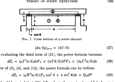
FIG. 7. Cross section of a screw channel
(du/dy)y=h = (4U/h) (27) After evaluating the third term of (21), the power formula becomes
dZ8 = (ßV2w/h)dzFz + (wVh/2)dPFD + (^U2w/h)dz (28) In view of (3), (4), and (12), the power formula can be written
It should be noted that (29) differs from the previously published power formula.5 In the previous formula the calculation of the power for the circu- latory flow was in error.6
In the preceeding section an analysis of drag flow, pressure flow, and power in a rectangular channel was made. A somewhat similar analysis is made in this section, except that it is based on a one-dimensional velocity distribution. This leads to simple expressions for flow and power which are useful for the design and analysis of many extruder screws. In addition, the restriction of zero radial clearance, which applies to the previous equations, is removed. The derivations are similar to those presented by Carley et al.7
It should be noted that the simplified flow and power equations are appli- cable only when the width-to-depth ratio of the screw channel is large, say, Κ ^ 10. Since the most efficient screw designs for thermoplastics usually have a Κ greater than 10, the formulas are useful for a wide variety of screws.
Figure 7 shows a cross section of the screw channel normal to the ζ axis.
As before, h represents the distance from the root of the screw to the top of the screw flight, w the width of the channel, and δ the radial clearance.
The distance from the root of the screw to the barrel surface is H.
8 R. S. Mallouk and J. M. McKelvey, Ind. Eng. Chem. 45, 983 (1953).
6 It has been brought to the attention of the authors that this error was discovered and the correct formula derived, independently, by R. S. Mallouk and W. D . Möhr of Ε. I. du Pont de Nemours and Company.
7 J. F. Carley, R. S. Mallouk, and J. M. McKelvey, Ind. Eng. Chem. 45, 974 (1953).
dZ8 = (ßW2w/h)(Fz cos2 (9 + 4 sin2 θ)άζ + QDdP (29)
II. Flow and Power Formulas
600 W. L. GORE AND JAMES M. MCKELVEY
1. T H E FLOW FORMULA
The differential equation for the one-dimensional velocity distribution in drag flow is obtained directly from (9).
(d2v/dy) = 0 (30)
The boundary conditions for drag flow velocity are
v(0) = 0 v(H) = V (31)
The solution of (30) for the boundary conditions (31) is
ν = (Vy)/(H) (32) In calculating the volumetric drag flow rate it is assumed that drag flow
occurs only within the actual boundaries of the screw channel (region 1 in Fig. 7).
QD = nw Γ (Vy/H) dy = n(wVH/2)(l - δ/Η)2 (33) Jo
for η channels in parallel.
By combining (2), (3), and (33) the drag flow formula can be written
QD = cxN (34)
where
a = (irDH/2){t - ne)(I - δ/Η)2 cos2 θ (35) a is called the drag flow constant. It depends only on the dimensions
of the screw and is independent of the operating conditions.
The differential equation for the one-dimensional velocity distribution in pressure flow is obtained directly from (5).
(d2v/dy2) = (1/μ)(άΡ/άζ) (36)
The boundary conditions for pressure flow velocity are
v(0) = 0 v(H) = 0 (37)
The solution of (36) satisfying boundary conditions (37) is
ν = (l/p){dP/dz){y2 - Hy) (38)
It is assumed that the pressure flow occurs in the space bounded by the root of the screw, the barrel surface, and the walls of the channel extended to the barrel surface (regions 1 and 2 in Fig. 7).
r
HQP = nw vdy = ~(nwH*/12p)(dP/dz) (39) Jo
T H E O R Y O F S C R E W E X T R U D E R S 601 By combining (2) and (39), the volumetric pressure flow formula can be written
QP = -(β/μ){άΡ/άζ) (40)
where
β = (t - ne)(Hz/12) cos θ (41)
β is called the pressure flow constant. It depends only on the dimensions of the screw and is independent of the operating conditions.
In practice, the pumping capacity of a screw will be less than the sum of the drag and pressure flow rates. This difference is attributed to the "leak- age" through the annular space between the top of the screw flight and the barrel surface (region 3 in Fig. 7).
The leakage flow interacts with the drag and pressure flows in a very com- plicated manner and an exact analysis of it has not been made. However, the leakage flow is usually a small fraction of the pressure flow, so that an approximate expression for leakage can be used with little error.
The leakage flow formula is derived by assuming that the space through which the flow occurs can be approximated by a rectangular slit having width TTD and height δ. The length of the slit depends upon the total num- ber of turns that the screw flight makes around the root of the screw and upon the width of the flight. It is given by the formula
Equivalent length of slit = (nel cos2 6/vD) (42) where I is the helical length of the screw channel.
Assuming that the dimensions of the screw are constant over the entire length, that the viscosity is constant, and that the pressure gradient is a constant, the flow rate through the slit is given by the formula
_ f W A P
W l 12GmeZcos»0) K } where
ΔΡ = Pd - Pf
Pd = pressure at die Pf = pressure at feed port
To make the form of the leakage flow formula similar to the form of the pressure flow formula, (43) is written
QL = ~(yfr){dP/dz) (44)
6 0 2 W. L. GORE AND JAMES M. MCKELVEY
where
β πΡδ ( 4 5)
1 12ne cos2 θ
To summarize, the extruder flow formula is written
Q =
QD+
QP+
QL ( 4 6 )where Q is the pumping capacity of the screw and QD , Qp , and QL are de- fined by ( 3 4 ) , ( 4 0 ) , and ( 4 4 ) , respectively.
2 . T H E POWER FORMULA
The simplified power formula is derived using ( 1 9 ) as the basis of the cal- culation. The shear rate at the barrel surface is found by adding the drag and pressure velocities (equations 3 2 and 3 8 ) , differentiating with respect to y, and then setting y equal to H.
(dv/dy)y=H = (V/H) + (Η/2μ) (dP/dz) ( 4 7 ) Substituting ( 4 7 ) into ( 1 9 ) and performing the indicated integration
dZ8 = (pW2w/H) (1 + 3 sin2 6)dz + QDdP ( 4 8 ) where the third term of ( 1 9 ) is treated in the same manner as before.
The power dissipated in the radial clearance is calculated under the as- sumption that the shear rate in the clearance is constant and equal to W/δ. The clearance power is given by the equation
dZc = [(pW2ne cos ff)/b]dz ( 4 9 ) The total power, obtained by adding the channel power to the clearance
power, is
dZ = ßW\(w/H) (1 + 3 sin2 Θ) + (ne/δ) cos Θ] + QDdP ( 5 0 ) which can be written
dZ = eßN2dz + aNdP ( 5 1 )
where
e =
T
2D
2 cos θ [(t - ne) (1 + 3 sin2Θ)/Η
+ ne/δ] ( 5 2 ) e is the power constant and is independent of all operating conditions.III. Operating Equations for Melt Extruders
In the previous section differential equations were derived which de- scribe the flow at a given position along the screw channel. To describe the
THEORY OF SCREW EXTRUDERS 6 0 3
over-all performance of an extruder, integrated equations relating output, pressure, temperature, and power to the operating conditions and the ma- chine design are needed. Approximate equations can be obtained for certain special cases, for example, when the channel dimensions vary along the screw, or when the fluid viscosity varies or does not vary along the length of the screw.
In this section some of these special cases are considered. First, the case of isothermal operation, in which the viscosity of the fluid is constant throughout the channel, is discussed. Then, the case of adiabatic operation is discussed. While it is recognized that these are somewhat idealized con- cepts, the equations have proved extremely useful as a guide in analyzing extrusion operations and in the design of extrusion equipment.
1. ISOTHERMAL OPERATION
Extruder operation is called isothermal if the fluid is maintained at con- stant temperature throughout the channel of the screw. Since the pumping efficiency of any extruder is always less than 1 0 0 % , heat must be continu- ally removed if the temperature is to be maintained constant. In practice, this is not possible or even desirable. However, in some applications the operation may be nearly isothermal, particularly when extruders are oper- ated at low speeds. For these cases of near isothermal operation the iso- thermal operating equations serve as a very useful guide.
The case where the dimensions of the screw channel are constant is con- sidered first. With a constant screw channel and isothermal operation, the pressure gradient must be constant. Consequently,
(dP/dz) = (ΔΡ/Ζ) (53) and the flow equation can be written
Q = ocN - (β + y)/(μ) ( Δ Ρ/ 0 ( 5 4 ) Equation 54 shows that a plot of Q versus ΔΡ will be a straight line having
a negative slope. This line is called a screw characteristic. For a given fluid and screw, each operating speed gives rise to a different characteristic.
The characteristics are parallel and separated by a distance that is directly proportional to the screw speed.
So far only the flow behavior of the fluid in the screw channel has been considered. The performance of the extruder as a whole, however, depends on both the flow through the screw and the flow through the die. The flow rate of Newtonian fluids through a die of any shape is directly proportional to the pressure drop and inversely proportional to the viscosity of the fluid, as shown by the equation
Q = (k/μ) (Pd - Pa) = (kfr)APD (55)
604 W . L . G O R E A N D J A M E S M . M C K E L V E Y
where k depends only on the geometry of the die and can be calculated for certain simple shapes.
The die equation shows that if the pressure drop across the die is plotted against flow rate, the result will be a straight line passing through the origin.
This line is called the die characteristic.
In most cases the pressure of the feed, PF , and the discharge pressure of the die, PA , are the same, since the feed is usually under atmospheric pres- sure and the die usually discharges to the atmosphere. In this case ΔΡ and APD are identical and the operating point of the extruder can be found by solving the die and screw equations simultaneously.
Equation 57 shows that the output of an isothermal extruder with a uni- form screw is directly proportional to the speed of rotation of the screw and is independent of the viscosity of the fluid. Equation 56 shows that the pressure developed by the machine is directly proportional to both the screw speed and the viscosity of the fluid.
The extruder operating point can also be found graphically. Figure 8 shows a plot of the characteristics of a given screw, for different operating speeds. A die characteristic is also shown. The intersection of a screw char- acteristic with the die characteristic gives the extruder operating point for that particular speed.
The total power required to operate the extruder is calculated from (51).
FIG. 8. Isothermal operating characteristics of a given screw for different speeds ΔΡ = (aßN)[(l)/(kl + ß + y)]
Q = (aN)W)/(kl + β + γ)]
(56) (57)
THEORY OF SCREW EXTRUDERS 605 Integrating (51) over the length of the screw gives
Ζ = <μΝ21 + αΝΔΡ (58)
A more general case, that in which the dimensions of the screw channel are a function of position along the screw, will now be considered. It is necessary, in the derivation, to make several simplifying assumptions. It is assumed that e is small in comparison to t and can be neglected and that δ is so small that the leakage term need not be considered. Since the pitch is related to the helix angle by the equation
t = TD tan θ (59) the flow equation can be written
Q = y2l?D2NH sin θ cos θ - (τΌΗ*/12μ) (dP/dz) sin θ (60) the net flow is constant at all positions along the screw and (60) can be in- tegrated to obtain the total rise in pressure.
Λ Ρ Γ* Λ Ρ / 1 [6*DN cos Θ 12Q Ί _
Δ Ρ = lPf d P = ί L IP— ~ ΌΪΡ^Γθ] άζ ( 6 1)
Assuming that the die discharge pressure and the feed pressure are the same, the flow rate can be determined by combining (61) and (55).
, ι
GTDN j (cos Θ/Η
2) dz
Q = - - 1 (62)
(1/Jfc) + (12/TD) ί {\/Hz sin Θ) dz Jo
Many screws are designed so that the functional relationship between Η and ζ and θ and ζ is different in different sections. For example, a screw might have a tapered section and then a section of constant root diameter.
The generalized form of (62), for a screw of m sections, is 6TDN Σ COS
Si/Hi)
dzQ ^ \ f l< (63)
(1/*) + (12/τΖ)) Σ iX/Hi sin Si) dz
i = l JO
In each section ζ is taken as a continuous variable and the Z/s are the helical lengths of the various sections.
It should be noted that with screws of variable channel dimensions, as with constant channel dimensions, the discharge rate is independent of the fluid viscosity.
A common type of screw is one in which the pitch is constant but the channel decreases in depth in a uniform manner in a rear section and then
W. L. GORE AND JAMES M. MCKELVEY
h, h2
FIG. 9. Extruder screw with compression section
remains constant in a forward section. Figure 9 is a diagram of a screw of this type. In the forward section H and 0 are both independent of z, while in the rear section Η is a linear function of z. The following formula is ob- tained by introducing these functions into (63) and then making the nec- essary integrations and summations.
The effect of using compression ratios in screws is shown by the considera- tion of an extruder in which the die opening is so large that essentially there is no backward pressure flow. In this case k is quite large and (l/k) drops out. Calculation of the delivery reveals that it is larger than that of a screw with a constant channel depth along the entire length of the screw. For example, if h equals l2 and Hi is twice H2, then the discharge rate will be 9.1 % greater than that of a screw having a constant channel depth. The increased rate is due to pressure being developed in the rear section of the screw and causing a forward pressure flow which increases the discharge rate.
2. SCALE-UP RULES FOR ISOTHERMAL OPERATION
The following scale-up rules are derived for any isothermal melt extruder and are not limited to screws of constant cross section. It is assumed that the die discharges at a pressure equal to the feed pressure. The flow equation is written
Q = [{QrDN cos B)/HMJHt + h/HA
(64) (l/k) +
[\2/(DHi
sin e)][k/H, + (k/H^H, +H
t)/2HA
Q = aN - 09 + γ) (Ι/μ) (dP/dz) (65) and it follows that
Combining the die flow equation with (66),
AP = (67)
T H E O R Y O F S C R E W E X T R U D E R S 607 Consider now a pair of extruders, one a geometrically similar model of the other. All of the dimensions of the larger are X times those of the smaller, including the die. The two extruders are operated at the same speed and pump the same fluid. Referring back to the definitions of a, 0, 7 , c, and k, the following relationships can be established.
XZ = (k2/k1) = (α,/αχ) X4 = ( f t / f t ) = (72/71)
The subscripts 1 and 2 refer to the small and large extruders, respectively.
It will now be shown that the pressure developed by the small extruder is the same as the pressure developed by the large extruder, i.e., the value of equation (67) is the same for both extruders. Consider first the numerator of equation (67). Let f(z) represent (αι)/(βι + 7i) and g(z) represent ( a2) / ( 02 + 72). Since any point ζ on the small extruder corresponds to the point Xz on the large extruder, it follows that
/(*) = Xg(Xz) (68) Considering now the numerator of equation (67),
Χ ( 1 g(Xz) dz = J 2 g(z) dz (69) Jo Jo
since
h = (k/X)
By similar arguments it can also be shown that the value of the denomina- tor of equation (67) is the same for both extruders. Therefore both machines develop the same pressure.
ΔΡι = ΔΡ2 (70)
From equation (54) it follows that
Q2 = X3Q i (71)
and from equation 65 that
(dP/dz)i = X (dP/dz)2 (72)
The relationship between the power requirements is obtained by writing equation (42) in the form
dZ = eßN2dz + aN{dP/dz)dz = v{z)dz (73) For similar extruders at corresponding points,
608 W. L. GORE AND JAMES M. MCKELVEY
v2(Xz) = X\{z) ( 7 4 )
Integrating equation (73), the relation between the total power consumption for the two extruders is found to be,
Thus, geometrically similar isothermal melt extruders should develop equal pressures, while the outputs and power consumptions will be in the ratio of the cubes of the diameters.
3. EXPERIMENTAL RESULTS
The literature of experimental extrusion studies is quite limited. The first systematic investigation of screw pumps was reported by Rowell and Finlayson2 in 1928. Their apparatus consisted of a 0.5-in. rotor with a right-hand channel starting at one end and a left-hand channel starting at the other end. The rotor fitted inside a cylindrical barrel which was open at both ends and had a discharge port at the center. The feed entered at both ends, was pumped to the center by the two screw flights, and was discharged through a valve. A variety of screws was tested in which the channel depths ranged from 0.003 to 0.062 in. On all of the screws the pitch was 0.375 in. Many experiments were carried out with a wide variety of liquids, such as water, soap solutions, petrol, and oils. The data were cor- related on the basis of flow equations which Rowell and Finlayson had previously presented in 1922. These flow equations are similar to those presented in the preceding sections of this chapter, and in all cases the data confirmed the validity of the equations.
Another report of experimental studies on screw pumps was by Pigott4 in 1951, who was primarily interested in the extrusion behavior of rubber stocks. In his paper he reviewed the theoretical flow equations and also reported some experimental work on the pumping of Newtonian fluids in a one-inch diameter extruder.
In one series of experiments, the pressures developed at closed discharge by various screws were measured. The experimentally determined pressures were found to agree with the values calculated from the flow equations for the case of closed discharge. In another series of experiments, using a fluid of approximately 1400-poise viscosity, the pressures developed at closed discharge for a given screw design, but for different radial clearances, were measured and agreed closely with calculations made with flow equations which included a leakage flow term.
In still another series of experiments, using oils of 0.5- and 1.1-poise viscosity, Pigott measured the discharge rates and pressures when extrud- ing through dies of various flow resistances. The screw characteristics
Z2 =
X3
z
x (75)T H E O R Y O F S C R E W E X T R U D E R S 609
ι* Pressure tap
« = » Thermocouple
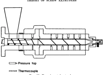
FIG. 10. Experimental extruder
plotted from these data are straight lines, as predicted by the theory. For both oils, the open discharge rate is the same. This is to be expected, as the drag flow rate is independent of viscosity. However, the slope of the screw characteristic with the more viscous oil was about twice that with the less viscous oil.
In 1953, further experiments were reported by McKelvey8 in which corn syrup was pumped with a 2-in. diameter screw. Corn syrup is essentially a Newtonian liquid. Figure 10 shows a diagram of the apparatus that was used. The barrel was provided with alternating pressure and temperature taps, so that the pressure and temperature gradients along the length of the screw could be measured. The head of the extruder accommodated interchangeable cylindrical dies and also a pressure gage and a thermo- couple which measured the pressure and temperature of the fluid just be- fore it entered the die.
Three runs were made using three different size cylindrical dies. During these runs, the pressure at the die, the output, and also the pressures along the barrel were measured.
Figure 11 shows a graph of the pressure points. Lines drawn through these points have a constant slope, which is to be expected for isothermal Newtonian flow in a channel of uniform dimensions.
In all of the runs made during these experiments, the viscosity of the corn syrup was different, owing to differences in temperature and (prob- ably) the water content of the syrup. The viscosity of the corn syrup is
8 J. M. McKelvey, Ind. Eng. Chem. 45, 978 ( 1 9 5 3 ) .
610 W . L . G O R E A N D J A M E S M . M C K E L V E Y 2 5 0
2 0 0 1 5 0 1 0 0 5 0 0
^ 2 5 0
Ίλ
2 0 0ci
— 1 5 0 3 10 0
2? 5 0
ÛL
0 2 5 0 2 0 0 150 100 5 0 0
0 2 4 6 8 10 12 14 16 18
Distance from die (inches)
FIG. 11. Pressure profiles. Key: A, 1.24 r.p.s.; B, 0.90 r.p.s.; C,0.63 r.p.s.; D,0.32r.p.s.
very sensitive to moisture content, and since the syrup was reused many times, the moisture content undoubtedly changed with time. However, the theory for this type of operation shows that the discharge rate should be independent of viscosity and depend only on the speed of rotation and the dimensions of the screw and die. Figure 12 shows a plot of the measured discharge rates, plotted as a function of the screw speed. The solid lines show the extruder flow characteristics calculated from flow equations based on the two-dimensional velocity distribution. The dashed lines show the characteristics calculated from the simplified flow equations. The experimental points are evenly distributed close to the solid lines, indicat- ing that the two-dimensional flow equations accurately describe the flow behavior of Newtonian liquids in screw extruders. The slopes of the lines calculated from the simplified flow equations are about 9% higher than those experimentally observed.
The viscosity of the corn syrup can be calculated in two ways. First, the flow rate-pressure drop data for the cylindrical dies can be used with the Poiseuille equation. In this way the Poiseuille viscosity of the corn
THEORY OF SCREW EXTRUDERS 611 0.5
0.4
a 0.3
0.2
0.1
/
/ /
/
//
^ -
Λ
0.2 0.4 0.6 0.8 1.0 1.2 1.4 Screw speed (r.p.s.)
FIG. 12. Extruder flow characteristics. Key: O , experimental;
- - , simplified theoretical.
-, theoretical;
syrup was calculated for each run. The extrusion viscosity of the fluid in the screw channel can be calculated from the pressure profile data with the extruder flow equation.
M = (0 + 7) (dP/dz) = (0 + 7) (AP/L) sin θ (76) (aN - Q) — """ (aN - Q)
where L is the axial length of the screw. The mean difference between the values is 0.0002 lb. force-sec. per square inch or about 5 % , which is well within the experimental error.
The results reported in these investigations are an experimental verifi- cation of the theoretical flow equations. So far, no precise measurements of power consumption of melt extruders have been reported.
4. ADIABATIC OPERATION
The special case in which an extruder is operated adiabatically is con- sidered in this section. The development is similar to that presented by McKelvey.9 In adiabatic operation the extruder is assumed to be perfectly insulated and the pressure and thermal energy in the extrudate is obtained only from the action of the screw on the fluid. In adiabatic operation the temperature of the fluid rises continually along the length of the screw, ac- companied by a corresponding decrease in viscosity.
For the development of the adiabatic extrusion theory it is necessary to have an analytical expression relating temperature and viscosity. It has
9 J. M. McKelvey, Ind. Eng. Chem. 46, 660 (1954).
612 W . L . G O R E A N D J A M E S M . M C K E L V E Y
long been known that viscosity-temperature data for liquids can be corre- lated, over limited ranges of temperature, by plotting the logarithm of viscosity versus the reciprocal of absolute temperature. Consequently, the viscosity-temperature relationship of liquids is usually given by an equation of the form
μ = Ae'ElRT) (77)
where Ε is the so-called energy of activation for viscous flow. However, when this equation is used in the development of the adiabatic theory, solutions can be obtained only as slowly converging series. This slow con- vergence would destroy much of the utility of the adiabatic equations.
This problem was eliminated by using the following equation to relate viscosity to temperature.
μ = ae-bT (78)
In the temperature range which is of interest for the extrusion of polymeric materials (about 100°C. to 300°C), equation (78) will correlate viscosity- temperature data just about as well as equation (77).
Consider a section of a screw of length dz. Over this length, the pressure rise is dP, the power dissipated is dZ, and the temperature rise of the material is dT. The flow rate through the section is Q. An energy balance is obtained by equating the increase in pressure and heat energy of the material as it passes through the section to the rate at which the mechani- cal energy is dissipated.
CQdT + QdP = *μΝ2αζ + aNdP (79)
In equation (79), where C is the heat capacity per unit volume, the QdP term represents the increase in pressure energy of the extrudate. In all cases, the pressure energy is much less than the heat energy term, CQdT;
calculations show that it generally amounts to less than 10%. Therefore,
*Ν*μάζ » (aN - Q)dP (80) and equation (79) becomes,
CQdT = eßN2dz (81)
It is now convenient to write the viscosity-temperature relationship (equa- tion 78) in terms of T/ and μ/, the temperature and viscosity at the inlet to the extruder.
μ = M /e x p [ - 6 ( T - T/)] (82) By substituting equation (82) into equation (81) and rearranging, a form
T H E O R Y O F S C R E W E X T R U D E R S 613 convenient for integration is obtained. Integrating between the limits of Tf and T,
Τ = Tf+ (1/6) ln (1 + MN2z/Q) (83) where
Μ = (μΜ)/((Ι)
By differentiating equation (83), the temperature gradient (dT/dz) at any point along the extruder screw is obtained.
b(dT/dz) = (MN2)/(Q + MN2z) (84)
The flow equation can be written in the following form,
(dP/dz) = μ(αΝ - Q)/(ß + y) (85)
Combining it with (81),
Substituting (84) into (86) and integrating between the limits of Pf and P,
P = ^ + [ W R | ] L N 1 +( M I V ) ( 8 7V Q >
In the previous sections the case of isothermal extrusion was considered, and an equation was derived which related the two variables, ΔΡ and Q, to the screw speed N. This equation was called a screw characteristic and, when it was combined with a die characteristic, the operating point of the extruder was fixed. In a similar manner, an adiabatic screw characteristic which relates the three variables, AT, ΔΡ, and Q to the screw speed Ν can be obtained. The adiabatic screw characteristic combined with a given die characteristic likewise fixes the adiabatic operating point of the ex- truder. The pressure developed is obtained from (87) by replacing ζ with I.
The total temperature rise over the screw is obtained from (83).
AT = (1/6) ln (1 + MN*l/Q) (89) Combining (88) and (89),
(N2AP) C
(QAT) «08 + y) (aN - Q) (90)
614 W . L . G O R E A N D J A M E S M . M C K E L V E Y
The screw characteristic can also be written in the form
(Q/N) = « - [(0 + y)e/C](NAP/QaT) (91) (91) shows that a plot of (NAP/QAT) versus (Q/N) will be a straight line
with a slope equal to [(β + y)e/C]. The intercept with the ordinate will be equal to a.
Equation (83) can be written
exp [b(Td - Τ/)] = 1 + MNH/Q (92)
and from (82)
Therefore,
exp [b(Td - Tf)\ = Uf/ud (93)
R = 1 + MNH/Q (94) where
R = ßf/i*d Introducing the die flow equation
Q = ψ/μ)ΑΡ (95) into (88),
Combining (94) and (96),
( ^ ) - ( ά ) ( - ^ ) - < » >
Rearranging (97)
( ^ ) - U ) « - « ) - ^ >
Equation (98) is the operating equation for adiabatic operation. It contains one unknown, # , and two dimensionless groups, (β + y)/(kl) and (a)/
(MNI) which are functions only of the dimensions of the extruder, the frequency of rotation of the screw, and the physical properties of the ex- trudate. Once the value of R is calculated from (98), the output, pressure, temperature, and power requirement can be determined. The output is obtained by rearranging (94).
Q = (MN%/(R - 1) (99)
THEORY OF SCREW EXTRUDERS
615The temperature rise is obtained by combining (93) and (94) and rearrang- ing.
AT = (l/b) In (1 + MNH/Q) (100) The pressure rise is obtained by combining (94) and (95).
The power requirement is obtained from the extruder energy balance.
Ζ = CQAT + QAP (102) The direct calculation of R from (98) is difficult. However, the graph
shown in Fig. 13 enables values of R to be obtained quite readily. Various values of R are plotted in Fig. 13 as functions of the two dimensionless groups, (β + y)/(kl) and (a)/(MNl). Therefore, to obtain R it is necessary only to calculate (β + y)/(kl) and (a)/(MNl) and then read the value of R from Fig. 13.
O.OI 0.02 0.04 Q08 0.20 0.40 0.80 2.0 4.0 8.0 0.06 0.10 0.60 1.0 6.0 10.0
(£+y/kl)
FIG. 13. Values of R
6 1 6 w . l . g o r e a n d j a m e s m. m c k e l v e y
and from (83),
therefore,
Referring to (88),
M2 = X2M, (108)
A2/MM = AI/MM (109)
( f t + 7t)/AA = ( f t + 7 i) / * A (110)
B2 = Αχ (111)
With reference to (99), (100), (101), and (102), the following scale-up rules are deduced.
Q2 = X3QI (112)
5. Sc a l e - t j p Ru l e s f o r Ad i a b a t i c Op e r a t i o n
Consider two adiabatic extruders, a large one and a geometrically simi- lar scale model. The scale model is so constructed that all of the dimen- sions of the large extruder, including the die, are X time larger than the corresponding dimensions of the model. The subscript 1 refers to the model and the subscript 2 to the large extruder.
X = (e2/e0 = ( A / A ) = (H2/H0 = (k/h) = ( f c / * i ) ( 1 0 3 )
and
02 = # 1
The die constants are related by the equation
k2 = X% ( 1 0 4 )
where ( 1 0 4 ) is a general relationship valid for geometrically similar dies of any shape.
Since it is specified that the operating conditions are identical and that the same material is being extruded in both the large extruder and the model,
{NM = ( W = « y c , ) = (T/t/Tfl) = ι
The relationships between the screw constants of the two machines are
a2 = X*AI (105)
(ft + 72) = Χ\ΒΙ + Ύι) (106)
ci = X2(I (107)
T H E O R Y O F S C R E W E X T R U D E R S 6 1 7
AT2 = ATX ( 1 1 3 )
ΔΡ2 = ΔΡι ( 1 1 4 )
( 1 1 5 )
z
2=
IV. Extrusion of Non-Newtonian Melts
The theoretical equations which have been presented rest on the assump- tion of Newtonian flow. Since most applications are concerned with non- Newtonians, the question arises as to how well these equations apply in practice.
Screw extruders are used for a wide variety of materials that differ greatly in their rheological characteristics. For example, screws are used for the extrusion of highly elastic materials such as rubber; for the extru- sion of viscoelastic materials such as polyethylene, which deviates consider- ably from the Newtonian viscosity law; for pumping polymer melts such as nylon, which is mildly non-Newtonian under extrusion conditions; and for metering and pumping simple Newtonian liquids.
For Newtonians the equations rest on a sound theoretical and experi- mental base. For other materials there is no exact theoretical or empirical method for predicting, quantitatively, the extrusion behavior of the mate- rial. The following discussion of non-Newtonians is primarily qualitative in nature. Elastic effects are not considered.
1. FL O W BE H A V I O R
It was previously shown that a linear screw characteristic is obtained for the isothermal extrusion of Newtonian liquids. The dashed lines in Fig. 14
FIG. 14. Screw and die characteristics. Key: , non-Newtonian; , Newtonian
Q
618 W. L. GORE AND JAMES M. MCKELVEY
show a set of these linear characteristics. The intercept of a characteristic with the ordinate represents the free discharge flow, or the rate of pure drag flow. For shallow flight screws drag flow is independent of the nature of the liquid, provided that the liquid wets both the screw and barrel sur- faces and that there is no slippage at these surfaces. This conclusion is valid only for shallow flight screws. When the difference between the root diameter of the screw and the inside diameter of the barrel becomes appre- ciable the shear stresses acting on the fluid planes are no longer equal and the apparent viscosity will vary throughout the channel.
An experimental study of non-Newtonian free discharge flow was re- ported by McKelvey,8 in which the free discharge extrusion rate of a mol- ten polymeric material (polyethylene terephthalate) was measured. This material, although non-Newtonian, is characterized by a rather sharp melting point and a mildly non-Newtonian flow behavior which is similar to molten nylon. This material was melt extruded with a 2-in. diameter, double-flight screw of constant pitch. The depth of the screw channel was 0.071 in. A complete description of the screw and of the experimental ar- rangement is given in reference 8. A series of extrusion runs was made at free discharge during which the polymer melt temperature was kept close to 270°C. Figure 15 is a plot of the free discharge flow rate versus the screw speed. The slope of the straight line drawn through the experimental points agreed exactly with that calculated from the extrusion equation. While this
0 0.1 0.2 0.3 0.4 Screw speed (r.p.s.)
FIG. 15. Free discharge flow. Key: , theoretical; O, experimental
THEORY OF SCREW EXTRUDERS 619 material is only mildly non-Newtonian, these experiments confirm that the free discharge flow is relatively insensitive to the nature of the liquid.
With a die on the end of the extruder the flow is restricted. Consequently, a pressure is generated which causes back flow along the screw channel.
Under these conditions the shear stress varies across the channel and the apparent viscosity of the fluid is different in different parts of the channel.
Since for the non-Newtonians the apparent viscosity decreases with in- creasing shear rate, it is possible to predict, qualitatively, the general shape of the screw characteristic for isothermal operation. First, consider opera- tion at constant speed but against various die resistances. As the die resistance and pressure increase, the driving force for back flow increases.
However, since the shear stresses also increase, the apparent viscosity of the fluid decreases. Consequently, the slope of the screw characteristic grows steeper instead of remaining constant as it does with Newtonians.
The solid lines in Fig. 14 show how the linear characteristics become dis- torted.
The screw speed also effects the shape of the characteristic. For New- tonians, characteristics for the same screw turning at different speeds are always parallel. For non-Newtonians this condition does not exist, because the apparent viscosity falls as the speed rises. This causes larger back flows, for the same pressure, at high speeds than at low speeds. Consequently, at high speeds the slope of the screw characteristic steepens more rapidly than at low speeds. Figure 14 shows this difference for the two screw characteris- tics.
In the design of extrusion equipment for non-Newtonians it is necessary to have an effective extrusion viscosity to use in the flow and power equa- tions. Given a pressure-flow rate point on the screw characteristic it is, of course, possible to solve the flow equation for "viscosity" and to call this the effective extrusion viscosity. However, this method suffers from the liability that if the characteristic has a large curvature, a different effective viscosity will be needed for each die pressure. In theory it would be far better to derive the flow equation anew on the basis of, say, the power law and to use two constants to describe the flow properties of the fluid. How- ever, this has not as yet been done, and in practice the method most com- monly used is to calculate an effective extrusion viscosity from measure- ments made in extruders under similar conditions.
A somewhat different approach was worked out by Pigott4 and applied to the extrusion of rubber stocks. He calculated (on the basis of Newtonian velocity distributions) the volume-weighted average shear rate for fluids in extruder screw channels at various back flows. Then from extrusion experiments and also from Mooney plastometer measurements he con- structed a graph giving apparent viscosity of rubber stocks as a function
620 W . L . G O R E A N D J A M E S M . M C K E L V E Y
of shear rate. In making extruder calculations the volume-weighted average shear rate is first calculated and then the effective viscosity is obtained from the diagram. Pigott reported some experiments in which there was good agreement between calculated and observed extruder performance.
In many practical cases of plastics extrusion the extruder is not operated with very large back flows and the curvature of the screw characteristics is quite small. This is particularly true for nylonlike materials. For example, the extrusion viscosity of polyethylene terephthalate at 270°C. was deter- mined in a series of experiments reported by McKelvey.8 Runs were made using three different multiple orifice dies and the screw characteristics were constructed from the pressure-flow rate data. Figure 16 shows the screw characteristics obtained for three screw speeds. Within the limit of experi- mental error, the slopes of the three characteristics are identical. The ex- trusion viscosity calculated from the slope of these lines is 0.0341 lb. force- sec./sq. in. (2350 poises).
On account of the commercial importance of polyethylene, considerably more attention has been devoted to its extrusion behavior than to that of many of the other plastics. However, these studies have had to be carried out with plasticating extruders, as under normal laboratory conditions it is very difficult to supply molten polyethylene to an extruder. When a material is extruded in a plasticating extruder an unknown quantity is
0.0 51 , , 1 , , ,
Ο 1 0 0 0 2 0 0 0 3 0 0 0 Pressure (p.s.i.)
FIG. 16. Screw characteristics for polyethylene terephthalate at three screw speeds. Key: A , 0.256 r.p.s.; B , 0.192 r.p.s.; C , 0.087 r.p.s.
THEORY OF SCREW EXTRUDERS 621
0 . 0 0 4
0.1 0.2 0.4 0.6 0.8 1.0 2 4 6 8 10
Polyethylene melt index
FIG. 17. Polyethylene extrusion viscosities
introduced into the extrusion-viscosity calculations, since the position in the screw where the polyethylene first becomes fluid is unknown. Therefore, with ordinary extrusion equipment -this position must be estimated and this introduces a large element of uncertainty into the viscosity calcula- tions. In addition a large amount of heat is generated by viscous shearing in polyethylene, and it is difficult to maintain isothermal conditions. This introduces another uncertainty into the calculations. These problems can be resolved to large degree if pressure measurements are made along the length of the barrel. Then, two pressure points can be selected which are so close together that the temperature error is small.
The apparatus shown in Fig. 10 has been used by the authors to study the extrusion behavior of polyethylene. Experiments have been carried out at different temperatures and with different grades of polyethylene, and effective extrusion viscosities have been calculated. Figure 17 is a diagram10 which has been constructed on the basis of these measurements.
The temperature range has been extended by applying (77) to the flow io J. M. McKelvey, SPE Journal 9(3), 12 (1953).
622 W. L. GORE AND JAMES M. MCKELVEY
data and using activation energies obtained from experiments with a piston type viscometer. The polyethylene grade is characterized by the melt index,11 which is a measure of the amount of polyethylene which will flow through a standard orifice, at a standard pressure, and at a standard tem- perature, in a given length of time. High melt indices correspond to low melt viscosities and low molecular weights.
While the viscosities obtained in this manner are approximate, they have proved useful for the design of polyethylene extruders that are intended to operate with small pressure flows and at normal screw speeds (say, 30-60 r.p.m.).
The flow through the die is a pressure flow and it is possible, for dies of simple geometry, to calculate the die characteristic for many non-New- tonians, using a power law. If the power law is written
r = B{y)m (116)
where
7 = shear rate, r = shear stress
and Β and m are constants, then for cylindrical dies the characteristic is defined by the equation
Q = {2B)-Wm\Rm+* (^Jm (117)
Equation (117) shows that a logarithmic plot of Q versus Ρ will be a straight line. This has been verified, over limited ranges of shear rate for many high polymeric substances. The die characteristic shown in Fig. 14 has the parabolic shape that is obtained by plotting on arithmetic coordinate paper.
The extruder operating points are located at the intersection of the screw and die characteristics, as shown in Fig. 14. From this, it appears that under the same operating conditions, equal flow rates can be obtained with non-Newtonians as with Newtonians, but that lower pressures will be generated at the die. However, a quantitative theory is needed before any definite conclusions can be drawn.
2. POWER CONSUMPTION
Serious error will result if the power for the extrusion of non-Newtonians is calculated with the usual power formula, because the calculated clearance power will be too large. Since the depth of the screw channel is usually 10 to 20 times that of the radial clearance, the shear rate in the clearance is
" R. E. Jolly and J. P. Tordella, Modern Plastics 31, 146 (1953).


![FIG. 8. Isothermal operating characteristics of a given screw for different speeds ΔΡ = (aßN)[(l)/(kl + ß + y)]](https://thumb-eu.123doks.com/thumbv2/9dokorg/1178941.86424/16.664.182.458.574.857/isothermal-operating-characteristics-given-screw-different-speeds-δρ.webp)