Characteristics of Thermally Sprayed NiCrBSi Coatings before and after Electromagnetic Induction Remelting Process
Petru Cristian Vălean
1,2, Norbert Kazamer
1,2,
Dragoș-Toader Pascal
2, Roxana Muntean
2, István Barányi
3, Gabriela Mărginean
2, Viorel-Aurel Șerban
11Politehnica University Timișoara, Department of Materials Science and Manufacturing Engineering, Piața Victoriei nr. 2, 300006 Timișoara, Romania viorel.serban@upt.ro
2Westphalian University of Applied Sciences, Department of Materials Science and Testing, Neidenburgerstr. 43, 45897 Gelsenkirchen, Germany
petru-cristian.valean@studmail.w-hs.de, norbert.kazamer@w-hs.de,
dragos.pascal@w-hs.de, roxana.muntean@w-hs.de, gabriela.marginean@w-hs.de
3Óbuda University, Bánki Donát Faculty of Mechanical and Safety Engineering, Népszínház u. 8, H-1081 Budapest, Hungary, baranyi.istvan@bgk.uni-obuda.hu
Abstract: Active mechanical components that work in highly aggressive environments require protection against premature deterioration and, at the same time, it is necessary to ensure a long lifespan. In order to achieve these important features, a protective coating can be added. In this work, a NiCrBSi self-fluxing alloy powder was employed, as feedstock material. The coating was deposited by means of oxyacetylene flame spraying process, achieving a thickness of approximately 1000 µm and exhibiting a high degree of porosity and a weak mechanical adhesion to the substrate. To improve these characteristics, a remelting process using high frequency currents was applied. After the remelting process, the porosity decreased, from an initial value of approximately 15%, to a final value under 3%. Although the microhardness values did not change significantly, both wear-rate and corrosion behavior improvement, after the electromagnetic remelting, was observed.
Keywords: NiCrBSi; self-fluxing alloy; flame spraying; inductive remelting process; pin- on-disk; microhardness; corrosion behavior
1 Introduction
Parts that work in highly aggressive environments must be protected against premature deterioration, corrosion and wear and at the same time, it is strongly
necessary to ensure a long lifetime of the components. Thermally sprayed coatings offer a practical and economical solution to improve corrosion and wear resistance on these types of elements [1, 2]. Nickel based hard materials, such as NiCrBSi family; have been recently used in industries where corrosion and wear resistance is strongly required like: paper, petrol, hot working punches or heat exchangers [3-6]. Many studies showed that these coatings are an alternative for hard chromium coatings, which are harmful to the environment [7].
Thermal spraying is regarded as a suitable technique of coating components, in which a molten or semi-molten material is sprayed on a surface, which is commonly degreased and sand-blasted in advance. The technology can provide coatings thicknesses from a few micrometers to a few millimeters, depending on the used material and the applied coating technique. The majority of coating techniques which belong to thermal spraying use a powder as raw material. For example, high velocity oxygen fuel (HVOF) process can be used in order to obtain reduced porosity for the as sprayed coatings [8]. Another combustion process is flame deposition, using oxyacetylene. This process is also known as LVOF (low velocity oxygen fuel), which is generally used to repair damaged parts [9].
Currently, a great deal of conventional and expensive processes are studied and employed in order to deposit NiCrBSi powder on various substrates. An attempt of HVOF deposition of NiCrBSi coatings with a high content of Cr (14.5%) and Fe (4.5%) on a low alloyed steel substrate was successfully performed by L.
Vieira et al. Though, the microscopic investigations revealed cracks at the coating- substrate interface, with possible peeling, it shower as well a high degree of micro porosity in the coating [10]. Another research in this field was performed by a team from the Netherlands, which tried to apply a coating using a similar type of powder, but with a higher Cr content (16.5%) by means of laser deposition process. The obtained NiCrBSi coating exhibited significant cracks and possessed high concentration of internal stress, although a pre-treatment of the substrate at 500°C was applied [11].
Therefore, this work aims to deposit the self-fluxing alloy NiCrBSi using a two- step deposition process. Firstly, an inexpensive deposition technique is considered (LVOF). The thermal spraying method consists of melting and propelling particles by a flame, towards a substrate, in order to form the NiCrBSi coating on a EN S355 J2 steel. Secondly, to solve the initial problems regarding the increased porosity, minimize the induced microcracks and to investigate the corrosion and wear behavior, flame remelting and high frequency current remelting was performed.
2 Experimental Procedure
2.1 Materials
The powder N330-FS6 delivered by the British company LSN Diffusion used in this study is a nickel based alloy produced through water atomizing process. The chemical composition of the powder can be seen in Table 1.
Table 1
The chemical composition of the NiCrBSi employed powder
Powder Ni [%] Cr [%] B [%] Si [%] Fe [%]
N330-FS6 bal. 6 1 1.5 0.3
Employing this technique, spherical powder particles with small internal porosities and excellent flowability are produced [12]. In Figure 1, the morphology of the NiCrBSi powder used as a raw material is presented.
The elements Cr and B, which are present in the chemical composition of the powder increase the corrosion and respective the wear resistance, due to the fact that they are carbide-forming elements. Moreover, the presence of Si and B favors the wettability and deoxidation during the remelting process [13]. Additionally, these elements decrease the rate of un-remelted particles after the deposition process and after the heat treatment [14]. As substrate material, a non-alloyed EN S355 J2 quality steel was chosen.
Figure 1
SEM micrograph of NiCrBSi gas atomized water collected powder
2.2 Sample Preparation
The NiCrBSi powder was sprayed using a LVOF technique, applying an oxidant flame, produced by a mix of gases, oxygen and acetylene. The coatings were deposited by the company Karl-Schumacher GmbH, Germany using a flame spraying gun produced by Metatherm, Germany. The geometry of the substrate was a cylindrical workpiece with a diameter of 70 mm and a length of 50 mm.
Specimen degreasing and activation before deposition was done with alcohol followed by sandblasting creating the conditions for a good mechanical hooking of the splats. The sample was fixed in a lathe machine and the deposition process was performed. The spraying gun was advanced with a constant feed rate until a thickness of approximately 1mm was achieved.
After the spraying process, the sample was subjected to two different remelting processes. The first sample was remelted by flame using an oxyacetylene gas process with a neutral stoichiometry. The second sample was remelted using an EKOHEAT 200/30 induction heater manufactured by Ambrell, The Netherlands.
The induction heating unit requires from 15 kHz to 40 kHz frequency range.
According to a similar research made by Hemmati and the team, the remelting process consisted of a preheating step [11] with a velocity of the inductor relatively four-time faster than the one used for the remelting procedure.
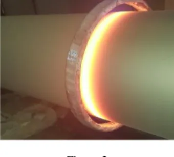
Figure 2 presents the inductive remelting process of the NiCrBSi coating. The as- sprayed specimen was inserted in a copper coil, fixed in a lathe machine, which was continuously rotated. The induction coil was moving from right to left with a constant speed.
Figure 2
Inductive remelting process of the NiCrBSi coating
For further analysis, metallographic samples were prepared according to the standard guide for metallographic preparation of thermal sprayed coatings [15].
3 Results and Discussion
3.1 Morphology and Porosity of the NiCrBSi Coating
In the case of as-sprayed NiCrBSi coating presented in Figure 3, it can be remarked a network of interconnected porosity and unbound particles due to the impact, rebound and contraction of the particles, with the substrate during the deposition process. Nonetheless, taking into account the technological advances, the flame-sprayed NiCrBSi coatings contain unwanted oxides, show moderate adhesion to the substrate and contain a large amount of porosity [16].
Figure 3
SEM micrograph of the as-sprayed NiCrBSi coating
The porosity degree was calculated with the aid of Leica QWin Image Processing and Analysis Software. The micrographs were acquired with an optical microscope and further processed. Figure 4 exhibits a considerably decrease of porosity from 15% in the case of as-sprayed coatings to a mean value of 1% after the flame remelting and respectively 0.5% after electromagnetic remelting treatment. The decrease of porosity in the case of the electromagnetic post- treatment can be caused by the capacity of the installation to control and set the temperature at a point close to the eutectic one where the wetting of the surface is done realizing a good gas extraction and a void closure.
Figure 4
Optical micrographs of as-sprayed (a), flame remelted (b) and inductive remelted coatings (c)
a b c
15% 1% 0.5%
a
The significant decrease of the porosity degree observed after the remelting process provides important information regarding the effectiveness of the post treatment, obtaining in this way a more compact NiCrBSi coating with a better adhesion to the substrate.
3.2 Microhardness and Tribological Behavior of the NiCrBSi Coating
Microhardness investigations were carried out on a Zwick Microhardness tester according to ISO 6507. The microhardness measurements were performed in 9 different spots along the cross-section of the NiCrBSi coating, the load used for determining the Vickers microhardness was 3 N applied for 15 seconds on each indentation and the distance between measurements was 0.15 mm. Figure 5 presents the values for the Vickers microhardness obtained for the NiCrBSi coating remelted by flame and respectively remelted using electromagnetic induction.
Figure 5
Microhardness values obtained for flame and electromagnetic remelted NiCrBSi coatings A mean value of 390 HV0.3 was obtained for the flame remelted samples. For the electromagnetic fused samples 430 HV0.3 was measured with a smaller standard deviation, showing a homogenous coating along the surface. It is generally known that the hardness respectively the nanostructure of a material will directly influence its wear behavior [17]. Therefore, the sliding wear tests were performed using a pin-on-disc arrangement (POD) compliant to ASTM G99 and DIN 50324.
This test design was chosen as the device is equipped with a friction coefficient transducer, providing on-line measurement of the friction coefficient. Testing parameters were maintained constant for all the samples: a counterbody of WC- Co, 6 mm diameter, 10 N load, linear speed of 15 cm s-1 and 15000 laps (566 m).
Electromagnetic remelting
Flame remelting
Prior to the POD tests, all of the specimens were ground to a plane surface having the same roughness, cleaned with acetone and dried under warm air. The friction coefficient was continuously monitored during the tests. In this regard, the measured coefficients of the WC-Co ball against the coatings are presented in Figure 6.
For NiCrBSi coatings remelted by induction, the friction coefficient had a mean value of 0.603. Tribological tests concluded that the friction coefficient had a stable behavior, without fluctuations for the first 10000 laps and after that, it increased from 0.5 to 0.64 and stabilized at this value. The measurements showed that the NiCrBSi coating remelted by induction process exhibits a lower and steadier coefficient of friction in comparison with the flame remelted coating. The lower value of the friction coefficient obtained for the samples remelted by induction process, may be attributed to the lower porosity and a better adhesion between the particles of those samples, which leads to lower friction forces at the contact between sample and counterbody.
Figure 6
Friction coefficient of flame remelted and inductive remelted NiCrBSi coatings
After the test, the wear track investigations were performed on a confocal laser microscope, which facilitated the measurement of the depth of the tracks. The wear profiles of the NiCrBSi coating together with the mapping of the wear track are illustrated in Figure 7 and Figure 8.
Figure 7
Wear track for sample remelted by flame
Figure 8
Wear track for sample remelted by inductive process
The wear rate calculated for induction remelted samples was 1.178·10-4mm3N-1m-1 respectively 2.338·10-4 mm3 N-1 m-1 for the flame remelted ones. The obtained results demonstrate that a higher hardness of the tested surfaces leads in this situation to a lower material removal from the coating, giving a better resistance to wear in the case of induction remelted samples. In the previous figures one may observe that penetration depth of the ball was much lower for the inductively remelted coating (7.5 μm for the inductive remelted coating respectively 17.3 μm for the flame fused coating).
3.3 Adhesive Properties
The adhesion to the substrate is one of the most important properties of the coated components. In order to determine if the coating has a good adhesion to the
substrate, the samples were investigated by realizing indentations on the substrate- coating interface.
The indentations were performed in different spots of the cross-section along the interface between the NiCrBSi coating and the substrate. The load used for examining the adhesion was 1200 N applied for 15 seconds on each test. In Fig. 9, before the remelting process, delamination, low mechanical bonding and cracks can be observed at the interface and in the coating. Figure 10 illustrates the indentations on both samples.
Figure 9
As-sprayed coating and interface overview
Figure 10
HV 120 indentation for flame (a) and inductive remelted coating (b)
The results show that both remelting processes offered a good adhesion to the substrate and delamination did not occur.
3.4 Corrosion Behavior
The corrosion behavior of the NiCrBSi coatings was investigated by electrochemical polarization in a three electrode cell in 3.5% NaCl aqueous solution. A saturated calomel electrode (SCE) was used as reference electrode, a
b a
platinum electrode as auxiliary electrode and the NiCrBSi samples represented the working electrode. The samples were polarized in a potential interval from - 500 mV to +500 mV, with a scan rate of 0.16 mVs-1.
Table 2
Corrosion potential and corrosion current densities of NiCrBSi coatings Sample ECorr vs SCE
(i=0) [mV]
iCorr
[mA cm-2]
Flame -268 91 10-4
Inductive -217 27 10-4
Figure 11
Polarization curves of the flame respectively inductively fused NiCrBSi coatings tested in 3.5% NaCl aqueous solution
It is important to mention that Bergant et al. have demonstrated in previous studies that the Ni-based treated coatings exhibit a better corrosion resistance with a factor of 10 compared to the substrate and the as-sprayed one [18]. Considering this data, the analyzed samples were the post-treated ones. The results presented in Table 2 and the polarization curves illustrated in Figure 11 reveal a higher corrosion rate for the NiCrBSi coating remelted by flame process compared to the inductive remelted one. As can be noticed, the corrosion current density icorr is three times lower in the case of the inductive remelted sample (~27 10-4 mA cm-2) compare to the flame remelted one (~91 10-4 mA cm-2). The corrosion potential Ecorr of the inductive post-treated sample which is slightly shifted to a positive value than the flame is another sign of superiority of the red marked coating.
Regarding the anodic region of the graph, one can see that the curves present a similar behavior, presenting a slight repassivation plateau with an overlapping point at about 50 mV.
4 Conclusions
This work presents a new approach for obtaining NiCrBSi coatings with low porosity and good adhesion to substrate, using a two-step deposition process. As- sprayed, NiCrBSi coatings present high porosity, low cohesion between particles and poor adhesion to the substrate, as well as irregular surface geometry. The coatings which were remelted by induction are more compact and the porosity decreased with a factor of 30, from the as-sprayed one to the induction treated ones.
The microhardness investigations revealed that the inductive remelted NiCrBSi coatings do not present fluctuation of hardness and the mean value is 10% higher than the flame remelted ones. This fact can be attributed to a more compact microstructure with lower porosity, and a finer distribution of the phases.
Regarding the wear behavior, the wear rate of the electromagnetic samples was more than two times lower than the flame remelted one. The electrochemical corrosion tests showed that inductive remelted specimen, which is treated with a method that allows a precise control of the temperature and energy and exhibits a 3X better corrosion resistance than the flame remelted samples.
References
[1] J. Davies, Handbook of Thermal Spray Technology, Materials Park, OH, USA: ASM International, 2004
[2] P. Mrva and D. Kottfer, “Influence of Thermal Spray Coatings on the Thermal Endurance of Magnesium Alloy ML-5”, Acta Polytechnica Hungarica, Vol. 6, No. 2, pp. 71-75, 2009
[3] I. Hemmmati, R. Huizenga, V. Ocelik and J. D. Hosson, “Microstructural design of hardfacing Ni-Cr-B-Si-C alloys”, Acta Materialia, Vol. 61, No. 16, pp. 6061-6070, 2013
[4] S, Houdkova, M. Vostrak, M. Hruska, et al. “Comparison of NiCrBSi coatings, HVOF sprayed, re-melted by flame and by high-power laser”, Proceedings of the 22nd International Conference on Metallurgy and Materials, May 15th -17th, Brno, Czech Republic, 2013
[5] F. Battez, J. L. Viesca, R. Gonzales, et al. “Friction reduction properties of a CuO nanolubricant used as a lubricant for a NiCrBSi coating”, Wear, Vol.
268, pp. 325-328, 2010
[6] M. C. Lin, L. S. Chang, H. C. Lin, et al. “A study of high-speed slurry errosion of NiCrBSi thermal-sprayed coating”, Surface & Coatings Technology, Vol. 201, pp. 3193-3198, 2006
[7] S. Houdkova, F. Zahalka, M. Kasparova and L. Berger, “Comparative study
of thermally sprayed coatings under different types of wear conditions for hard chromium replacement”, Tribology Letters, Vol. 43, pp. 139-154, 2011 [8] N. Kazamer, D. Pascal, V. Serban and G. Marginean, “A comparison
between hardness, corrosion and wear performance of APS sprayed WC- CoMo and WC-Co coatings”, Solid State Phenomena, Vol. 254, pp. 71-76, 2016
[9] B. Zoran, T. Uros and G. Janez, “Effect of high-temperature furnance treatment on the microstructure and corosion behavior of NiCrBSi flame- sprayed coatings”, Corrosion Science, Vol. 88, pp. 372-386, 2014
[10] L. Vieira, H. Voorwald and M. Cioffi, “Fatigue Performance Of AISI 4340 Steel Ni-Cr-B-Si-Fe HVOF Thermal Spray Coated”, Procedia Engineering, Vol. 114, pp. 606-612, 2015
[11] H. I. V. Ocelik and J. D. Hosson, “Effects of the alloy composition on phase constitution and properties of laser deposition Ni-Cr-B-Si coatings”, Physics Procedia, Vol. 41, pp. 302-311, 2013
[12] L. Pawlowski, “The Science and Engineering of Thermal Spray Coatings”, 2nd edition, Wiley, 2008
[13] ASM International, Aloy Phase Diagram, Vol. 3, ASM Handbook, 2005 [14] Z. Bergant, J. Grum, “Quality improvement of flamesprayed, heat treated and
remelted NiCrBSi coatings”, Journal of Thermal Spray Technology, Vol. 18, pp. 380-391, 2009
[15] Standard Guide for Meallographic Preparation of Thermal Sprayed Coatings, ASTM Standard E1920-03, West Conshohocken, PA: ASM International, 2003
[16] Bergant Z. and Grum J., “Porosity evaluation of flame-sprayed and heat- treated nickel-based coatings using image analysis”, Image Analysis &
Stereologz, Vol. 30(1), pp. 53-62. 2011
[17] I. Konyashin, B. Ries, D. Hlawatschek, Y. Zhuk, A. Mazilkin, B. Straumal, F. Dorn and D. Park, “Wear-resistance and hardness: Are they directly related for nanostructured hard materials?”, International Journal of Refractory Metals and Hard Materials, Vol. 49, pp. 203-211, 2015
[18] Z. Bergant, U. Trdan and J. Grum., “Effect of high-temperature furnace treatment on the microstructure and corrosion behaviour of NiCrBSi flame- sprayed coating”, Corrosion Science, Vol. 88, pp. 372-386, 2014