Building of a mathematics-based RFID localization framework ∗
Zoltán Ruzsa
b, Zsolt Parisek
b, Roland Király
aTibor Tómács
a, Tamás Szakács
a, Henrik Hajagos
aaEszterházy Károly College, Institute of Mathematics and Informatics kiraly.roland@ektf.hu,tomacs@ektf.hu,szakacstam@gmail.com,
hajagos.henrik@gmail.com
bBay Zoltán Nonprofit Ltd. for Applied Research ruzsaz@gmail.com,parisek@gmail.com
Submitted September 4, 2014 — Accepted March 5, 2015
Abstract
In this article, we examine problems related to RFID systems in which the antennas and the connected readers are able to find a transponder with greater precision and are able to locate their position with a greater proba- bility.
The central problem is how to cover a relatively large area, such as an air- port terminal or a railway station’s waiting room, with the smallest possible number of RFID antennas.
The second important question of the research is what infrastructure and mathematical apparatus are required to decide the location of the transpon- der within an area under question, with the highest possibility.
1. RFID based localization and the problems of the presence sensors
Firstly, as part of localization problems and the possibilities of expanding percep- tion, let us define what we can see with a perception sensor and what we mean by
∗Their RFID research project was supported by the European Union and the State of Hungary, co-financed by the European Social Fund in the framework of TÁMOP-4.2.2.C-11/1/KONV-2012- 0014.
http://ami.ektf.hu
165
an RFID based perception-sensor. This is important, because both the localization problem and the mathematical model are based on the examination of perception.
An RFID Presence sensor is a device capable of detecting the presence of a spe- cific object and relaying this presence as binary information (whether it is present or not).
There are countless applications for sensors and sensor networks based on WIFI, RFID and NFC technologies in real life. Producing information regarding the position and motion of the perceived object by means of connected perception sensors (sensor network) has been the topic of a number of researchers [4, 5, 6, 7].
Several researches [8] also utilize the strength of the perceived signal to better determine the position of the object or a person. A good example of the situation underlined above is an office building where each door requires verification by an entrance card for passing.
The entrance card is, in reality, an RFID transponder, while the doors are outfitted with RFID readers.
These readers, along with their connected antennas measure whether the trans- ponder is in their range of perception or not at preset time intervals. If the transponder is far away, the outcome is most likely negative, but positive read- ing are not always guaranteed even when the transponder is closer. However, the possibility of positive feedback is higher than in the previous case.
In case somebody is standing between the transponder and the antenna, his body water blocks the spread of the signal, resulting in a negative reading. Another possibility is that the RFID tag is situated on the periphery of the reception range.
In this case, the outcome of the reading depends on other uncertainty figures such as humidity, temperature, etc.
Perception-based localization complicates the problem even further, as the cur- rently used systems are not suited to handle this task.
The fact is that transponder localization is uncertain on a smaller area and the problems mentioned before soon make the use of current RFID based devices problematic.
We can safely conclude then with using only perception sensors and RFID based systems, it is relatively difficult to accurately decide the position of an object. How- ever, we can see possibilities of expanding the perception capabilities of mentioned devices (RFID reader, antenna, antennas networks) with the implementation of intelligent algorithms and mathematics based computational models what these algorithms are based upon.
Problem(Extending of the RFID based localization). One of the central problems of our research is how to cover a relatively large area, such as an airport terminal or a railway station’s waiting room, with the smallest possible number of RFID antennas, and to estimate the exact location of as many objects tagged with RFID tags as possible with the greatest likelihood. We would also like to find a solution to expand the perception process to permanently or temporarily uncovered areas also by upgrading current RFID technologies.
As a part of the solution for the problem described above, we present the math- ematical model used to expand the perception capabilities of the localization pro- cess along with the functioning of the software background, that is, the framework which provides estimations regarding the whereabouts of the transponders using the mathematics based subsystem.
2. Planning the measurement process and calibrat- ing the test environment
In order to create and produce the mathematical model, and to prepare the con- trolling algorithms for the new antenna, we need to measure the characteristics of the antennas used in our test environment and the coverage of the test area by RFID readers.For the calibration of antennas and readers, we took measurements of the signal strength RSSI perceivable by the antennas within the discrete areas covered by each antenna, first by an accuracy of 50, then by 25 centimeters. Tak- ing constructive and destructive interference into account, we created the map of coverage.
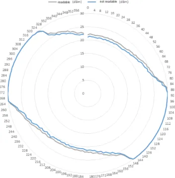
We have used similar measurements to determine the perception characteristics of the transponders what we used for localization (see in Figure 1).
Figure 1: Characteristic of the rotated UHF transponder
Parallel to these, to construct a mathematical model, we rotated the transpon- der in a given position under the same conditions. For about 1000 times/position, we measured how many times the transponder was visible (sufficiently perceiv- able) to the reader connected to the antenna. Comparing the results to the RSSI values measured before proved that the reading ratio of the antennas influenced perception frequency. It is also clear that specific space segments show relatively unique values depending on reading frequency. We excluded the possibility of any obstruction between the antenna and the reader (for example: aqueous medium or the passing of a metal-based object).
It was under these circumstances that we had to design the mathematical ap- paratus responsible for predicting where a transponder (outside of visibility range) is located inside a known but yet uncovered area.
Provided that the mathematical model is working as intended, and that the system is able to estimate the most probable position of the tag, this extra infor- mation can be used to decide the real position of the transponder (in order to make the search attempts more efficient).
3. The mathematical foundations of the extension of localization
Let (Ω,F, P)be a probability space where Ωis the set of factors that define the location of the tag or rather the outcome of the detection attempts made by an- tennas.
The Borel-measurable space part in which the tag should be located is denoted by H ⊂ Rk and let H1, H2, . . . , Hm be partitions of the Borel-measurable sets.
These Hi sets are undivided sectors in which the presence of the tag should be detected. In practiceH ⊂R2is a rectangle, sets ofHi are the cells of a grid.
Letθt: Ω→H denote a probability variable the position of an object at time momentt.
LetXit: Ω→ {0,1}probability variable (i= 1, . . . , n,t≥0) be1, if the antenna idetects the tag at timetbe0if it does not. Assume, thatX1tiX2t2, . . . , Xntn are independent of each other in case of arbitrary valuest1, . . . , tn. Let
p(i, j,1) =P(Xit= 1|θt∈Hj) and p(i, j,0) = 1−p(i, j,1),
where i= 1,2, . . . , n,j = 1,2, . . . , m andt≥0. Assume that p(i, j,1)is indepen- dent fromt, therefore the probability of antennaidetecting the tag isp(i, j,1)if it is located in the space partj, and it isp(i, j,0)if it does not. These values are not known, so in practicep(i, j,1)is replaced byp(i, j,ˆ 1), the relative frequency of the event {Xit= 1} assuming thatθt∈Hj. Likewisep(i, j,0)is replaced byp(i, j,ˆ 0).
3.1. The case of simultaneous measurements
The most manageable, but unrealistic case is when all the antennas try to detect the tag at a time instant t =t0. Let x1, x2, . . . , xn be the measurement results.
Similar to the principle of maximum likelihood estimates, as the current estimated place of the object the sector Hj is accepted in which the achieved x1, x2, . . . , xn
measurements are the most likely to occur. Therefore the maximum point of the function
P(X1t0 =x1, X2t0 =x2, . . . , Xnt0=xn|θt0 ∈Hj) in j is required to be found. Due to the independence
P(X1t0 =x1, X2t0=x2, . . . , Xnt0 =xn|θt0 ∈Hj) = Yn i=1
p(i, j, xi).
Here thep(i, j, xi)values are not known, instead theirp(i, j, xˆ i)estimation will be used. Thus, if the
Yn i=1
ˆ p(i, j, xi)
function has only one maximum point, j0, then set Hj0 will be accepted as the estimated position of the object. (If the maximum value of the function is taken of the arguments of j1, j2, . . . , jz, then the estimation will be the union of the corresponding sets Hj1, . . . , Hjz.)
3.2. The case of separate measurements made at various times
Take some measurements by sensoriat time momentsti1, ti2, . . . , tiki close to time t0.
As a result, the measured value recordedXiti1, Xiti2, . . . , Xitiki probability vari- ables can not be considered independent therefore the results of the measurements by the antennas must be aggregated. Denote the results withxiti1, xiti2, . . . , xitiki.
Assume that, there exists aK:R→R+ function, what P
ki
\
l=1
{Xitil=xitil} θt0 ∈Hj
!
= Pki
l=1K(t0−til)p(i, j, xitil) Pki
l=1K(t0−til) . Due to the independence
P
\n i=1
ki
\
l=1
{Xitil=xitil} θt0 ∈Hj
!
= Yn i=1
Pki
l=1K(t0−til)p(i, j, xitil) Pki
l=1K(t0−til) . Again, similar to the principle of maximum likelihood estimation the sector ofHj
is accepted as the estimation of the location of the object at time t0 where in case of being there the probability value of the test results is maximal. Therefore if the previously obtained
Yn i=1
Pki
l=1K(t0−til)p(i, j, xitil) Pki
l=1K(t0−til)
function has its maximum value inj at j0, the sectorHj0 will be accepted as the estimation of the object’s location. (If the function has its maximum atj1, j2, . . . jz
simultaneously at the same time, similarly to the previous cases the estimation of the object’s location will be the union of setsHj1, . . . Hjz).
In practical terms, the existence of an unification kernel K that can unify the measurements made by the same antenna at close time instants cannot be proven.
What is even more unpleasant, K function above cannot even be determined by measurements. The rightness of core function of
K(t) =
1− τt
22
if|t|< τ ,
0, otherwise,
used in the implementation can be supported only when using the calculated po- sition proves to be sufficiently accurate. (The variable τ ≥ 0 appearing in the function is used to adjust the time interval from which measurements are used to determine the position of the object. This value is defined during the process of fine-tuning. In practical testsτ= 6 was used.)
3.3. Probability of being in a given sector
Now we are looking for the answer to with what probability the tag was at time t0in a designatedHj sector. Assume that the tag could be in any sector with the same probability before the measurement, namely
P(θt∈Hj) =P(θt∈Hr) ∀j, r= 1, . . . , m.
The probability of
P θt0∈Hj
\n i=1
ki
\
l=1
{Xitil=xitil}
!
should be determined. Based on the Bayes’ theorem, this equals:
PTn i=1
Tki
l=1{Xitil=xitil} θt0 ∈Hj
P(θt0 ∈Hj) Pm
r=1PTn i=1
Tki
l=1{Xitil=xitil} θt0 ∈Hr
P(θt0∈Hr) =
= Qn
i=1 Pki
l=1K(t0−til)p(i,j,xitil) Pki
l=1K(t0−til)
Pm r=1
Qn i=1
Pki
l=1K(t0−til)p(i,r,xitil) Pki
l=1K(t0−til)
≈ Qn
i=1 Pki
l=1K(t0−til) ˆp(i,j,xitil) Pki
l=1K(t0−til)
Pm r=1
Qn i=1
Pki
l=1K(t0−til) ˆp(i,r,xitil) Pki
l=1K(t0−til)
.
3.4. The implementation
For testing a virtual test environment has been created. The basic set in which the localization of the tag was carried out was considered a square divided into10×10 grid. These squares in the grid become the setsHj.
For the sake of simplicity the elementary grid squares are indexed by{0,1, . . . ,9}
×{0,1, . . . ,9} as their coordinates. Three virtual antennas were created, A1, A2, A3, and probabilities p(1, j,1), p(2, j,1), p(3, j,1) were defined being associated with their corresponding antennas (j∈ {0,1, . . . ,9} × {0,1, . . . ,9}). Figure 2 illus- trates this.
Figure 2: The detection probability of antennasA1, A2, A3. The probability is1in the black squares and0in the white ones
3 testroutes are generated that represent the roaming of the tag (see Figure 3).
All 3 testroutes take 30 seconds and considering that the 3 antennas try to read the tag in every second, so t∈ {0,1, . . . ,29}.
Figure 3: The three virtual test routes (test tracks). The notches indicate the position of the tag in integer minutes
After each detection attempt when the antennaAi tried to read the tag at time t the position (xt, yt) of the tag during the route at time t was checked against the associated probability of p(i,(xt, yt),1) and a randompnumber with uniform distribution has been chosen from the interval of[0,1]and the
xit=
(1, ifp < p(i,(xt, yt),1), 0, otherwise,
virtual series of measurement has been created. The reading results of the antennas
during the traversal path were simulated this way. For the resulting sets of mea- surements xit (i ∈ {1,2,3}, t ∈ {0,1, . . . ,29})the positioning algorithm outlined above was performed, and the estimated( ˆxt,yˆt)coordinates by the algorithm were checked how accurately they approach the tag’s exact coordinates of(xt, yt).
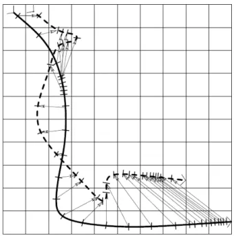
Figure 4: The route1(continuous curve) and a characteristics es- timation (dotted line). Actual and estimated position in the same time moments are connected by arrows. Squared error for the esti-
mate is5.8
To quantify the results the squared error of the route estimate
1 30
X29 t=0
(xt−xˆt)2+ (yt−yˆt)2
has been calculated. The method above was repeated 1000 times and the average of the square errors was recorded. The considered values during the route can be seen in the Table 1. As a reference the squared errors of the random guess (uni- form distribution independently considered(xt, yt) coordinates) and the constant estimation(5,5) were also determined.
The results show that the algorithm works best when the path is close to the antennas and the movement of the tag is slow (Route 1) while the detection is less accurate when the the tag is roaming in the middle of the area covered by the antennas (Route 2). Not surprisingly, the estimate of constant (5,5) provides a lesser error in this case.
route 1 route 2 route 3 squared error of algorithm 6.953 15.707 10.732 squared error of random estimate 38.947 27.893 32.351 squared error of constant estimate(5,5) 21.500 12.500 17.900
Table 1: Squared errors of the three route estimates
3.5. The localization framework
We have two large expectations, regarding the localization framework: One being for it to be able to provide an interface for the middlewares, that control the antennas, on which they can relay their detections to the system. It is expected to be able to store the information, gathered using this method, permanently.
The other being, that the system should be able to calculate the coordinates of the transponder (or maybe even a moving reader in the future), that is fixed in the system. These calculations are based on the previously stored detections.
As a solution for the aforementioned expectations, we have implemented a web- service, coded in Java programming language. Designing and implementing of the webservice was done while abiding the policies of REST (Representational State Transfer) [10]. We have chosen JBoss (Jboss AS 7.1.0.Final) [11] as our service’s application-server, for it is strongly supported by REST. For the forming of the interfaces, we employed the javax.ws.rs [12] (High-level interfaces and annotations used to create RESTful service resources) package, introduced by Java EE 6, mak- ing the usage of all these independent from language and platform. This property is nearly indispensable for a system capable of integrating heterogeneous hardware, like this one.
We can upload a detection to the framework, by employing a simple HTTP- POST [13] method, assuming that the detection we would like to upload is written in a specified XML structure. The first step of processing an uploaded detection is the serialisation of the given xml, which will result in the creation of a Detection objectitem. The Detection class indicates between which transponder and reader did the detection occur, and optionally, through which RSSI value did the commu- nication between the two happening. Among the Detection items exists a special item, which represents negative detection. The middlewares present a negative de- tection when the reader attempts to locate the transponders in their environment, but no answer is given to it.
The permanent storing of the Detection items is done inside a database, in our case, this is a PostgreSQL 9.3 [14] released database-item. Communication between the database and the server application is accomplished by the help of an ORM (Object/Relational Mapping) [15] tool, which makes our job a lot more easier, during the upgrading of the framework. Our choice for an ORM tool fell upon Hibernate (Hibernate ORM 4.3.1. Final Release), for the reason that JBoss AS 7 provides native support in case of using Hibernate ORM.
Further expectations of the localization framework include, for it to be able
to make calculations using different localization algorithms, simultaneously. This property of the system allows the upgrading of the localization algorithms to be quick and simple, in parallel with different project team’s different expectation systems, if need be.
3.6. The software component from client side
The task of the client side control is to communicate with the RFID reader then transmit the acquired data to the server. To incorporate the functions of the reader, we have developed an interface, that is able to convert the parameterized function calls into XML structures that are compatible with the reader, deliver them, and transform the given answer into a serviceable form, then return it to the location at which the call was made.
Communication with the server is also done by an interface, that is similar to the one before, having the task of converting the given data into an XML structure that is compatible with the server then processing the answer returned to it by the server.
Along with keeping up the connection with the server, the client also serves as a controlling role a controlling function, for it is able to work with more than one antenna, that are connected to the reading mechanism, simultaneously, while also having the ability to clearly identify them too. This way, we can transmit information regarding from which antenna the data came from. On top of all this, (with the help of this), we can also monitor the “GPIO status” of the nodding antennas (what kind of status was the given antenna in last time), because the dif- ferent statuses are handled with different kinds of antenna identifications. (In order to conduct indoor localization, we are using a certain type of intelligent antenna, which can change the antenna characteristics, by determining the current status of the transponders and using three integrated patch antennas. The antenna is able to locate the transponders in a given location, by turning into the appropriate direction (without mechanical movement).
The client decides exactly which reader, and which antenna should read with what kind of specifications, while during runtime by switching between these, it also governs the scanning of the given location. If necessary, it is able to modify the signal strength of the reading, the reading modes, and controls the GPIO ports of the antennas.
4. Conclusion
We can solve a lot of problems that affect or inhibit the use of RFID by extending the software in this direction and by the application of mathematical estimate, and we can give proper answer to the problem, what has been presented previously in this article.
In our opinion the system constructed by us can be used to the extension of localization processes based on RFID, and we can achieve a goal presented in the
introduction, so we can cover quite large areas by using a smaller amount of readers, and this way we can use much less resources and smaller expenses.
With the help of the above stated model we can estimate the position of those transponders that are temporarily uncovered, but they are known to be positioned within the examined area. The implemented version can decide where most proba- bly the object to be localized is, among the temporarily or permanently uncovered discreet areas.
The arguments and the implemented algorithms presented by us help the de- velopment and realization of the IOT (Internet of Things) conception since we will be able to identify the devices and their positions as well as the routes that they have covered.
References
[1] Bánlaki, J., Hoffmann, M., Juhász, T., UHF RFID tags with user interface – the ability of individual control and a new source of information,RFID Journal, 2014.
[2] Intelliflex On-Demand Data Visibilty – Intelliflex Readers,http://www.
intelleflex.com/Products.asp
[3] IntermecBy Honeywell,http://www.intermec.com/
[4] Qiang Le and Lance M Kaplan., Design of operation parameters to resolve two targets using proximity sensors. In Information Fusion (FUSION), 2010 13th Conference on, pages 1–8. IEEE, 2010.
[5] Qiang Le and Lance M Kaplan., Target localization using proximity binary sensors.In Aerospace Conference, 2010 IEEE, pages 1–8. IEEE, 2010.8
[6] J Miguez and A Artes-Rodriguez., Monte carlo algorithms for tracking a ma- neuvering target using a network of mobile sensors. In Computational Advances in Multi-Sensor Adaptive Processing, 2005 1st IEEE International Workshop on, pages 89–92. IEEE, 2005.
[7] Ruixin Niu and P Varshney., Target location estimation in wireless sensor net- works using binary data.In Proceedings of the 38th Annual Conference on Informa- tion Sciences and Systems, Princeton, NJ, 2004.
[8] Ruşen Öktem and Elif Aydin., An rfid based indoor tracking method for navi- gating visually impaired people.Turk J Elec Eng and Comp Sci, 18(2),2010.
[9] Mahesh Vemula, Joaquín Miguez and Antonio Artes-Rodriguez., A sequen- tial monte carlo method for target tracking in an asynchronousPositioning, Naviga- tion and Communication, 2007. WPNC ’07. 4th Workshop on, 22-22 March 2007, pages.: 49 - 54, E-isbn: 1-4244-0871-7, Printed ISBN: 1-4244-0871-7. Location.:
Hannover
[10] The REST protocoll - Representational State Transfer. https://www.
ics.uci.edu/~fielding/pubs/dissertation/rest/
[11] JBoss AS 7.1http://jbossas.jboss.org/
[12] Java EE 6 javax.ws.rs Package High-level interfaces and annotations used to create RESTful service resources http://docs.oracle.com/javaee/6/api/javax/
ws/rs/package-summary.html
[13] Hypertext Transfer Protocolhttp://www.w3.org/Protocols [14] PostgreSQL9.3http://www.postgresql.org/about/news/1481/
[15] Object/Relational Mappinghttp://hibernate.org/orm/