University of Sopron (Soproni Egyetem)
Simonyi Karoly Faculty of Engineering, Wood Science and Applied Arts
The József Cziraki Doctoral School of Wood Science and technologies
The reliability and applications of dynamic tree stability inspection
Author: Shadabeh Fathi
Supervisors: Prof.Dr. László Bejó and Prof. Dr. Ferenc Divós Sopron
2020
The reliability and applications of dynamic tree stability inspection Dissertation for doctoral (PhD) degree
University of Sopron József Cziráki Doctoral School of Wood Sciences and Technologies
……….………... programme Written by:
Shadabeh Fathi
Made in the framework of…... programme of the József Cziráki Doctoral School, University of Sopron
Supervisor: Dr. …... I recommend for acceptance (yes / no) (signature)
The candidate reached 100 % at the complex exam,
Sopron, ... ...
Chairman of the Examination Board As assessor I recommend the dissertation for acceptance (yes/no)
First assessor (Dr. ...) yes/no
(signature) Second assessor (Dr. ...) yes/no
(signature) (Possible third assessor (Dr. ...) yes/no
(signature) The candidate reached ...% in the public debate of the dissertation
Sopron ,….. ...
Chairman of the Assessor Committee Qualification of the doctoral (PhD) degree …...
...
Chairman of the University Doctoral and Habilitation Council (UDHC)
DECLARATION
I, she undersigned Shadabeh Fathi by signing this declaration declare that my PhD thesis entitled The reliability and applications of dynamic tree stability inspection was my own work; during the dissertation I complied with the regulations of Act LXXVI of 1999 on Copyright and the rules of the doctoral dissertation prescribed by the University of Sopron József Cziráki Doctoral School, especially regarding references and citations.
Furthermore, I declare that during the preparation of the dissertation I did not mislead my supervisors or the programme leader with regard to the independent research work.
By signing this declaration, I acknowledge that if it can be proved that the dissertation is not self-made or the author of a copyright infringement is related to the dissertation, the
University of Sopron is entitled to refuse the acceptance of the dissertation.
Refusing to accept a dissertation does not affect any other legal (civil law, misdemeanour law, criminal law) consequences of copyright infringement.
Sopron, 2020/09/17
………..
Shadabeh Fathi
Table of Contents
Chapter I. Introduction and problem statement ... 11
1.1 The assessment of tree stability and safety
... 11
1.2. Dynamic tree stability assessment
... 14
1.3. Research objectives
... 16
Chapter II. Literature review ... 17
2.1. Nondestructive testing
... 17
2.2 The assessment of tree health and safety using nondestructive methods
... 19
2.2.1. Resistograph
... 19
2.2.2. Impedance Tomography
... 20
2.2.3 Acoustic tomography
... 23
2.2.4. Simple propagation time measurement
... 21
2.2.5. Root Detection
... 24
2.2.6. The pulling test
... 25
2.3. Dynamic tree stability assessment
... 26
2.4. Factors influencing tree stability
... 34
Chapter III. Theoretical background ... 37
3.1. Tree biomechanics
... 37
3.2. Traditional tree stability assessment
... 40
3.3. Dynamic tree stability assessment
... 43
3.4 Factors influencing tree stability
... 44
3.4.1 Seasonality
... 45
3.4.1.1. Foliage changes
... 45
3.4.1.2 Biological activity
... 46
3.4.1.3 Other seasonal factors
... 46
3.4.2 Precipitation
... 46
3.4.2.1 Rain
... 46
3.4.2.2 Snow
... 47
3.4.3 Wind direction
... 47
3.4.4 Root damage
... 47
3.4.5 Pruning
... 48
Chapter Ⅳ . Equipment and Methods ... 49
4.1. Equipment
... 49
4.1.1. Pulling test
... 50
4.1.2. The DynaRoot system
... 52
4.1.3 The ArborSonic software
... 54
4.2. Experimental methods
... 56
4.2.1 Comparing the DynaRoot and pulling test results on diseased trees.
... 57
4.2.2 Comparing the stability of the trees in different seasonal and weather conditions
... 58
4.3.3 the effect of reducing the crown and cutting the roots on the
stability of trees
... 61 Chapter Ⅴ . Results and Discussions ... 63
5.1 Comparing the results of dynamic and static stability assessment63
5.2 The effect of seasonal and weather conditions... 68
5.3 The effect of anthropogenic interference on the stability of conifers79 Chapter VI. Summary and conclusions... 82
6.1 The comparision of the pulling test and dynamic testing for treestability assessment
... 82
6.2 The effect of natural factors on the dynamic stability of trees.... 82
6.3 The effect anthropogenic influences on dynamic tree stability... 83
6.4 Recommendations for further research... 83 Chapter VII. Scientific statements ... 85 Chapter VIII. References ... 86
List of figures
Figure 1 – The Resistograph equipment ... 19 Figure 2 – Printouts of some Resistograph tests ... 20 Figure 3 – Impedance Tomography (Vizvári, et al.2015) ... 21
Figure 4 – Schematic photo showing the operation principle of the
Microsecond Timer (Divos et al 2011) ... 22 Figure 5 – Acoustic tomography (Major & Divos 2015) ... 23
Figure 6 – Photograph showing the measurement principle used for root
detection ... 25 Figure 7 – Demonstration of the results obtained from a root detector (Divós et
al. 2009)... 25 Figure 9– Dynamic models using a spring-mass-damper system representing:
(a) a tree as a single mass (Miller 2005), and (b) as multiple masses with a trunk
and branches (James et al. 2006). ... 30 Figure 10 – Dynamic modes applied to trees: (a) modes of a beam (Schindler et
al. 2010) and (b) modes ofbranched structures (Rodriguez et al. 2008). ... 30 Figure 11 – Simultaneous inclination and wind velocity data showing no
immediate correlation between the two factors (Bejo et al. 2017.) ... 33 Figure 12- Influence of the load component (Wessolly 1998) ... 38
Figure 13 – Wind resistance of tree crowns and the aerodynamic drag factor
(cw) (based on Davenport, 1965) ... 39 Figure 14 – The tangential relationship between load and inclination
experienced during the pulling test (Bejo et al 2017) ... 41 Figure 15 – breaking down dynamic wind load and inclination data into batches
to calculate statisticalparameters ... 43 Figure 16 – Schematic view of the pulling test... 50
Figure 17 – Schematic of the DynaRoot system (with mobile anemometer
tower) ... 52 Figure 18 – The Biomechanics input screen of Arborsonic 3D ... 55
Figure 19 – Image of a tree with the crown contours (red) and a reference
length (in this case, the height of the tree, blue) marked. ... 55 Figure 20 – Fungal attack causing the decay in ash trees ... 57
Figure 21 – classification of the decayed ash trees (Forest Training Centre
Traunkirchen, Austria ) ... 58 Figure 22 – Root mapping and cutting: (a) wooden pegs indicating root
locations, (b) one of the groups of roots were excavated and cut ... 61 Figure 23 – Pruning Pine tree nr. 2: (a) Before pruning, (b) After pruning ... 62
Figure 24 – The result of tree Nr. 1. a) Crown Surface and crown midpoint height is calculated using the Arborsonic software b) DynaRoot results analysis
c) Pulling test curve analysis ... 64
Figure 25 – The reliability of the pulling test for predicting tree stability: the relationship between the predicted and actual uprooting torque (a), and between
the SF and uprooting torque (b) ... 65 Figure 26 – The relationship between the dynamically measured SF and
uprooting torque ... 67 Figure 27 – The relationship between the measured static and dynamic SF
values ... 67 Figure 28 – An example of crown area determination using the Arborsonic 3D
program (From left to right: winter, autumn and spring, respectively) ... 71 Figure 29 – The effect of changes in soil moisture content on the Safety Factor
of all (a), broadleaved (b) and coniferous (c) trees ... 74
Figure 30 – The effect of the changes in wind direction (deviation from the prevalent direction) on the Safety Factor of all (a), broadleaved trees (b) and
conifers (c) ... 76 Figure 31 – The effect of the changes in wind direction (deviation from the
crosswind direction) on the Safety Factor of all (a), broadleaved trees (b) and
conifers (c) ... 77 Figure 32 – The effect of foliage changes on the safety factor of broadleaved
trees ... 78
List of tables
Table 1 –Crown geometry, pulling test and dynamic stability evaluation
results of 10 diseased ash trees in Donaudorf, AustriaError! Bookmark not defined.
Table 2 – The stability of broadleaved trees measured under different weather and seasonal conditions ...68
Table 3 – The stability of conifers measured under different weather and
seasonal conditions ...69
Table 4 – The effect of pruning and cutting the roots of pine trees on tree stability ...80
Error! Bookmark not defined.
Chapter I. Introduction and problem statement
The stability of trees is an important issue both in the forest and in an urban environment. In the forest, tree stability is especially critical in the proximity of roads and hiking trails, where falling trees may pose a serious risk of accidents.
From an economics point-of-view, individual tree stability is less consequential. In this case, research usually focuses on the statistical evaluation of the windfall damage caused by different levels of high wind (e.g. Moore and Maguire 2005;
Peltola 2006)
In an urban environment, trees provide many benefits, including shading, windbreak, decoration, relaxation, improved air quality and reduced temperatures.
Unfortunately, urban trees sometimes also pose various risks. Falling branches, trunk breakage or uprooting do not only lead to nuisance and cleanup expenses.
They may result in considerable damage to public and private property, and also in personal injury, or, in extreme cases, death. The accurate assessment of tree stability and safety is therefore crucial in preventing these highly undesirable outcomes.
1.1 The assessment of tree stability and safety
The simplest way to determine health of urban trees is by visual inspection. Certain problems may be identified based on visible signs. Structural stability and safety cannot be directly established by this method, However, visual characteristics can serve as the basis for determining the health and structural integrity of trees, which has a knock-on effect on stability. Visual tree inspection also requires special expertise, much anatomical knowledge and practical experience, and leaves a lot of room for human error.
Most information of visual inspection can be obtained from the tree crown. Tree growth characteristics and the impact of weather conditions leave a visible mark on the trunk of trees. Root system damages may also be recognized by visual inspection. Sometimes these damages do not have an immediate effect on the
health and stability of the trees, but in time noticeable discrepancies appear.
According to the standard (WSL 1997) in completely healthy trees, 100% of the leaves have normal color and size. If any part of the foliage is damaged, it is a sign that the quality and health of the tree is compromised. The standard classifies trees into 4 health categories (slightly damaged, significantly damaged, severely damaged and dead), based on the percentage of damage to the foliage. Early detection of signs like crown damages or trunk idiosyncrasies may prevent more serious damages or unfortunate accidents related to trees.
Advancement in nondestructive testing (NDT) led to the development of a number of more reliable techniques and instruments in the past 75 years. Various methods and techniques have been advanced during these years, and various manufacturers offer equipment for tree condition and safety assessment.
Applicable non-destructive techniques include the following:
Sound velocity evaluation
Acoustic tomography
Impedance tomography
Resistance drilling
Static pulling test
Acoustic root mapping
Electromagnetic radiation-based techniques
Ground penetrating radar (for root detection)
Non-destructive testing has several advantages compared to visual assessment.
Instrument-based measurements are replicable, more reliable, and – depending on the technique applied – often faster and simpler than a thorough visual inspection.
On the other hand, some of the techniques – like the pulling test for example – are tedious and time consuming. Also, the interpretation of the results often requires specialized knowledge and expertise, and instrumented measurement results are best interpreted coupled with the conclusions of visual inspection
The traditional and accepted way to directly establish tree stability is the pulling test. It is a very well researched and established method, based on theoretical considerations of tree mechanics, as well as extensive practical experimentation (Brudi and Wassenaer 2002). This method is considered as a standard in most of Europe (especially in Germany) for tree stability evaluation, and is also applicable for trunk safety assessment. However there are several disadvantages associated with this technique, including:
testing is tedious; it requires heavy equipment (cable, winch, ladder, etc.) to be lugged to the test site;
it is also time-consuming; testing one tree (including setup, testing and dismounting) takes approx. 30 minutes;
testing requires wind velocities below 20 km/h, because heavy winds may interfere with the test through modifying the loads and movement/deformation.
an anchor point is needed for fixing the cable. Such point may not be readily available, at least not in a convenient direction or distance;
finally, and most importantly, testing is done in a static manner, while the lateral wind loading that may uproot or break trees is dynamic in nature. The behavior of trees may be very different under dynamic loading, especially since the trunk, branches, twigs and leaves constitute a complex vibrating system, and static loading is probably a poor representation of such situations.
Nevertheless, static pulling is a safe, well-established method with a solid theoretical basis. A better, less tedious and dynamic method would be favorable, but only if its reliability can be clearly demonstrated.
1.2. Dynamic tree stability assessment
A novel approach emerged recently for assessing tree stability and trunk safety.
Instead of static loading, this technique uses actual wind loads. This is a more realistic loading scenario, but unfortunately the interaction of the wind loads and the movement of the various part of the tree is a highly complex process, governed by many variables, and impossible to accurately describe or model at our current level of scientific advancement. Therefore there is no direct correlation between momentary wind loads and tree movement or deformation. Scientists have been able to overcome this problem by employing a statistical approach, which will be described in more detail in chapter 3.3.
In addition to the above-described challenges, there are other issues that need to be considered when employing dynamic testing. One of these is wind direction.
Depending on the geographical area, winds most frequently blow from the same point of the compass. Such winds are called prevailing winds, and their direction depends on the geographical location. Prevailing winds are often strong, and therefore trees tend to develop their crown, trunk and root systems so as to be most resistant in this direction. On the other hand, “the wind blows wherever it wants”
(John 3:18, NLT), and is under no obligation to follow the prevalent direction. The stability of trees can be markedly different in crosswinds than in prevailing winds, and the operator has no control over this factor.
As with any kind of approach, dynamic tree stability assessment has various advantages and disadvantages. Advantages include the following:
Testing is simple, does not require heavy equipment, much preparation, or dangerous maneuvers like climbing the tree.
Although testing is time consuming, several trees can be measured at the same time, which ultimately makes it more productive than the pulling test.
Trees are tested in realistic, dynamic loading scenarios.
The determination of the safety factor (a measure of tree stability) is much simpler; it does not require tree geometry and drag factor that may be complicated to measure accurately and introduce a measure of uncertainty in pulling test results.
Low wind velocity is not a requirement for the measurements.
Disadvantages include:
Measurement requires a wind velocity of at least 25 km/h,
There is less control on measurement parameters, including loading intensity and measurement (wind) direction,
This technique is not as well established as the pulling test; information supporting the reliability and usage experience is still being collected.
Therefore arborists are often skeptical.
Since the dynamic method allows testing several trees at once with ease, it may be a useful tool to examine several trees in various conditions to extend our knowledge base about the behavior of trees in different circumstances, and examine the effect of factors such as wind direction, precipitation, temperature, pruning, etc. This was the primary goal of the doctoral research project outlined in this dissertation, along with collecting further data about the applicability and reliability of the new technique.
1.3. Research objectives
The main goals of the doctoral research described in this dissertation were, as follows:
The verification of the applicability and reliability of the dynamic testing technique for tree stability assessment by comparing its results to static testing and uprooting test results.
Assessing how dynamic tree stability is affected by various factors, including:
o soil moisture content, o wind direction, and o seasonal foliage changes.
Assessing the effect of anthropogenic influences on the stability of trees, through examining the effect of root damages and pruning.
Chapter II. Literature review
2.1. Nondestructive testing
Non-destructive testing is a descriptive term used for the examination of materials and components in such a way that does not destroy them or change their usefulness. NDT or NDE (Nondestructive Evaluation) can be used to find, localize and measure surface and subsurface flaws and defects, to examine the internal construction of materials and structures, or to estimate various material characteristics in a non-invasive (or minimally invasive) way.
The first NDT-method coming into industrial application was the X-Ray Technique in 1895 by Conrad. Non-destructive testing as a modern industry emerged after the Second World War. Nowadays the NDT technician has become the front-line diagnostic professional providing material measurement and monitoring to all industries. NDT methods have become the materials evaluation choice in the field on all private sector areas. (IAEA 2001)
Ultrasonic testing was the latest to come to the industry approximately in 1912.
The industrial use of ultrasonic testing started simultaneously in three countries:
the USA, GB and Germany. In 1931, Saddik obtained a patent for using ultrasonic waves, using two transducers to detect flaws in solids.
Preliminary research on nondestructive testing for wood and wood products was first done in Germany. Many different types of equipment and techniques were developed for the wood industries during the decades, and are now in widespread use. Recently, in addition to wood and wood products, researchers started focusing on testing trees as well.
Since trees are considered natural capital,there is an increased emphasis around the world to address forest and ecosystem health issues.The marketplace is becoming increasingly global in nature. The biggest motivation to pursue non-destructive testing in the wood and wood product industries was the need to use them in the
best way possible. These challenges necessitate accurate, cost-effective non- destructive tests (Brashaw et al 2014).
Postharvest non-destructive evaluation methods such as machine stress rating (MSR), and ultrasonic veneer grading have been the standard procedures for evaluating wood stiffness and strength. Wood quality research had shown that most properties of wood can be predicted by a range of nondestructive methods, and also through simple acoustic measurements in live trees (Wang et al. 2007) Non-destructive tests can detect internal decay and defects in urban and forest trees. The science of tree stability analysis uses non-destructive evaluation and biological and engineering principles.
In some of the research to evaluate the stability of trees, the roots were examined.
Many factors affect the root system (soil conditions, weather, age of tree, biological factors). Root length, root angle, number of roots, and root diameter varies greatly between species. In trees, as in engineered structures, if the normal service loads create stresses that are just below the strength of the material, they have practically no strength reserve, and the smallest accident may lead to breakage (Matteck et al 1993).
Wood in trees is flexible, and behaves as neither an ideal solid nor an ideal fluid (Vogel 1996). Trees should be able to safely withstand high winds. The safety factor is calculated relative to the high wind level typical to a geographical area (Cullen 2002).
2.2 The assessment of tree health and safety using nondestructive methods Trees provide enormous benefits, such as balancing the ecosystem, prevention of desertification and global warming, as well as human well-being in urban ecosystems (Pitarma et al 2018). As mentioned in section 1.1 there are many types of equipment for evaluating the trees. These will be introduced in this section.
2.2.1. Resistograph
The Resistograph is a reliable device for assessing the condition of trees as well as that of wooden structures. The device is based on a drilling resistance measuring method by Rinn (1990) in Heidelberg, Germany.
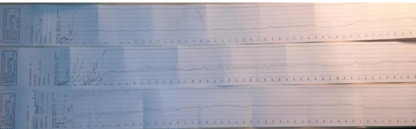
This device (Figure 1) is designed so that arborists are able to detect wood decay, stages of rot, hollow areas, cracks and ring structure (Allison and Wang 2015). As the micro drill enters the tree, the resistance of the wood causes increased power uptake in the drill. The instrument translates these variations into a diagram, which is printed by a Bluetooth printer (Figure 2) or may be downloaded to a computer.
Variations in drilling resistance are evident in the diagram; a region of lower resistance usually implies some form of internal damage (like rot or cavities).
Figure 1 – The Resistograph equipment
Figure 2 – Printouts of some Resistograph tests
More sensitive versions of the equipment have higher spatial resolution and can even detect variations due to different early wood and latewood density, and thus the annual ring structure can be examined.
One limitation of the device is that it should be precisely oriented so that the path of drilling goes through the decay zone, cavity or other internal anomaly in the trunk. It has been suggested that the resistograph technique is best suited to confirm and determine the extent of decay in trees after suspect trees are identified by other methods such as visual inspection, stress-wave timing or acoustic tomography (Allison and Wang 2015).
2.2.2. Impedance Tomography
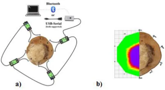
This equipment is able to detect the size and location of regions with active fungi attack in the trunk non-destructively It works based on electric resistivity measurements using several sensors around the trunk (Figure 3).
Figure 3 – Impedance Tomography (Vizvári, et al.2015)
The basic measurement principle is that electrical resistivity increases/decreases if there is a change in the concentration of ions in a certain region within the trunk.
Impedance tomography is based on creating an excitation field inside the trunk and measuring potential differences between several sensors around the circumference.
This allows the creation of a “resistivity map”, or tomogram, which may facilitate the detection of fungal attacks even in the very early stages when the mechanical performance of the tree is not yet affected, or when the disease does not affect the mechanical properties at all.
Electrical impedance tomography was first applied to wood by Just and Jacobs in 1998. After that there have been several applications of this technique, e.g. to detect decay (Dubbel et al. 1999, Bieker and Rust 2010a), red heartwood in beech (Weihs et al. 1999, Hanskötter 2004) and in wild service tree (Weihs 2001), and brown heartwood in ash (Weihs et al. 2005). It can also be used to determine the exact sapwood area in various species (Bieker and Rust 2010b, Lin et al. 2012), and to detect red hart in beach (Goncz et al. 2017).
2.2.3. Acoustic propagation time measurement
A simple acoustic wave propagation velocity measurement technique is based on measuring the sound propagation time (or Time of Flight, ToF) between two sensors, typically placed on opposite sides of the tree trunk (Figure 4). Measured propagation times are shorter in healthy material, but longer if there is decay in the measurement path, because the signal is usually forced to ‘detour’ around the decayed area. Wave velocity (calculated from the measured time and the distance of the sensors) is compared to a reference value (either measured on a healthy tree, or taken from literature, e.g. Divos and Szalai 2002) to determine the probable presence of decay.
Figure 4 – Schematic photo showing the operation principle of the Microsecond Timer (Divos et al 2011)
The stress wave timing method was first applied to determine degradation in trees by Mattheck and Bethge (1993), and has been in use as a simple yet effective technique since. While this technique can detect the presence of extensive decay with good probability, it cannot determine the extent or exact location of the damaged area.
2.2.4 Acoustic tomography
The acoustic tomograph is designed to detect hidden holes and decay in trees by non-destructive acoustic testing. The measurement is an extrnsion of the simple stress-wave timing technique, based on attaching several sensors around the trunk (Figure 5a), and measuring sound propagation time between each pair of sensors.
Data is then analyzed using reverse backpropagation to create a high-resolution sound-velocity map of the trunk cross section, where lower velocity regions may indicate decay, cavities or some other internal anomaly (Figure 5b).
Figure 5 – Acoustic tomography (Major & Divos 2015)
Several versions of acoustic tomographs have been developed and evaluated over the past two decades. It was successfully applied to detect internal decay hidden
from view within the trunk of trees (Nicolotti et al. 2003, Gilbert and Smiley 2004, Wang and Allison 2008, Wang et al. 2009.) Some versions of the available evaluation software is also capable of creating 3D maps by measuring several cross section layers of the same trunks at different height (Divos 2010).
2.2.5. Root Detection
The structure and condition of the root system has a very important effect on the health and stability of trees. Unfortunately, the position and condition of roots is very difficult to assess without excavating. Attempts to use nondestructive assessment included the use of ground penetrating radar (Guo et al. 2013) and nd electric resistivity tomography (Amato et al. 2008; Zenone et al. 2008).
More recently, an acoustics-based approach was presented for determining the location and orientation of the roots in the soil (Buza and Divos 2016). It works based on sound velocity measurements between a sensor attached to the trunk and a soil sensor placed close to the root (Figure 6). By adjusting the position of the soil sensor while keeping a constant distance from the trunk enables operator to map major roots that run close to the surface (Figure 7). The benefit of this method is that other trees’ roots, pipes or other buried materials do not affect the measurement.(Divós et al. 2009)
Figure 6 – Photograph showing the measurement principle used for root detection
Figure 7 – Demonstration of the results obtained from a root detector (Divós et al. 2009)
2.2.6. The pulling test
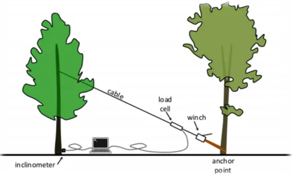
This technique is based on attaching a cable to the tree (at the approx. center of the crown), and exerting increasing lateral loads on the tree, while measuring the inclination of the root collar and/or the deformation of the trunk. The loading test is terminated at an inclination of 0.2 degrees, well before any damage could be caused to the tree. From the load-inclination or load-deformation curves, the uprooting or trunk failure moment can be estimated, and the safety of the tree concerning uprooting or breakage can be calculated, respectively, based on tree geometry and other factors.
Figure 8- Schematic view of the pulling test (Buza & Divós 2016)
The pulling test technique has been in use since the early 1990’s. Plenty of excellent papers are available on the implementation and the usage of these tests. Figure 8 (Bell et al. 1991; Wessolly 1991; Rodgers et al. 1995; Ray and Nicoll 1998; Neild and Wood 1999; Moore 2000; Peltola et al. 2000; Silins et al. 2000; Brudi and Wassenaer 2002; Clair et al. 2003; Lundström et al. 2007a, 2007b; Kane and Clouston 2008;
James and Kane 2008; Sani et al. 2012; Siegert 2013; James et al 2013; Rahardjo et al.
2014, Buza and Divos 2016).
At present, the pulling test is the most accepted method for evaluating the safety and stability of the root system. The advantages of this technique are discussed in chapter 1.2. Since this technique was used in our investigations, and because it is the basis of the dynamic tests as well, a detailed description of the theoretical background of this test is included in chapter 3.2.
2.3. Dynamic tree stability assessment
As shown in chapter 2.2, the currently accepted method of tree stability assessment is the static pulling test, despite its many disadvantages; chief among them is that it is a poor way of modeling the response of trees to actual wind loads (Moore and Maguire 2004). The reason for this is that the behavior of trees under actual wind load conditions is far from straightforward. Trees – especially open-grown trees, typical of urban situations – constitute a complex system of trunk, primary and secondary branches, twigs and leaves (James et al. 2006, 2014). Wind loading produces a chain reaction in these components in reverse order. Due to the complex interaction of the different components, the actual response of the tree is practically impossible to model or predict at our current scientific capabilities (Sellier and Fourcaud 2009). Further factors, like erratic wind gust intensities, natural variation of the material characteristics of the wood comprising the tree, etc. further complicate the situation.
In a relatively recent review article, James et al (2014) compiled a very thorough analysis of the available literature on the dynamic behavior of trees. In their study, they identified a number of hurdles that hamper the efforts to determine the mechanisms by which trees respond to wind loads, including:
the viscoelastic nature of wood, which results in non-linear deformations (Vogel 1996, Miller 2005);
exact material parameters are impossible to determine due to natural variation (Niklas 1992);
trees and other biological materials acclimate and can change their material properties as they age and grow (Lindström et al. 1998; Lichtenegger et al.
1999; Reiterer et al. 1999; Brüchert et al. 2000; Spatz and Brüchert 2000;
Lundström et al. 2008; Dahle and Grabosky 2010b; Speck and Burgert 2011)
Dynamic analysis is complicated because it includes all the static forces and additional components of inertial forces due to the motion, the damping
forces and the dissipation of energy, the displacement and phase differences, the natural frequencies, and the consequent changes in motion (Den Hartog 1956)
Damping is usually not well understood in vibrating structures (Clough and Penzien 1993) especially when it is complicated by non-linearity (Miller 2005)
Twigs, branches and trunk comprise a multi-degree of freedom system. A multimodal analysis is required to account for complex dynamic interaction of these components (de Langre 2008; Rodriguez et al. 2008)
In their study of tree aerodynamic behavior, Sellier and Fourcaud (2009) concluded that material properties play only a limited role in tree dynamics, while small morphological variations can produce extreme behaviors, such as either very little or nearly critical dissipation of stem oscillations. Indeed, ontogenetic morphological differences tend to have a major impact on the tree’s response to wind loading (Dahle and Grabosky 2010b; Speck and Burgert 2011).
In spite of the above issues, researchers employed various strategies to predict the behavior of trees in the wind. These include the following (based on James et al.
2014):
a) statistical evaluation of economic losses due to wind damage in forests (Moore and Maguire 2005; Peltola 2006);
b) assessment of the expected global behavior of trees under wind loading, e.g.
visual tree assessment (Mattheck and Breloer 1994), tree risk assessment methodology (Smiley et al. 2011), quantified tree risk assessment (Ellison 2005), and statics integrated methods that combine static pulling with dynamic wind load assessment (Wessolly 1991; Brudi and van Wassenaer 2002; Detter and Rust 2013).
c) wind tunnel testing (Peltola 2006); and d) dynamic tree modeling.
Unfortunately, the first three methods have their limitations in terms of accuracy.
Statistical economic evaluations cannot predict the behavior of individual trees at all, global tree behavior assessment methods tend to over-simplify tree behavior, and the limited size of wind tunnels allows the testing of scale models only, rather than actual trees, where the up scaling is complicated in terms for elastic, deformable bodies like trees, and loading tends to be static, rather than dynamic.
Dynamic modeling has the most potential to accurately recreate the dynamic loading situation that occurs in real life. Three types of models have been employed to simulate the dynamic behavior of trees, including the following:
The lumped-mass procedure, which assumes that the mass of each tree component is concentrated at a discrete point as it oscillates dynamically.
Components are regarded as interconnected spring-mass-damper systems (Figure 9). In its simplest form, the whole tree is regarded as a single system (e.g. Milne 1991; Miller 2005). However, realistic modeling requires a complex model of multiple interconnected lumped-mass components (James et al. 2006; Theckes et al. 2011; Murphy and Rudnicki 2012). Such systems tend to become very complex very fast, and their behavior exhibit multi-modality, which means that the harmonic movement of individual components may amplify or cancel each other out in a manner which is very difficult to predict. Nevertheless, the relative simplicity of the lumped-mass procedure is very helpful, particularly in describing the frequency- dependency of the trees’ behavior in dynamic loading scenarios (James 2010).
Figure 9– Dynamic models using a spring-mass-damper system representing: (a) a tree as a single mass (Miller 2005), and (b) as multiple masses with a trunk and branches (James et al.
2006).
Figure 10 – Dynamic modes applied to trees: (a) modes of a beam (Schindler et al. 2010) and (b) modes ofbranched structures (Rodriguez et al. 2008).
The uniformly distributed mass model provides a more accurate representation of tree components by treating each component as a beam
with distributed mass (Figure 10). However, it also makes the computations much more complicated, since not only does the interaction of the components exhibit modality, but each component may oscillate in different modes, which adds another level of complexity to the model. The groundwork for this method – the simple pole model – has been laid down as early as 1881 by Greenhill. The simplest model – a single beam with distributed mass – proved to be useful for analyzing the dynamics of trees growing in closely spaced plantations or forests (e.g. Bruchert et al. 2003).
However, the conspicuous lack of studies that would employ a more complex model to simulate tree behavior bears witness to the considerable complexity of this method.
Finally, Finite Element Modeling (FEM) combines the features of both the lumped mass and uniformly distributed mass procedures. It can handle any kind of structure (including trees), by breaking them down into smaller elements, and offers a good deal of flexibility. It can accurately represent relatively complex tree geometries, and has been successfully used to simulate various wind loading scenarios (e.g. Sellier et al. 2008; Sellier and Fourcaud 2009). On the other hand, its application requires accurate empirical measurement of many parameters particular to the tree and loading conditions to produce reliable results. It is a promising technique, but, again, realistic modeling requires a lot of computing power, and small inaccuracies in the initial/boundary conditions may lead to widely different simulation results.
Regardless of the particular modeling technique used, when representing complex entities like trees, a large number of parameters are needed to describe the material characteristics, morphology, the connections and mechanical behavior of trees, even in a relatively simple case. Also, the computing power required for modeling a given scenario is often prohibitive.
For this reason, any kind of modeling requires a good deal of simplifying assumptions, which introduces a certain amount of calculated inaccuracy or uncertainty in the simulation. This is generally acceptable in most modeling or simulation studies. However, as mentioned before, when modeling trees, even small morphological variations or inaccuracies can lead to widely divergent results, and the same is true for small differences in the boundary conditions.
In fact, the behavior of the various components – trunk, branches, twigs – is not unlike that of a multiple damped pendulum (Bejo et al. 2017). The branches and the trunk constitute a nonlinear vibrating system that behaves very erratically. The behavior of such systems is extremely sensitive to the initial boundary conditions, and is virtually impossible to predict long term. This type of behavior is called chaotic motion, and multiple pendulums are also dubbed chaotic pendulums for this reason.
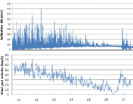
The reason that the dynamic modeling techniques mentioned earlier generally fail to adequately describe the behavior of trees is that unfortunately this type of nonlinear and chaotic system is virtually impossible to model by deterministic methods. This is the reason why there appears to be no direct relationship between momentary wind velocity and the inclination of the trunk. In fact, in high wind gusts the tree often remains relatively stable, while sometimes in a relative lull significant loss of stability is observed (see Figure 11). This phenomenon goes well beyond a simple time lag; it appears almost completely random (Divos et al.
2015).
Figure 11 – Simultaneous inclination and wind velocity data showing no immediate correlation between the two factors (Bejo et al. 2017.)
However, chaotic systems may be studied using statistical methods (Strogatz 2014). In the long run, such systems will realize all possible states, and the statistical parameters of the measured variables over a certain period provide meaningful information. E.g. while there is no direct relationship between momentary wind load and inclination, average wind speed and average inclination values taken over longer periods (e.g. 1, 5 or 10 minute intervals) exhibit a similar relationship as that found between load and inclination during static testing.
This is the principle behind the dynamic tree stability assessment technique used in our study. A more detailed description of the measurement principle will be presented in chapter 3.3.
2.4. Factors influencing tree stability
Water, carbon dioxide, soil, sun, mineral nutrients and etc. are elements that trees need for growth. Deficiencies of these raw materials affect the health and stability of trees. The location of the trees also plays an important role in the stability of the trees.
Sunlight is the biggest source of energy for the trees. However, sunlight is not equally distributed around the globe. This means that trees do not receive the same amount of sunlight in their different parts. Sometimes even they grow up with angle to reach to sunlight and when they become taller and taller they’ll have problem with self-weight and it make problem for their stability. On the other hand, as clear in the forest (not planted) the trees are somehow very close to each other in this case they start to competition together to reach sunlight. Only trees that succeed in growing towards sunlight will be able to survive.(Wessolly and Erb 2016)
The other impact is wind load. Wind is depending to 2 quantities: velocity and pressure. Three different conditions determined these two parameters: geographical situation, topographical situation and seasonal and meteorological influences (Wessolly and Sinn 1989).
Asymmetric tree crown is another element that may decrease tree stability. This may occur when trees grow on a slope, around an obstacle or in close proximity if buildings (Coomes & Allen 2007).
The root system has a crucial effect on the stability of trees. There are 3 types of root systems depending on species; surface root, heart root and taproot system.
Furthermore, there are different soil properties, such as moist, rock, sandy soils, clay soils, pot plant effect and the effect of fertilization could affect the stability of trees (Wessolly and Erb 2016).
Several problems could pose risks for the stability of the trees that are caused by
breakage, sun scald, frosts, climbers and the dieback of main roots, tree bark parasites, bark beetle, vascular diseases, root parasites. Some more problems happen by human interference. This kind of problem usually happens in urban areas where trees are in touch with human life. These problems include construction work, changes in the water table, trees suddenly becoming solitary, demolition of a wall above the root zone close to the tree trunk, compacted soil in the root zone – reduced oxygen content in the root zone, soil sealing, backfilling, soil excavation, excavation with or without machinery, root cutting, injuries, thermal radiation emitted by buildings, construction damage, car accident by tree, pollution, bonfires, compost heaps, natural gas, vandalism, crown reduction, tree surgery. (Chodak 2019)
Species have a very important effect on the stability of trees. General categories include broad leaves and conifers, but these categories may be broken down furhter based on crown and root morphology and other factors. Each category has its own unique properties. (Barbier et al 2008)
Many studies on conifer seedlings show that root deflection in propagation containers can contribute to long-term growth problems after planting in the forest (Krasowski 2003). Wood and most materials that come from plants are described as viscoelastic because their mechanical behavior contains both elastic and viscous elements (Miller 2005). These properties result in nonlinear behavior. Evidence of the influence of tree architecture on wind firmness has also been shown by Fourcaud et al. (1999) who carried out mechanical studies on two rubber tree clones that had similar wood properties but dissimilar crown structures (Cilas 2004). The shape and structure of trees has an important impact on their mechanical stability under dynamic loading. As trees grow, the added biomass translates into greater dead weight, and the upper parts of the tree are exposed to higher wind speeds, creating larger bending moments at its base (Niklas & Spatz 2000).
Yang et al. (2010) explored the influence of root moisture content on the tensile resistance and strength with different root diameters and for different tree species.
The results showed that root moisture content affected the tensile properties. A slight loss of root moisture content could enhance tensile strength, but too much loss of water resulted in weaker capacity for root elongation with tensile resistance.
The main factors contributing to slope stability include soil shear strength, soil-root interactions, the quantity and distribution of roots, as well as root tensile properties (Genet et al 2005).
Chapter III. Theoretical background
3.1. Tree biomechanics
Brudi and Wassenaer (2002) provided a very detailed review of tree biomechanics, based on a statics approach. In their model, just like in the engineering design of man-made structures, wind loads acting on trees are counteracted by the load- bearing capacity of the tree, which is determined by material properties on the one hand, and the geometry of the tree on the other. This model can be applied both to the safety of trunk (or indeed, that of larger branches) against breakage, and to the stability of the tree against uprooting.
Of course, this very simple model becomes considerably more complicated when looking at the real life situation of trees. First of all, wind intensity and wind pressure depend on three different factors:
Geographical location
Topological situation
Seasonal and meteorological influences.
Wind speeds are not constant, but increase with altitude following a parabolic profile. The exact wind speed distribution also depends on the surface roughness of the terrain. For practical consideration, trees are usually evaluated using these profiles, based on the expected maximum wind speed in the given geographical location.
Once the maximum wind speed (and, from that, the maximum wind pressure, or pressure profile) is established, maximum expected wind loads may be calculated for the tree. This load can be used to calculate the maximum bending moment the trunk of the tree is likely to experience, and also the maximum tipping moment
that the tree needs to withstand without uprooting. The latter is important for the purposes of our study.
Wind pressure is calculated from wind velocity using the simple equation below:
⁄ , (1)
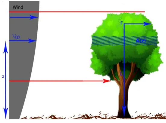
where is the density of air, and v is wind velocity. We can calculate the wind load (lateral force) from the wind pressure, by multiplying it with the area of the crown. This is the force that acts on the crown of the tree, and creates torque on the tree trunk. This torque is maximal at the root collar, where the lever arm is the longest.
In actuality, of course, because of the uneven vertical distribution, different portions of the crown experience different wind pressures, and also the distance of these parts of the crown is different from the ground. Figure 12
Figure 12- Influence of the load component (Wessolly 1998)
⁄ ∑ , (2)
where: A – surface area of a portion (a horizonatal “slice”) of the crown z – vertical position (distance from the ground).
In practical investigations the above formula is typically too tedious, and the vertical pressure distribution is replaced by a constant effective pressure value, and the equation is simplified, as follows:
⁄ (3)
where: Acrown – crown surface area hcent – crown centerpoint height.
Figure 13 – Wind resistance of tree crowns and the aerodynamic drag factor (cw) (based on Davenport, 1965)
The situation is further complicated by the fact that strong winds can deform the crown of the tree, whose area and center point height are also significantly altered.
This is handled by introducing a so-called aerodynamic drag factor (cw) in the
equation. The value of this factor depends on wind intensity (see Figure 13), and is also species-dependent. Therefore, the final equation for determining wind-induced torque on the root collar is, as follows:
⁄ , (4)
Substituting maximum wind pressure/velocity (pmax/vmax) in the above equation allows the calculation of the maximum moment (Mmax), i.e. the largest level of torque the tree needs to withstand without uprooting. Drag factor values for different species have been determined through extensive experimentation, and can be found in the work of Brudi and Wassenaer (2002).
3.2. Traditional tree stability assessment
As mentioned in chapters 1.2 and 2.2, the traditional method of assessing tree stability is the pulling test. This test was developed based on the engineering principles outlined in chapter 3.1.
The test involves fixing a rope in the tree crown, approx. at centerpoint height, and achoring it somewhere close to the ground. After that, a gradually increasing pulling load is applied through the cable, while measuring the inclination of the root collar. This provides a load-deflection curve, which follows a special tangential relationship (Figure 14), according to equation (5):
Figure 14 – The tangential relationship between load and inclination experienced during the pulling test (Bejo et al 2017)
(
) (
)
, (5) where: – the inclination of the root collar,
F – horizontal load,
Fcrit – critical horizontal load (uprooting force).
The above relationship has been verified by testing a large number of trees that all followed this behavior (Brudi and Wassenaer, 2002).
Naturally, trees are not tested all the way to uprooting, but released after an inclination of 0.2 degrees is reached, well before any damage could be done to the tree. Fcrit is then estimated through extrapolation by fitting the relationship described by eq. (5) to the measured data point. From Fcrit and the height at which the cable has been attached to the tree, Mcrit (the uprooting moment) can be calculated. This is the torque required to uproot the tree.
Finally the stability of the tree is characterised by the so-called Safety Factor (SF), determined as the ratio of Mcrit and the maximum moment (Mmax) determined from the critical wind pressure using eq. (4):
, (6)
Note that Mmax is always determined relative to a certain reference wind velocity level (the highest wind likely to occur at the given geographical area). Theoretically, as long as Mcrit > Mmax, (i.e. SF > 1) the tree is safe at the reference wind velocity.
However, since Mcrit is only a prediction (albeit usually very accurate), and because of possible uncertainties in the determination of the reference wind velocity and the geometric parameters, the tree, by convention, is considered safe if SF > 1.5 and unsafe if SF < 1. Between 1 and 1.5 there is a region of uncertainty, and one should exercise caution (Brudi and Wassenaer 2002).
3.3. Dynamic tree stability assessment
Dynamic testing is based on the same principles as the static test, except the static horizontal load is replaced by actual wind loading. However, as mentioned in chapter 2.3, there is no direct relationship between momentary wind pressure and the inclination of the root collar, due to the chaotic response of trees to dynamic wind loading. However, while there is no immediate relationship between these parameters, statistical methods can often be employed on chaotic systems to find meaningful relationships (Strogatz 2014). For example, the wind load and inclination diagrams introduced in Figure 1 can be broken down into longer intervals, and statistical parameters (e.g. the average over a 5 or 10-minute period) can be calculated, as shown in Figure 15. It is evident from these diagrams that, while momentary values cannot be correlated, the averages (indicated by red lines in the figure) are in relatively good agreement.
Figure 15 – Breaking down dynamic wind load and inclination data into batches to calculate statistical parameters
By measuring the wind intensity and root collar inclination over longer periods of several hours, grouping them into batches of several minutes, and calculating the
averages, similar load and inclination data pairs can be obtained as the ones used for evaluating pulling test results. There are only two important differences:
1. Data points are not consecutive but random
2. Instead of horizontal force, wind velocity or wind pressure is measured The first issue is inconsequential since curve fitting can be executed regardless of the order of the points, as long as enough data points are available. The second issue means that the calculation of the Safety Factor is slightly different, since wind load is substituted for the static load employed to determine Mmax. Therefore, equation (6) can be expressed, as follows:
, (7)
Notice that by substituting wind pressure for the calculation of the critical and maximum moments, the crown area and crown center point height cancel out in the equation, since these parameters are the same whether we are considering maximum or critical wind pressure. The situation is less straightforward in case of the drag factor, which depends on wind intensity, and does not affect the low-wind section of the curve as much as the high wind area. However, using the same, high cw value throughout the curve results in conservative estimation, and allows the drag factor to cancel out too.
Thus, the equation is reduced to the ratio of critical wind pressure to maximum wind pressure (the wind pressure belonging to the highest expected wind velocity).
Critical wind pressure (pcrit) is determined from the pressure-inclination curve the same way as Fcrit is determined from the load-inclination curve. The safety factor determined this way is not only simpler to calculate, but likely to be more relevant to the dynamic loading situation that trees experience in the wind.
3.4 Factors influencing tree stability
There are many factors that influence tree stability (i.e. the tree’s resistance against uprooting). Some of these, like crown shape and surface area, age, etc. are intrinsic properties of the tree, and are taken into consideration when assessing the stability of the trees. There are also external factors that impact the stability significantly.
The most important of these natural and anthropogenic factors are discussed in this chapter.
3.4.1 Seasonality
In temperate climates, the seasons affect the growth, metabolism and general activity of trees. This also influences the stability of trees in several different ways, as follows:
3.4.1.1. Foliage changes
The changing of the seasons has a major effect on the foliage of broadleaved species. This also has a major impact on tree stability, since leaves significantly increase the crown surface, and transfer much of the wind loads to the system of twigs and branches, and eventually, through the crown, to the root system. On the other hand, leafy crowns suffer more deformation in the wind, which may decrease the crown surface, as expressed by the aerodynamic drag factor.
In conifers, this effect is much less pronounced, or may be altogether absent, since their crown surface area and aerodynamic drag factor do not change dramatically in the winter (except for some rare exceptions, like larch, which sheds its needles in the winter).
3.4.1.2 Biological activity
In general, trees are biologically much more active in the spring and summer, and tend to decrease their activity, and eventually go dormant in the winter. This affects the root system, which tends to swell and be more firmly anchored in the soil in the spring and summer, due to the increased sap flow, and become somewhat looser in the autumn and winter. This affects the stability of all trees adversely, albeit not nearly as strongly as the foliage change in broadleaved trees.
(Bieker et all 2010)
3.4.1.3 Other seasonal factors
Seasonal changes also affect tree stability through changes in temperature.
Particularly, the frozen soil in the winter may become much more resistant against uprooting, which will positively influence the stability of the tree. The nature of precipitation also tends to change in the winter, but this will be discussed in the next chapter.
3.4.2 Precipitation
Precipitation will also affect the stability of trees. The effect is markedly different depending on the form of precipitation.
3.4.2.1 Rain
Rainy weather – especially when it’s prolonged – affects both the tree and the soil.
Rain-covered foliage will have a somewhat increased inertia, but the effect is much more pronounced in the soil. Rainwater penetrates the ground, and loosens the soil, which will therefore allow more movement, and become less resistant to uprooting. Both of these effects will act towards decreasing tree stability.
3.4.2.2 Snow
Snow will also tend to decrease tree stability, but through a different mechanism.
Snow will not penetrate and loosen the soil. Instead, it will accumulate on the branches (and, in the case of conifers, needles) of the tree. Sometimes the accumulation can be quite significant, and the weight of the snow will considerably increase the inertia forces, when the tree is moved by wind, and will therefore lead to increased loads. The weight of the snow will also push the tree into the ground and help anchor it, which will alleviate the increased loading to a certain extent.
Nevertheless, snow loads tend to decrease tree stability, although not as much as the seasonal foliage changes. (Sleet will also have a similar effect.)
3.4.3 Wind direction
The wind direction in most locations is not completely random. Each geographical area will have a so-called prevailing wind direction, i.e. the point of the compass where the wind most frequently blows from. During its development, this is the wind that the tree most frequently experiences, and therefore this is the direction in which it will develop the highest resistance against breakage and uprooting.
3.4.4 Root damage
Root damage is most often an anthropological issue. It occurs most frequently in urban environments, when various structures like roads or buildings are built in the vicinity of trees. Cutting the roots has a twofold consequence. On the one hand, roots absorb water and nutrients from the soil, and some of this is interrupted when roots are damaged. On the other hand, roots serve as anchorage for the tree; cutting the roots therefore obviously decreases the stability of the tree.
For significant stability loss to occur, a considerable portion of the roots needs to be cut. This also depends on the root system structure; trees with extensive, superficial roots are affected more badly by relatively shallow structures (e.g. when
constructing roads or pipelines running close to the surface), while deeper, taproot systems are less susceptible to this, and are only affected when constructing underground structures underneath them.
3.4.5 Pruning
Pruning is another type of artificial intervention, done to the tree intentionally. It is a silvicultural practice that is used to improve wood quality. Pruning is also used in urban environment, sometimes for aesthetic reasons, or to remove branches that interfere with manmade structures, or sometimes to improve trunk safety and stability by reducing the crown area.
The reduction of the crown surface means that there is a smaller area for the wind to act upon. This results in lower loads at the same wind intensity, and, ultimately, improved safety and stability. The effect of pruning is different from the effect of defoliation of broadleaved trees in the autumn in that in this case the branches are also removed, in addition to the leaves.
Chapter Ⅳ. Equipment and Methods
Research objectives were fulfilled via various experiments, as follows:
comparing the results of the traditional static pulling test with those of the new dynamic method, and validating the results against the uprooting moment required to pull up some diseased trees;
measuring trees in different weather and seasonal conditions to build a database and draw conclusions regarding the influence of various factor on the stability of coniferous and deciduous trees;
assessing the influence of anthropogenic factors such as pruning and root system damages on the stability of trees.
In this chapter, both the equipment and the experimental methods will be described.
4.1. Equipment
In the research work two different pieces of equipment were used: the DynaRoot system and pulling test.
The DynaRoot system is completely nondestructive method, while in the case of pulling test, the force is exerted mechanically, but, in normal cases, it does not cause any damage to the tree. When the pulling test is prolonged, it can be used for uprooting the tree when using a high level of force. In this chapter a detailed explanation about the two kinds of equipment, as well as the Arborsonic software will be given.
4.1.1. Pulling test
The pulling test (Figure 16) consists of:
Cable and winch: our system contains a 20-meter length of high capacity metal cable with a 1.6 metric ton manually operated winch. The winch has a ratchet mechanism that multiplies the force of the operator to exert sufficient tension on the cable. The cable and the winch were equipped with safety hooks and two soft belts for fitting it around the tree trunk and the anchor point.
Load cell: calibrated cable-mounted load cell, 5T capacity with a sampling rate of 1 Hz.
Inclinometer: biaxial inclinometer sensor, ST-015 mounted on the tree collar with a measurement range of ± 2 degrees, and a resolution of 0.001 degree.
Figure 16 – Schematic view of the pulling test