cylinder liner – piston ring contact
Thomas Wopelka
AC2T Research GmbH, Wiener Neustadt, Austria
Ulrike Cihak-Bayr
Department of Tribodesign and Tribodiagnostic, AC2T Research GmbH, Wiener Neustadt, Austria
Claudia Lenauer
AC2T Research GmbH, Wiener Neustadt, Austria
Ferenc Ditr oi and Sándor Takács
Institute for Nuclear Research, Hungarian Academy of Science, Debrecen, Hungary, and
Johannes Sequard-Base and Martin Jech
AC2T Research GmbH, Wiener Neustadt, Austria
Abstract
Purpose–This paper aims to investigate the wear behaviour of different materials for cylinder liners and piston rings in a linear reciprocating tribometer with special focus on the wear of the cylinder liner in the boundary lubrication regime.
Design/methodology/approach–Conventional nitrided steel, as well as diamond-like carbon and chromium nitride-coated piston rings, were tested against cast iron, AlSi and Fe-coated AlSi cylinder liners. The experiments were carried out with samples produced from original engine parts to have the original surface topography available. Radioactive tracer isotopes were used to measure cylinder liner wear continuously, enabling separation of running-in and steady-state wear.
Findings–A ranking of the material pairings with respect to wear behaviour of the cylinder liner was found. Post-test inspection of the cylinder samples by scanning electron microscopy (SEM) revealed differences in the wear mechanisms for the different material combinations. The results show that the running-in and steady-state wear of the liners can be reduced by choosing the appropriate material for the piston ring.
Originality/value–The use of original engine parts in a closely controlled tribometer environment under realistic loading conditions, in conjunction with continuous and highly sensitive wear measurement methods and a detailed SEM analysis of the wear mechanisms, forms an intermediate step between engine testing and laboratory environment testing.
Keywords Surface analysis, Wear testing, Sliding wear, Internal combustion engines, Boundary lubrication, Radioactive isotopes, Tribometer testing
Paper typeResearch paper
1. Introduction
Reduction of exhaust gas emissions and fuel consumption to minimise environmental pollution and to fulfil governmental regulations are major driving forces for the improvement of modern combustion engines. Recent technological developments have not only led to engines with higher power density to increase the efficiency but also to the application of lighter materials (instead of conventional cast iron) for the cylinder block (Tung and McMillan, 2004), aiming to decrease fuel consumption by weight reduction. Another way to decrease fuel consumption is the reduction of friction losses of the piston ring and cylinder liner system, as this contact is responsible for a large fraction of the total friction losses of a
vehicle equipped with an internal combustion engine (Taylor, 1998; Tung and McMillan, 2004). To optimise the whole cylinder and piston ring tribosystem, the material of the ring also has to be adapted according to the material chosen for the cylinder liner. The functionality of the cylinder and piston ring contact has to be guaranteed over the whole lifetime of the
The current issue and full text archive of this journal is available on Emerald Insight at:www.emeraldinsight.com/0036-8792.htm
Industrial Lubrication and Tribology 70/4 (2018) 687–699
Emerald Publishing Limited [ISSN 0036-8792]
[DOI10.1108/ILT-07-2017-0218]
© Thomas Wopelka, Ulrike Cihak-Bayr, Claudia Lenauer, Ferenc Ditroi, Sándor Takács, Johannes Sequard-Base and Martin Jech.
This work was carried out at the“Excellence Centre of Tribology” –AC2T research GmbH, Wiener Neustadt, Austria, in the frame of the Austrian COMET Programme (Project K2, XTribology, no. 824187/849109) in close collaboration with AVL List GmbH, Nemak Dillingen GmbH, Nagel Maschinen- und Werkzeugfabrik GmbH and the Institute for Powertrains and Automotive Technology. The authors would like to thank Lukas Spiller who operated the tribometer equipment and performed the wear measurement and Karoline Steinschütz who carried out the wear data analysis of the RIC and microscopy measurements.
Received 26 July 2017 Revised 18 January 2018 Accepted 22 January 2018
engine. This long-term functionality can deteriorate due to piston ring and/or cylinder liner wear.
For these reasons–weight reduction, reduction of friction losses and wear protection–a variety of material combinations for cylinder liners and piston rings are used in modern combustion engines. For example, the use of hypereutectic AlSi alloys as liner material leads to a weight reduction of up to 50 per cent of the engine block. However, the wear resistance mechanisms of these materials (Dwivedi, 2006; Grünet al., 2012) are still discussed in literature, where the explanations reach from the formation of anti-wear additive pads on the Si particles (Nicholls et al., 2005; Pereira et al., 2005) to the embedding of Si wear particles into the Al matrix (Dienwiebel et al., 2007). Another common practice is to combine the advantages of weight reduction of the block with the good wear resistance of iron-based materials by applying iron-based coatings, e.g. with the plasma transferred wire arc (PTWA) process (Bobzinet al., 2007).
For an optimised tribosystem, not only the cylinder material itself but also the choice of the piston ring material is important.
Typically, nitriding is a standard surface treatment for steel piston rings. Alternatively, Cr-based PVD coatings, as well as diamond-like carbon (DLC), are increasingly used (Friedrich et al., 1997;Tunget al., 2003).
In internal combustion engines, the wear behaviour is influenced by a variety of different parameters, such as mechanical loading conditions and corrosive effects and oil ageing, as well as interactions between these mechanisms. In tribometer tests, the test parameters can be adjusted separately, which allows investigation of isolated effects of specific parameters (Johanssonet al., 2011). Furthermore, the absence of the combustion process in a tribometer enables elimination of the effects of soot, corrosive combustion products or transient loading conditions to focus on the influence of the material combination under well-defined conditions.
Wear in the piston ring–cylinder liner contact is highest for the top dead centre (TDC) during the power stroke (Priest et al., 1999), as the contact pressures are high and the lubricant film is thin and boundary lubrication may occur for several engine loading conditions. In literature, a relatively wide range of contact pressures can be found for the contact situation between the top compression ring and the cylinder wall at TDC. The contact pressure values depend on assumptions regarding ignition pressure and engine parameters.
Furthermore, different models are chosen to calculate the pressures, taking into account lubricant supply for the piston rings, oilfilm temperature, oilfilm thickness or occurrence of cavitation.
Priest and Taylor (2000) mentioned a typical maximum pressure of 70 MPa for the contact between the top compression ring and the cylinder liner in modern four-stroke gasoline engines.Chonget al. (2011)calculated the contact pressure using a modified Elrod equation, taking into account the lubricantfilm formation and cavitation in the oilfilm due to the motion of the piston rings. They assumed a combustion pressure of approximately 1.75 MPa and obtained a contact pressure of approximately 20 MPa in the TDC during ignition.
Mishraet al.(2008)calculated the contact pressures between the piston ring and the cylinder wall by applying a series of quasi-static analyses based on elasto-hydrodynamic lubrication
and Reynolds’equation. Assuming a combustion gas pressure of 12 MPa at TDC for a certain gasoline engine type, they calculated a peakfilm pressure at TDC during the power stroke of about 290 MPa. Other groups tried to adjust the piston ring and cylinder contact pressures in the tribometer setup in accordance to the situation in the real engine at TDC.
Johanssonet al. (2011)used the Hersey parameter (Hersey, 1966) (which is a combination of contact pressure, velocity and dynamic viscosity) to transfer the conditions in the real engine to the tribometer setup, and obtained contact pressures for the experimental setup in the range of 70 MPa to 140 MPa.
Truhanet al.(2005a) used bench tests with Hertzian stresses of approximately 350 MPa to replicate heavy duty diesel engine conditions of approximately 50 MPa.
This study investigates the influence of the material pairing and the corresponding mechanical effects on the wear behaviour of the cylinder liner in the cylinder liner–piston ring contact using model tests with parameters chosen to replicate the TDC pressure conditions. Other effects, such as combustion products or thermal oil ageing affecting the lubricant and the investigation of tribofilms, are deliberately excluded.
2. Experimental setup 2.1 Samples
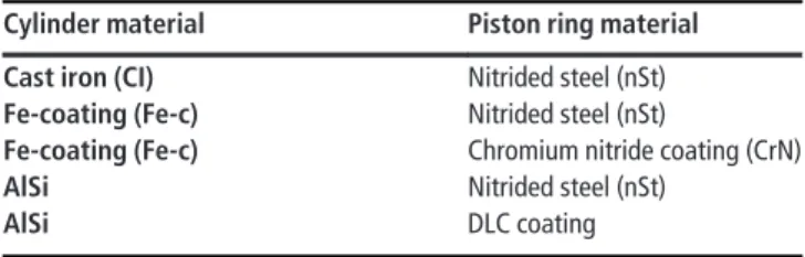
Certain material combinations commonly used in combustion engines were tested (Table I). Cast iron cylinder liners, liners with an iron-based coating (Fe-coated cylinder liners) and AlSi cylinder liners were all run against nitrided steel (nSt) piston rings in tribological tests. The Fe-coated cylinder material was also tested against piston rings with a chromium nitride coating (called CrN rings in the following) and the AlSi cylinder material was tested against DLC-coated piston rings acting as the counteracting body.
The Fe-coated cylinder samples were produced by a PTWA process with the coating being applied on Al-alloy liners. The cast iron and AlSi liners werefinished with a similar honing technique, whereas the Fe-coated samples werefinished with a different honing procedure. The honing procedure for the Fe- coated samples led to shallower grooves compared to the cast iron and AlSi liners. The Fe-coated surfaces therefore appear smoother, but pores that can act as oil reservoirs are present.
All samples were cut from original engine parts and all material pairings were tested with their unmodified, original surface topography. Therefore, not only the material compositions but also the actual surface roughness changed with varying sample pairings. Surface topographies and roughness parameters before and after all tests were determined with a Leica DCM 3D confocal microscope.
Table I Material pairings for the tribometer tests
Cylinder material Piston ring material
Cast iron (CI) Nitrided steel (nSt)
Fe-coating (Fe-c) Nitrided steel (nSt)
Fe-coating (Fe-c) Chromium nitride coating (CrN)
AlSi Nitrided steel (nSt)
AlSi DLC coating
2.2 Tribometer setup
In combustion engines, the top piston ring is exposed to a variety of tribological conditions–covering boundary, mixed and hydrodynamic lubrication regimes–facing a wide range of sliding velocities and contact pressures. The highest pressures between the piston ring and the cylinder liner occur at the TDC during the power stroke. At this position, sliding velocities are small and starved lubrication or boundary lubrication is likely to occur (Priestet al., 1999;Cho et al., 2000;Morriset al., 2013). Thus, the highest wear rate in the piston ring and cylinder liner contact usually occurs at the TDC position during the power stroke. Wear can also occur at the bottom dead centre, but usually to a lesser extent, or the mid-stroke region, when abrasive particles are present. At the bottom dead centre, the sliding velocity is also small, but the contact pressure is mainly due to the ring pre-compression. In the mid-stroke region, the main causes of wear are the wobbling motion of the rings and the presence of wear particles. However, the wear behaviour of these zones is not the focus of this work.
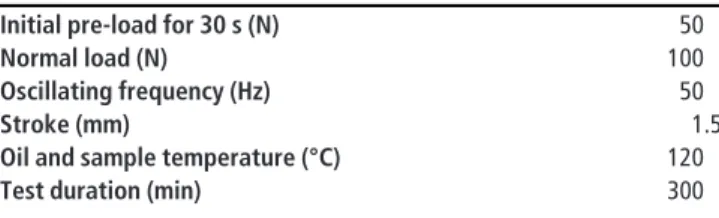
As the highest wear rates of the piston ring and cylinder liner contact occur in the TDC position during the power stroke, the setting of test parameters (Table II) was chosen to model these tribological conditions specifically with respect to the contact pressures discussed in the introduction chapter.
The tribological tests were carried out on a tribometer with linear reciprocating movement based on the standards for evaluating lubricants with respect to their wear prevention capabilities (DIN 51834-1 DIN 51834-2), but adapted to the necessities for continuous wear measurement of engine components samples. Piston ring and cylinder liner samples (Figure 1) were mounted in the tribometer test chamber using a sample holder designed specifically for this setup. A lubricant circuit was applied to provide a constantflow of engine oil for
the tribological contact zone between the ring and the liner.
The sample holder includes a soft plastic enclosure that prevents oil loss during the tests. The test setup of the tribometer with the mounted samples, the oil circuit and the detector unit is shown inFigure 2.
In engines, ignition causes rapid changes in contact pressure, leading to dynamic loading conditions. In contrast, the tribometer conditions (Table II) were chosen to have constant loading conditions and represent the lubrication situation close to the TDC during the power stroke, as this is where the highest wear rate can be expected. The contact situation will be explored further in the discussion.
Standard SAE 5W30 fully formulated engine oil was used as lubricant for all experiments. Only fresh lubricant and fresh samples were used for each test. Other effects, such as corrosion or the influence of oil ageing due to combustion products or the formation of tribofilms, on wear behaviour were not investigated in this work. The test duration of 300 min was adequate to study the running-in and steady-state wear behaviour with sufficient resolution.
Three tests were performed for each combination of cast iron cylinder–nSt ring and AlSi–nSt ring, whereas two tests were carried out for the pairings Fe-coated cylinder–nSt ring, Fe- coated cylinder–CrN ring and AlSi cylinder–DLC ring.
2.3 Wear measurement
2.3.1 Wear measurement–radio isotope concentration method The radioactive isotope concentration (RIC) method (Jech, 2012; Bianchi et al., 2017) was used to measure wear continuously throughout the tests, including running-in and steady-state wear. To determine the amount of wear of the cylinder liner materials, radioactive tracer isotopes were produced within a thin surface layer of the cylinder samples at the designated contact zone. The production of tracer isotopes was carried out in a dedicated beam line of the cyclotron of the Institute for Nuclear Research (Debrecen, Hungary) by bombarding the sample surface with a charged particle beam of protons and deuterons in air or in nitrogen atmosphere, which produces gamma-ray-emitting isotopes (56,57Co,65Zn,. . .) with known depth profiles of activity concentration near the specimen surface (Ditroi et al., 1997; Takacs et al., 2007).
The bombarding energy of the activating charged particles and Table II Settings of test parameter
Initial pre-load for 30 s (N) 50
Normal load (N) 100
Oscillating frequency (Hz) 50
Stroke (mm) 1.5
Oil and sample temperature (°C) 120
Test duration (min) 300
Figure 1 Piston ring sample (left) and cylinder liner sample mounted in the bottom part of the tribometer sample holder (right)
Figure 2 Test setup showing the tribometer with the mounted samples, the RIC detector unit and the pump for the oil circuit
the irradiation angle were selected in such a way that the depth distribution of the produced main isotope (Table III) corresponds to the expected wear range of the part/material in question. The irradiation dose was designed in such a way that the total activity of the sample (s) sent in a single package and/
or used in a measurement do not exceed the free handling limit (Ditroi et al., 2012). The samples were measured after the irradiation with high-resolution gamma-spectrometer to certify the activity of the main and the co-produced radio-isotopes.
The types of accessible isotopes depend on the material composition of the sample and the beam parameters.Table III shows the original element and the tracer isotopes produced during activation for each cylinder material. The concentration of tracer isotopes is in the range of ppb.
The wear particles generated during the tribological experiment are transported to a gamma radiation detector via the closed lubricant circuit. With the knowledge of the depth profile of the activity concentration in the investigated specimen, the measured activity signal can be converted to a wear volume. An average wear depth can be calculated by dividing the measured volume by the area of the wear mark and can thus be interpreted as an average depth over a uniformly worn area. Wear is given as wear depth in this paper because this quantity is often used in engineering science, as it is more tangible than wear volume or mass loss.
Separation of running-in and steady-state wear is important, especially when the long-term behaviour of a tribosystem (lifetime) is estimated on the basis of short-term tribotests.
Figure 3shows the definitions for running-in and steady-state wear for a typical wear curve obtained with the RIC method.
The steady-state wear rate is defined here as the slope of the linearfit in the steady-state wear region, whereas the running-in wear is defined as the y-abscissa of the linearfit (i.e. the wear depth extrapolated to the start of the test).
2.3.2 Wear measurement–differential surface topography
In addition to the wear measurement with the RIC method, the total amount of wear of each cylinder at the end of the tribological process was measured optically using the differential surface topography (DST) method (Vorlauferet al., 2010). For the DST method, reference marks have to be imprinted on the specimen surface in an area that is not subject to wear. Indents positioned near–but outside–the area of the designated contact zone serve as such reference marks.
Topographical images (made with a Leica DCM 3D confocal microscope) of the samples taken before and after the test can be aligned precisely with a special algorithm using these indentations. Then the wear volume and the average wear depth can be calculated via pixel-wise subtraction of the aligned images, with the average wear depth being the arithmetic mean of the height differences of all pixels. As images are only taken before and after the test, it is not possible to distinguish between running-in and steady-state wear with the DST method and only the total wear at the end of the test can be determined.
3. Results
3.1 Friction coefficient
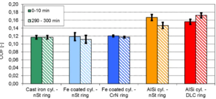
The coefficient of friction (COF) was measured continuously throughout the tests. To identify changes in the friction coefficient over time, the average friction coefficients during the first 10 min (0-10 min) and the last 10 min (290-300 min) of the experiment were compared. Figure 4 shows the mean values and the standard deviations of these average friction coefficients for each material pairing.
The material pairings with the AlSi cylinders show higher friction coefficients than the other material pairings. For the material combination DLC ring-AlSi liner, the friction coefficient increased during the tribometer test. When the counterpart of the AlSi cylinder sample is a nitrided steel ring, the opposite occurs and the COF decreases during the test. For the other combinations, the friction coefficients remain constant or show a slight decrease within the standard deviations throughout the tests.
3.2 Roughness
The Rq parameters–the root mean squares of the roughness profiles (DIN EN ISO, 4287)–of the cylinder liners and piston Table III Original elements for activation and produced tracer isotopes
cylinder liner materials
Material Original element Tracer isotope
Cast iron (Cyl.) Fe 57Co
Fe-coating (Cyl.) Fe 57Co
AlSi (Cyl.) Cu 65Zn
Figure 3 Characterisation of running-in and steady-state wear Figure 4 Coefficient of friction for different material pairings
rings were determined with confocal microscopy before and after the tribological experiments.
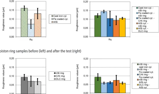
Before the wear test (Figure 5, left), the Fe-coated cylinder samples have the lowest initial Rq, which is a result of the different honing process. The initial Rq values of the cast iron cylinders are slightly higher than the AlSi cylinder Rq values.
After the wear test (Figure 5, right), the Rq values of the cast iron and AlSi cylinders are lower than those before the test, whereas the Rq values of the Fe-coated samples are higher than those before the tribotest. Using nitride steel rings as counterparts to the Fe-coated liners leads to a higher increase of the Rq of the cylinder compared to the CrN rings. In the case of AlSi cylinders, the Rq reduction of the cylinder was similar for the nitrided steel rings and DLC rings.
The Rq values of the piston rings before and after the wear process are presented inFigure 6. The initial values of the CrN and DLC rings are similar and the Rq value for the nitrided steel rings is slightly higher. The tribometer tests resulted in no significant change of the Rq values for most piston rings, with the exception of the nSt-rings tested against the Fe-coated liners, which showed a slight decrease in the Rq value.
3.3 Wear behaviour
The running-in wear and the steady-state wear rate of the cylinder liners were quantified with the RIC method.Figures 7 and8show the running-in and steady-state wear of the cylinder samples for the different material pairings. The illustrated values are obtained by averaging the results of all tests for each material combination, with the standard deviation determining the measurement uncertainties.
The AlSi cylinder material shows much higher wear in the tribometer tests than the cast iron and especially Fe-coated cylinders for both running-in and steady-state. Results for AlSi are therefore shown on a different scale in bothFigures 7and8.
The lowest cylinder liner wear rates were recorded for both material pairings with Fe-coated samples, with CrN piston
rings leading to slightly lower cylinder wear of Fe-coated liners than nSt piston rings. Similarly, both running-in wear and steady-state wear rates for AlSi were reduced by using DLC piston rings as counter bodies instead of the nitrided steel rings.
To get an idea regarding the comparability of these continuously measured wear results with literature values obtained with the more frequently used post-test methods (such as optical methods), the total amount of wear measured with the RIC method at the end of the tribological process is compared to the wear depths obtained with the DST method (Figure 9).
For the low amounts of wear of the Fe-coated cylinder liners, the DST method did not prove to be suitable. The uncertainties of these measurements significantly exceeded the determined average values and therefore the amount of wear was below the detection limit of the DST method and no DST results are shown for Fe-coated cylinders inFigure 9. For the cast iron and AlSi cylinders, the values for the total wear depth obtained with DST are higher than the values obtained with the RIC method, but are within the uncertainty ranges. Taking into consideration that wear is determined in a fundamentally different manner by these methods, which are affected differently by parameters such as roughness, the wear results obtained with both methods are comparable and therefore reliable. However, for low amounts of total wear, the DST method reaches its detection limits (due to the roughness of the surface), whereas the nanometre resolution of the RIC method is still sufficient.
3.4 Scanning electron microscopy analysis of the worn surface
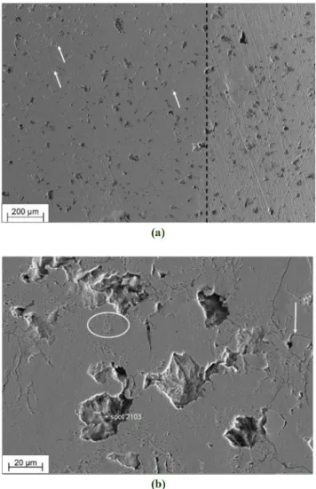
3.4.1 Cast iron cylinder liner
The cast iron microstructure (Figure 10) consists of vermicular graphite withfine lamellar pearlite and randomly distributed graphiteflakes without any spheroidal graphite.
The surfaces of the cast iron samples show the highest Figure 5 Rq of the cylinder samples before (left) and after the test (right)
Figure 6 Rq of the piston ring samples before (left) and after the test (right)
density of large break-outs of material of all the surfaces investigated here. The dashed line inFigure 10(a)divides the wear zone (left of the line) and the unworn surface (right). As break-outs already existed in the initial condition (i.e. after honing), they are not a result of the tribological testing. Only the density of cracks was observed to increase in the tribologically stressed part of the surface.Figure 10(b) shows typical pits in the worn surface of the cast iron with a diameter of about 25 mm and a depth of approximately 1 mm. Lateral distances between these break-outs in the tribosurface range from 30 to 100mm. In between the pits, the worn surface appears to be smooth but is pervaded by long branched cracks, which mainly propagate along the cementite structures and eventually lead to the observed shallow break-outs of material.
The pre-existing deeper pits get slightly wider due to wear of their edges in the tribocontact, but such deep pits are not included in the determination of the Rq values. Only shallow pits and cracks contribute to the surface roughness measured with 3D microscopy [shallow pits are indicated by white
arrows inFigure 10(a)]. The scanning electron microscopy (SEM) pictures show that a smoothening of the pearlitic matrix phase takes place, as the honing marks are completely abraded. This abrasion of the pearlitic matrix constitutes the wear volume measured with the RIC method. A minor orange-peel-like roughening [encircled region inFigure 10 (b)] can be observed in the neighbourhood of the cracks, which are most likely caused by sets of cementite plates oriented perpendicular to the tribosurface [see white arrow in Figure 10(b)]. A formation of grooves or flakes cannot be observed and only shallow pits with a depth of less than 5mm evolve in the tribocontact region where fragments of pearlite grains are abraded.
3.4.2 Plasma transferred wire arc-coated cylinder liner
The plasma sprayed Fe-coating shows a structure which is characteristic for thermal sprayed coatings consisting of solidified splats (Figure 11), including pores and intersplat thin oxide layers (Rabiei et al., 1999). The unworn surface in Figure 8 Cylinder liner steady-state wear rate for different material
pairings (measured with RIC)
Figure 9 Comparison of the total wear of the cylinder samples at the end of the test measured with the RIC and DST methods
Figure 10 (a) SEM image of the cast iron cylinder liner surface with a dashed line dividing the wear track (left) and the unworn surface (right) (white arrows indicate shallow pits) and (b) detail of some orange-peel- like roughening (encircled region), pits and cracks (white arrow) in the worn surface
Figure 7 Cylinder liner running in for different material pairings (measured with RIC)
Figure 11(b)shows that some splats were delaminated by the honing process, but no splat fractures or fragmentations were observed on the originally honed surface or within the worn surface [Figure 11(a)]. The lateral dimensions of the delamination pits of 20-40mm are comparable to those in cast iron, but the average distances between them are smaller. The splats observed in the tribocontact shown in Figure 11(a) exhibit similar lateral dimensions as in the unworn surface.
Therefore, the SEM pictures give no evidence that splats are formed or abraded during the wear process. The micropores, which can be seen inFigure 11(a)(white arrows), do not seem to initiate cracks and no crack network encircles the larger pits [Figure 11(b)] like in the cast iron tribosurface.Figure 11(a)
shows that the honing structure–the one with lowest Rq values of all samples–was still partly observable after the tribometer test. In fact, the wear depth is so low compared to the depth of the honing marks that the edges of the tribocontact are not clearly discernible. This indicates a clearly higher wear resistance of the Fe-matrix compared to the cast iron matrix (Hahn et al., 2009) and is in good agreement with the low amount of wear measured with the RIC. Despite the observed smoothing of the honing structure, the Rq values increase due to the tribological process and reach equal or even slightly higher values than the cast iron tribosurface. This can be attributed to more pores of the Fe-based coating being exposed during the wear process (Figure 11).
Figure 11 (a) SEM image of the wear track (left) and an unworn surface region (right) of the PTWA-coated cylinder liner surface (the white arrows indicate pre-existing pores in both areas) and (b) detail of the tribosurface showing a pre-existing pit and some micropores
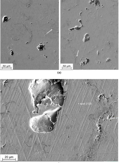
3.4.3 AlSi cylinder liner
The dashed line inFigure 12(a)divides the wear zone (left of the line) and the unworn surface (right). On the initial honed surface, break-outs with lateral dimensions up to 30mm can be observed [white arrow inFigure 12(a)]. On the worn surface of the AlSi cylinders [Figure 12(a), left], numerous small additional break-outs were produced. The break-outs lead to a seemingly rough appearance of the AlSi worn surfaces in the SEM pictures. However, the honing structure was completely worn in the Al-matrix leading to lower Rq values of AlSi after the experiments compared to the initial surface. An image of the wear zone with higher magnification [Figure 12(b)] shows that microstructural phases can be clearly distinguished by their morphology and brightness with SEM. The size of the pits is similar to the lateral size of the hard phases and the pits can therefore be regarded as break-outs of the Si particles and fragments of the intermetallic phase. In between these break- outs, the worn surface of the Al-matrix appears to be much smoother compared to cast iron (Figure 10), because the latter is pervaded by a crack network accompanied by some orange-
peel-like roughening. Some Si particles have only partly detached from the surface, but are cracked and show the status right before being removed from the surface [Figure 12(b)].
The more ductile eutectic phase (white in the SEM image) shows hardly any cracks, presumably because some small cracked debris have already detached from the surface. The depths of these small pits are about 0.5mm and partly up to 2.5mm for Si particles and the intermetallic phase. Wear debris that might have formed from these fragments did not create any wear grooves in the tribocontact.Figure 12(a)shows that the Al-matrix is smoothly worn without indications of grooves caused by wear debris. We regard these results as an indication for afine fragmentation of all hard phases pulled out during the sliding motion, followed by an effective transportation out of the contact zone by the lubricant (Figure 12).
4. Discussion
To rank material combination for the piston ring and the cylinder liner with the optimal tribological performance in TDC pressure conditions, the following parameters have to be considered: material microstructure, surface topography, the lubricant and the different operating conditions ranging from boundary to hydrodynamic lubrication. Tribometer testing enables a separation of these parameters and to focus on the individual influence of single tribological parameters, leading to clearer results (Johanssonet al., 2011). Naturally, the focus on specific aspects limits the extent to which extrapolation is possible. This paper concentrates on mechanical effects and identification of key parameters, determining steady-state wear rates, which can be one factor for making lifetime prognoses.
But for a material selection, the results in the present paper should be interpreted in conjunction withfindings in literature focusing on other influencing factors – for example, the experimental simulation of tribochemical effects due to afired engine (Morina et al., 2011), contaminations from fuel (De Silva et al., 2011; Lenauer et al., 2015), effects of various lubricants (Truhanet al., 2005a) or soot (Truhanet al., 2005b).
Even reducing the possible influences to just the mechanical aspects, numerous strategies exist in literature regarding experimental simulation of engine conditions in tribometers.
Certain choices of tribometer parameters, of how to accurately reflect engine conditions, have to be made (Lee and Chittenden, 2010).Johanssonet al.(2011), for example, based their experimental simulation on the Hersey parameter, which contains information about the lubrication conditions. In this manuscript, a similar approach is chosen, where the lubrication regime is calculated via the l value (the minimum oil film thickness divided by reduced roughness). In addition, the contact pressure–calculated with the Hertzian contact model– is compared to contact pressures in the engine piston ring– cylinder liner contact (similar toTruhanet al., 2005a).
When comparing tribometer results and wear behaviour in real engines, it has to be mentioned that a constant normal load is applied in the tribometer test, whereas the piston ring and cylinder liner contact at TDC in a real engine is subject to cyclic loading conditions as the combustion pressure is present only for every fourth stroke of the piston ring over TDC position.
In this work, the bore diameter of the cylinder types varies from 79 mm to 86 mm. For the tribometer tests, the piston ring Figure 12 (a) SEM image of the AlSi cylinder liner surface with a
dashed line dividing the wear track (left) and the unworn surface (right) (white arrow points out a typical break-out with lateral dimensions up to 30mm) and (b) detail of the worn surface showing intermetallic phases, Si fragments and eutectic phases
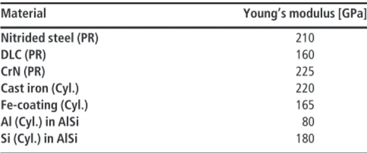
samples are bent to a curvature radius that is approximately 3 per cent smaller than the cylinder liner radius. This alignment avoids contact zones at the edges of the cut cylinder samples and ensures a contact area in the centre. The piston rings have a barrel-shaped sliding surface. The radius of curvature for this convex barrel shape is approximately 14 mm for all piston ring types. These particular sample geometries, as well as the Young’s Moduli (Table IV) and the normal load of 100 N in the tribometer, were used to calculate the Hertzian contact for each material combination at the start of the tribotest. The contact pressures for the tested pairings at test start lie between 245 and 370 MPa (Table V), which is in the range given by Mishraet al.(2008), whereas other values given in literature are lower.
The Young’s Moduli of the cylinder and piston ring materials were determined by nanoindentation measurements (Table IV). For the AlSi cylinders, the Young’s Moduli of the aluminium matrix and of the silicon particles were measured separately. Consequently, a rather wide range of Hertzian contact stress is given for the material pairings AlSi-nSt and AlSi-DLC due to the big difference of the Young’s Moduli of the aluminium matrix and the silicon particles. The lower contact stress represents a contact between the Al matrix and the piston ring and the higher value represents a contact between a Si particle and the piston ring. It can be assumed that the Hertzian stresses of the contact between AlSi cylinders and the corresponding piston ring lie within the given ranges.
The calculated Hertzian stresses were used to compare the macroscopic loading conditions in the current experimental setup to others in literature, as well as to real systems, but not to characterize the effectively acting stress tensors beneath the tribocontact. The Hertzian contact stress does not take into account material-specific differences in the surface topography.
Due to the wear process, the piston ring digs into the cylinder liner specimen and the contact geometries change. Thus, the Hertzian contact pressures at the end of the test are estimated as well, depending on thefinal depth of the wear scar and the
resulting change of the contact area geometry. It can be seen that the small wear depths for the cast iron and Fe-coated cylinders do not influence the macroscopic contact pressures.
The greater wear depths on the AlSi cylinder, however, lead to a smaller Hertzian pressure at test end compared to the situation at test start (Table V).
Though the Hertzian contact stresses are useful for comparisons to the real contact situation in the engine, wear is not necessarily directly linked to the contact stress, as the material response to the applied stress tensor can be dominated by inelastic mechanisms, such as crack propagation and plastic flow. To ensure that tribometer conditions reproduce the wear mechanisms in the engine, the minimumfilm thickness and the resulting effective lubrication condition are calculated.
According toHamrock and Dowson (1981), the minimum film thickness of the lubricant in the contact at the start and the end of the wear experiments can be calculated by the following equation:
h0¼3:63r0 Uh0
E0r0
0:68
aE0
ð Þ0:49 W E0r02
0:073
1e0:68k
ð Þ
h0= minimumfilm thickness (m);
U= entraining surface velocity (m/s);
h0= is the dynamic viscosity at atmospheric pressure of the lubricant (Pa·s);
E0= reduced Young’s modulus (Pa);
r0= reduced radius of curvature (m);
a= pressure-viscosity coefficient (m2/N);
W= contact load (N); and
k= ellipticity parameter defined as:k = a/b, whereais the semi- axis of the contact ellipse in the transverse direction (m) andbis the semi-axis in the direction of motion (m).
For the sliding motion between the contact partners in the presented work, the entraining velocity U was set to the maximum piston ring velocity in the middle of the stroke of the reciprocating movement in the SRV tribometer. Thus, the calculatedfilm thickness is the upper limit for the tribocontact.
The lubrication regime can be determined via thel value, which is defined by the ratiol = h0/Rq0of the minimumfilm thicknessh0to the reduced roughnessRq0.
Rq0has to be calculated using RMS roughness valuesRq1and Rq2of the piston ring and cylinder liner, respectively. TheRq¨
values parallel to sliding direction for the different material component combinations are given inTable VI, as well as the corresponding l values. Both parameters are given for Table IV Young’s moduli of piston ring (PR) and cylinder liner (Cyl.)
materials
Material Young’s modulus [GPa]
Nitrided steel (PR) 210
DLC (PR) 160
CrN (PR) 225
Cast iron (Cyl.) 220
Fe-coating (Cyl.) 165
Al (Cyl.) in AlSi 80
Si (Cyl.) in AlSi 180
Table V Hertzian contact pressure for piston ring and cylinder liner material pairings at test start
Material pairing Hertzian contact pressure at test start (MPa) Hertzian contact pressure at test end (MPa)
Cast iron–nSt 370 370
Fe-coating–nSt 340 340
Fe-coating–CrN 345 345
AlSi–nSt 260-360 150-190
AlSi–DLC 245-325 185-230
the initial surfaces before the test and the worn surfaces after the experiment. According toTaylor (1993),l values below 1 indicate boundary lubrication, whereas values between 1 and 3 imply mixed lubrication. Ifl is greater than 3, hydrodynamic conditions are expected.
Thel values are significantly smaller than 1 for all loading conditions and material combinations included here (Table VI), indicating boundary lubrication conditions for all tribometer tests. Therefore, the friction and wear behaviour is mainly influenced by the metal-metal contact and the tribofilm is formed between the friction partners. With an increasing number of asperity contacts, which depend on the tribological loading conditions, the material structure will dominate the wear process.
Note that Hertzian contact calculations do not take lubricant films into account, but as the l values refer to boundary lubrication conditions, the Hertzian contact pressures serve as good estimation for the real contact pressures.
According to the estimated lubrication regime (Table VI) and the contact pressures (Table V) of the conducted tests, it can be concluded that the contact situations were similar to boundary lubrication at TDC during the power stroke and that the tribometer test parameters (Table II) are adequate to model the tribological conditions of the TDC, where the highest wear rates of the piston ring cylinder liner contact occur.
In the following, the influence of the material pairing, surface roughness and contact pressure on the friction and wear behaviour is discussed.
No correlation was found between the COF and the reduced roughnessRq0. The initial reduced roughness for the pairings with iron-based liners varies in the range from 0.10 mm to 0.19mm, whereas the COF is approximately 0.12 for all these combinations. Furthermore, the initial Rq0 for the AlSi combinations is approximately 0.15mm and in the range of the other pairings, whereas the COF is approximately 0.17 and therefore significantly higher compared to other pairings. It can be concluded that the initialRq0has less influence on the COF than the combined effect of parameters, such as material composition, the presence of wear particles and the related wear mechanisms (such as fatigue wear, abrasive wear and selective cracking of hard phases).
The difference of theRq0roughness values for AlSi and the other cylinder samples is within a small range and is unlikely to cause such large differences in the wear values. Therefore, the material characteristics can be regarded as the most influential factor for the wear behaviour in the present tests.
The characterisation of the worn surfaces with SEM gives some insight into the prevailing wear mechanisms, which are described in detail. The cast iron structure shows a pronounced crack network in the worn surface, which was also described by
Terheci (2000), who studied surface fatigue wear. The graphite lamellas and the pearlitic structure favour crack initiation and propagation along their interfaces. Some cracks already existed in the initial condition of the sample prior to the tribotest, but the cyclic tensile and compressive stresses in the cylinder liner surface executed by the loading and unloading of the ring movement promote the growth of surface fatigue cracks. In literature, the wear behaviour of cast iron was described e.g. by Prasad (2007)for cast iron with different amounts of pearlite and different morphologies of graphite, as well as for different lubricants. He described the cracking tendency of the graphite/
ferrite interface and of the pearlitic matrix in cast iron, which eventually leads to chip formation and break-outs, especially for pressures above 10 MPa.
The wear behaviour of the PTWA Fe-coating seems to be determined mainly by its lattice structure within the coating.
The iron-based matrix seems to have a high resistance against wear. The initial honing structure, though being the smoothest, is partly still preserved after the test. This suggests constant wear by atom-by-atom removal–or small clusters of atoms.
The initial structure of the PTWA coating does not seem to influence the wear process in the conditions studied here, as the bonding structures do not seem to be vulnerable and no difference in wear depth evolves. The PTWA coating process creates splat structures, which solidify onto each other and result in bonding structures characterized by numerous micropores strung together. The PTWA splats delaminate due to shear stresses acting during machining processes and result in some rather shallow and wide pits (Hahn et al., 2009).
Neither the amount nor the size of these pits increase within the wear track. Only a small number of micropores (which can be found in the carbon-enriched layers at the interfaces of former splats) seem to open up due to wear in the tribosurface, which matches the low RIC wear rates for the PTWA material.
In the AlSi material, hard and less ductile phases or particles are present in the surface zone. These more brittle phases break due to the tensile stresses and are removed from the worn surface with the lubricant. No wear grooves were observed in the Al matrix, which shows that the matrix wears continuously. Any wear debris formed by fragments of hard phases are supposed to be effectively transported out of the tribocontact by the lubricant.
Adhesive wear effects are considered unlikely, as Lasa and Rodriguez-Ibabe (2002)found particle sizes of typically 50mm for adhesive wear, which would cause visible and deep grooves not observed on our worn surfaces. No cracks were observed in the Al-matrix despite the observed fragmentation of Si-particles and neither the matrix nor the Si-particles stuck out of the worn surface. In literature, several different characteristics of material behaviour are observed and described for a variety of Al-alloys tested in slightly different conditions.Dienwiebelet al.(2007) Table VI Reduced roughnessRq0andlratio for different material pairings calculated for initial surfaces and worn surfaces
Material pairing Rq0(mm) of initial surfaces Rq0(mm) of worn surface l() for initial surfaces l() for worn surfaces
CI–nSt 0.19 0.15 0.15 0.18
Fe-c–nSt 0.12 0.16 0.23 0.18
Fe-c–CrN 0.10 0.12 0.27 0.23
AlSi–nSt 0.16 0.12 0.18 0.24
AlSi–DLC 0.15 0.12 0.19 0.24
observed the formation of a mechanical tribolayer andLasa and Rodriguez-Ibabe (2002) described largely different wear mechanisms for the same alloy depending on their heat treatment and sliding velocity during the test. Here, in our setup, we observed two mechanisms for AlSi occurring simultaneously:
fragmentation and break-out of hard particles, leading to pits and wear of the Al-matrix. No indication for adhesive wear was found. Plastic deformation of the top-most layer, in addition to the fragmentation and the crack growth, cannot be excluded, and a mechanical tribolayer formed by incorporated wear debris such as those described byDienwiebelet al.(2007)was not observed in the SEM pictures, where we saw a rather smooth surface between break-out pits of the large Si-particles.
The high number of pits in the AlSi material caused by the large amount of wear debris generated during the tribo-process explains the high wear rates and the high total wear volumes The differences in wear of the AlSi cylinders against nSt or DLC can be explained by the nature of the DLC coating, which shows low resistance against shear and thus easily forms a protective tribofilm on the counterpart, thus reducing wear (Liu and Meletis, 1997;Erdemir, 2001;Ronkainenet al., 2001).
In short, the SEM pictures of the tribosurface contain clear indications for fatigue behaviour in the case of cast iron and for constant abrasive wear by tiny wear debris for the AlSi combinations, both highly non-elastic material behaviours, which cannot be described by Hertz.
Referring to literature, the measured cylinder liner wear rates are roughly in the range expected for real engine operation.
Truhan et al. (2005b) cited wear rates of cylinder liners between 2 and 20 nm/h, which were measured with radioactive tracer methods. The wear rates for cast iron liners and Fe- coated liners given in the present publication are around 13 and 5 nm/h, respectively, which puts them in this range. They are in accordance with expected wear rates given by manufacturers of 10 mm in 1,000 h (Kumaret al., 2000). Together with the analysis of the loading and lubrication conditions, this leads us to conclude the tribometer results approximate the real engine wear behaviour at the TDC sufficiently within the lab environment. The AlSi cylinder wear rates in this publication lie in the range of approximately100 nm/h, being significantly higher than the range cited above. However, the chosen loading conditions represent only a certain range of possible engine operating conditions. For example, more moderate loading conditions could be more favourable for the use of AlSi liners.
While the multitude of effects and influences in a real engine cannot realistically be completely replicated in a tribometer environment, the results in this paper shed some light onto one particular aspect of piston ring–cylinder liner tribology: keeping the lubricant constant, the material type of the cylinder liner is the most important factor for the cylinder liner wear mechanisms under these loading conditions, while the piston ring material and the surface roughness play a much smaller role.
These results should be interpreted in conjunction with other results from the authors (such as wear behaviour changes due to oil aging with combustion products [Lenaueret al., 2015] or tribofilm durability [Spilleret al., 2016]) or further literature concerning both tribometer testing and real engine tests, especially regarding longer term effects. Such long-term effects can also eventually have a significant effect on the wear behaviour of the different component materials.
5. Conclusions
Different material combinations for cylinder liner and piston ring tribocontacts were investigated regarding their wear behaviour in the boundary and mixed lubrication regime under sliding reciprocating movement, which is mainly present in the engine at upper TDC during the power stroke. We draw the following conclusions from the results:
The PTWA-coated liners show the least amount of wear and the lowest wear rates. Wear is slightly higher for cast iron cylinders, whereas the highest wear was observed for the AlSi liners. The influence of the piston ring material was observed to be much smaller than the influence of the cylinder liner material and their surface structures.
The material structure and its behaviour under these loading conditions are the most influential parameters for the resulting wear mechanisms.
The cast iron liners showed crack initiation and propagation due to fatigue. In the AlSi material, brittle phases or particles break due to the tensile stresses and the fragments are removed from the contact with the lubricant, whereas the Al matrix is worn homogeneously without showing any grooves. Only the tested PTWA- coated liners show high wear resistance for these conditions, showing homogeneous wear of the matrix phase.
From the investigated material pairings, PTWA cylinder liner and CrN piston ring turned out to be the best combination with respect to the friction and wear behaviour in the tribometer tests representing the tribological conditions of the TDC during the power stroke. These materials are used in real engines to reduce friction (Gangopadhyay, 2017). This study proves that this pairing also shows very good wear behaviour.
References
Bianchi, D., Lenauer, C., Betz, G. and Vernes, A. (2017),“A waveletfiltering method for cumulative gamma spectroscopy used in wear measurements”,Applied Radiation and Isotopes, Vol. 120, doi:10.1016/j.apradiso.2016.11.019.
Bobzin, K., Ernst, F., Zwick, J. and Schlaefer, T. (2007),
“Beschichtung von zylinderlaufflächen moderner PKW- motoren mit niedriglegierten stählen und einem nanokristallinen kompositwerkstoff”, Tribologie und Schmierungstechnik, Vol. 54 No. 2, pp. 11-16.
Cho, S.-W., Choi, S.-M. and Bae, C.-S. (2000),“Frictional modes of barrel shaped piston rings under flooded lubrication”, Tribology International, Vol. 33 No. 8, pp. 545-551, doi:10.1016/S0301-679X(00)00103-1.
Chong, W.W.F., Teodorescu, M. and Vaughan, N.D. (2011),
“Cavitation induced starvation for piston-ring/liner tribological conjunction”, Tribology International, Vol. 44 No. 4, pp. 483-497, available at:http://dx.doi.org/10.1016/j.
triboint.2010.12.008
De Silva, P., Priest, M., Lee, P., Coy, R. and Taylor, R.
(2011), “Tribometer investigation of the frictional response of piston rings when lubricated with the separated phases of lubricant contaminated with the gasoline
engine”, Tribology Letters, Vol. 43 No. 2, pp. 107-120, doi:10.1007/s11249-011-9809-3.
Dienwiebel, M., Pöhlmann, K. and Scherge, M. (2007),
“Origins of the wear resistance of AlSi cylinder bore surfaces studies by surface analytical tools”, Tribology International, Vol. 40 Nos 10/12, pp. 1597-1602, doi: 10.1016/j.
triboint.2007.01.015.
Ditroi, F., Fehsenfeld, P., Khanna, A.S., Konstantinov, I., Mahjunka, I., Racolta, P.M., Sauvage, T. and Thereska, J.
(1997), “The thin layer activation method and its applications in industry”, IAEA Tecdoc, IAEA, Vienna, p. 924.
Ditroi, F., Takács, S., Tárkányi, F., Corniani, E., Smith, R.W., Jech, M. and Wopelka, T. (2012), “Sub-micron wear measurement using activities under the free handling limit”, Journal of Radioanalytical and Nuclear Chemistry, Vol. 292 No. 3, pp. 1147-1152, doi:10.1007/s10967-012-1625-1.
Dwivedi, D.K. (2006),“Wear behaviour of cast hypereutectic Aluminium Silicon alloys”, Materials & Design, Vol. 27 No. 7, pp. 610-616, doi:10.1016/j.matdes.2004.11.029.
Erdemir, A. (2001), “The role of hydrogen in tribological properties of diamond-like carbon films”, Surface and Coatings Technology, Vols 146/147, pp. 292-297, doi:10.1016/S0257-8972(01)01417-7.
Friedrich, C., Berg, G., Broszeit, E., Rick, F. and Holland, J.
(1997),“PVD Cr N coatings for tribological application on piston rings”,Surface and Coatings Technology, Vol. 97 Nos 1/3, pp. 661-668, doi:10.1016/S0257-8972(97)00335-6.
Gangopadhyay, A. (2017), “A review of automotive engine friction reduction opportunities through technologies related to tribology”, Transactions of the Indian Institute of Metals, Vol. 70 No. 2, pp. 527-535, doi:10.1007/s12666-016-1001-x.
Grün, F., Summer, F., Pondicherry, K.S., Godor, I., Offenbecher, M. and Lainé, E. (2012), “Tribological functionality of Aluminium sliding materials with hard phases under lubricated conditions”, Wear, Vols 298/299 No. 1, pp. 127-134, doi: 10.1016/j.
wear.2012.11.048.
Hahn, M., Theissmann, R., Gleising, B., Dudzinski, W. and Fischer, A. (2009), “Microstructural alterations within thermal spray coatings during highly loaded diesel engine tests”,Wear, Vol. 267 Nos 5/8, pp. 916-924, doi:10.1016/j.
wear.2008.12.109.
Hamrock, B.J. and Dowson, D. (1981), Ball Bearing Lubrication: The Elastohydrodynamics of Elliptical Contacts, John Wiley & Sons, Hoboken, NJ.
Hersey, M.D. (1966), Theory and Research in Lubrication:
Foundation for Future Developments, John Wiley & Sons, Hoboken, NJ.
Jech, M. (2012),“Wear measurement at nanoscopic scale by means of radioactive isotopes”, Ph.D. Thesis, Vienna University of Technology.
Johansson, S., Frennfelt, C., Killinger, A., Nilsson, P.H., Ohlsson, R. and Rosén, B.G. (2011),“Frictional evaluation of thermally sprayed coatings applied on the cylinder liner of a heavy duty diesel engine: pilot tribometer analysis and full scale engine test”, Wear, Vol. 273 No. 1, pp. 82-92, doi:10.1016/j.wear.2011.06.021.
Johansson, S., Nilsson, P.H., Ohlsson, R. and Rosén, B.-G.
(2011),“Experimental friction evaluation of cylinder liner/
piston ring contact”,Wear, Vol. 271 Nos 3/4, pp. 625-633, doi:10.1016/j.wear.2010.08.028.
Kumar, R., Kumar, S., Prakash, B. and Sethuramiah, A.
(2000),“Assessment of engine liner wear from bearing area curves”,Wear, Vol. 239 No. 2, pp. 282-286.
Lasa, L. and Rodriguez-Ibabe, J.M. (2002), “Effect of composition and processing route on the wear behaviour of Al-Si alloys”,Scripta Materialia, Vol. 46 No. 6, pp. 477-481, doi:10.1016/S1359-6462(02)00020-9.
Lee, P.M. and Chittenden, R.J. (2010),“Consideration of test parameters in reciprocating tribometers used to replicate ring-on-liner contact”, Tribology Letters, Vol. 39 No. 1, pp. 81-89, doi:10.1007/s11249-010-9590-8.
Lenauer, C., Tomastik, C., Wopelka, T. and Jech, M. (2015),
“Piston ring wear and cylinder liner tribofilm in tribotests with lubricants artificially altered with ethanol combustion products”, Tribology International, Vol. 82, pp. 415-422, doi:10.1016/j.triboint.2014.04.034.
Liu, Y. and Meletis, E.I. (1997),“Evidence of graphitization of diamond-like carbon films during sliding wear”, Journal of Materials Science, Vol. 32 No. 13, pp. 3491-3495, doi:10.1023/A:1018641304944.
Mishra, P.C., Balakrishnan, S. and Rahnejat, H. (2008),
“Tribology of compression ring-to-cylinder contact at reversal”,Proceedings of the Institution of Mechanical Engineers, Part J: Journal of Engineering Tribology, Vol. 222 No. 7, pp. 815-826, doi:10.1243/13506501JET410.
Morina, A., Lee, P.M., Priest, M. and Neville, A. (2011),
“Challenges of simulating ‘fired engine’ ring-liner oil additive/surface interactions in ring-liner bench tribometer”, Tribology - Materials, Surfaces & Interfaces, Vol. 5 No. 1, pp. 25-33, doi:10.1179/1751584X11Y.0000000003.
Morris, N., Rahmani, R., Rahnejat, H., King, P.D.D. and Fitzsimons, B. (2013),“Tribology of piston compression ring conjunction under transient thermal mixed regime of lubrication”, Tribology International, Vol. 59, pp. 248-258, available at:http://dx.doi.org/10.1016/j.triboint.2012.09.002 Nicholls, M.A., Norton, P.R., Bancroft, G.M., Kasrai, M., De
Stasio, G. and Wiese, L.M. (2005), “Spatially resolved nanoscale chemical and mechanical characterization of ZDDP antiwear films on aluminum-silicon alloys under cylinder/bore wear conditions”, Tribology Letters, Vol. 18 No. 3, pp. 261-278.
Pereira, G., Lachenwitzer, A., Nicholls, M.A., Kasrai, M., Norton, P.R. and De Stasio, G. (2005), “Chemical characterization and nanomechanical properties of antiwear films fabricated from ZDDP on a near hypereutectic Al-Si alloy”,Tribology Letters, Vol. 18 No. 4, pp. 411-427.
Prasad, B.K. (2007), “Sliding wear response of cast iron as influenced by microstructural features and test condition”, Materials Science and Engineering A, Vol. 456 Nos 1/2, pp. 373-385, doi:10.1016/j.msea.2006.12.009.
Priest, M. and Taylor, C.M. (2000), “Automobile engine tribology - approaching the surface”,Wear, Vol. 241 No. 2, pp. 193-203.
Priest, M., Dowson, D. and Taylor, C.M. (1999),“Predictive wear modelling of lubricated piston rings in a diesel engine”, Wear, Vol. 231 No. 1, pp. 89-101.
Rabiei, A., Mumm, D., Hutchinson, J., Schweinfest, R., Rühle, M. and Evans, A. (1999),“Microstructure, deformation and
cracking characteristics of thermal spray ferrous coatings”, Materials Science and Engineering: A, Vol. 269 Nos 1/2, pp. 152-165, doi:10.1016/S0921-5093(99)00132-X.
Ronkainen, H., Varjus, S., Koskinen, J. and Holmberg, K. (2001),
“Differentiating the tribological performance of hydrogenated and hydrogen-free DLC coatings”,Wear, Vol. 249 Nos 3/4, pp.
260-266, doi:10.1016/S0043-1648(01)00558-0.
Spiller, S., Lenauer, C., Wopelka, T. and Jech, M. (2016)
“Real time durability of tribofilms in the piston ring–cylinder liner contact”, Tribology International. doi: 10.1016/j.
triboint.2016.12.002.
Takacs, S., Ditroi, F. and Tarkanyi, F. (2007), “Homogeneous near surface activity distribution by double energy activation for TLA”, Nuclear Inst.and Methods in Physics Research, B, Vol. 263 No. 1, pp. 140-143.
Taylor, C.M. (1993), Engine Tribology, Elsevier, New York, NY.
Taylor, C.M. (1998), “Automobile engine tribology–design considerations for efficiency and durability”,Wear, Vol. 221 No. 1, pp. 1-8.
Terheci, M. (2000),“Microscopic investigation on the origin of wear by surface fatigue in dry sliding”, Materials Characterization, Vol. 45 No. 1, pp. 1-15, doi: 10.1016/
S1044-5803(00)00045-0.
Truhan, J.J., Qu, J. and Blau, P.J. (2005a), “A rig test to measure friction and wear of heavy duty diesel engine piston
rings and cylinder liners using realistic lubricants”,Tribology International, Vol. 38 No. 3, pp. 211-218, doi: 10.1016/j.
triboint.2004.08.003.
Truhan, J.J., Qu, J. and Blau, P.J. (2005b), “The effect of lubricating oil condition on the friction and wear of piston ring and cylinder liner materials in a reciprocating bench test”, Wear, Vol. 259 Nos 7/12, pp. 1048-1055, doi:10.1016/j.wear.2005.01.025.
Tung, S.C. and McMillan, M.L. (2004), “Automotive tribology overview of current advances and challenges for the future”,Tribology International, Vol. 37 No. 7, pp. 517-536, doi:10.1016/j.triboint.2004.01.013.
Tung, S.C., Gao, H. and Tung, S.C., G.H. (2003),
“Tribological characteristics and surface interaction between piston ring coatings and a blend of energy-conserving oils and ethanol fuels”,Wear, Vol. 255 Nos 7/12, pp. 1276-1285, doi:10.1016/S0043-1648(03)00240-0.
Vorlaufer, G., Jech, M., Boehm, J. and Eder, S. (2010),
“Spatially resolved measurement of sub-micrometre change in surface topography using confocal white light microscopy and image registration techniques”,SPIE Photonics Europe Conference,Brussels, pp. 7718-7719.
Corresponding author
Thomas Wopelka can be contacted at: thomas.wopelka@
ac2t.at
For instructions on how to order reprints of this article, please visit our website:
www.emeraldgrouppublishing.com/licensing/reprints.htm Or contact us for further details:permissions@emeraldinsight.com