This is an open-access article distributed under the terms of the Creative Commons Attribution-NonCommercial 4.0 International License (https://creativecommons.org/licenses/by-nc/4.0/), which permits unrestricted use, distribution, and reproduction in any medium for non-commercial purposes, provided the original author and source are credited, a link to the CC License is provided, and changes – if any – are indicated.
1. Introduction
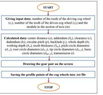
A certain computer program was developed for mak- ing the CAD models [1–6] of the basic toothed gear pairs. Input values of the program are the number of
teeth (z1 and z2)and the module (m) of the driving and driven cog wheels (Fig. 1).
Based on the input parameters, the program cal- culates the further parameters of the gear pairs and it draws the cog wheels on the screen. It saves the profi le points of the cog wheel in .txt fi le, which can be im- ported in SolidWorks design software. After all these CAD models of the given gear pairs can be made.
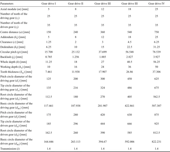
Table 1 contains those parameters of the gear pairs which were designed by us.
During designing the numbers of the teeth of the cog wheels on the driving and the driven gears were chosen equal but we enhanced the value of the module (Table 1).
2. Making the mesh of FEM
For the analysis of the contact points, Ansys R18.0 FEM software was used. In the tooth contact zone, 0.15 frictional factor was applied. During the CAD modelling of the cog wheels, between the root circle diameter and the inner diameters of the bore, 15 mm thickness was applied in the case of every cog wheel.
The tooth length of the cog wheels was chosen to be 40 mm each.
ANALYSIS OF THE NORMAL TENSION VALUES IN THE CONTACT ZONE AND ON THE FILLETS OF THE BASIC TOOTHED GEAR PAIRS AS A FUNCTION OF THE CHANGE OF THE MODULE
S. BODZÁS
Department of Mechanical Engineering, University of Debrecen, H-4028 Debrecen, Ótemető u. 2–4, Hungary E-mail: bodzassandor@eng.unideb.hu
In our publication, more than one basic toothed gear pairs have been designed and modelled. Normal tension dispersions – appear- ing in the contact zone of the drive pair – and their measure on contact tooth surfaces have been analyzed by the effect of a given moment load. During designing the numbers of the teeth of the gear pairs have been chosen equal, but the modules of the pairs have been different. We analyze how normal tension values form on the tooth surfaces of the gears in the contact zone of the tooth and on their root zone as a function of the change of the module in the case of the same meshing method, loads and boundary conditions.
Keywords: basic toothing, fi nite element method (FEM), normal tension, module
Fig. 1. The principle of the operation of the program
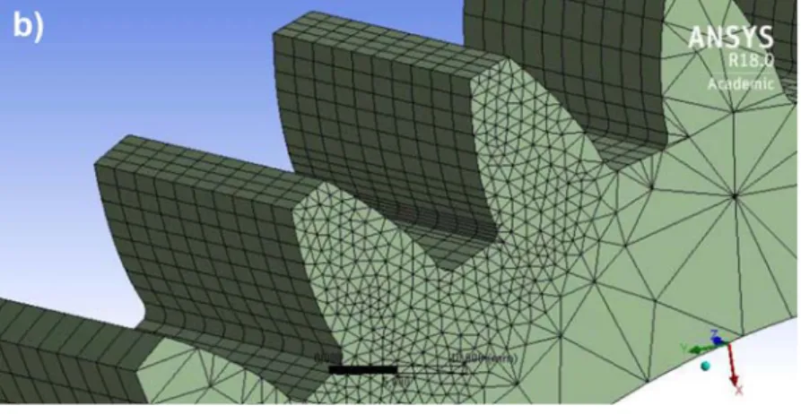
During the calculations tetrahedron meshing was applied on the face surfaces, while tooth lengths were divided into 10 equal parts [5, 9]. The density of the meshing was automatic outside the tooth contact zone [5, 9]. Inside the tooth contact zone 1 mm density meshing was applied (Fig. 2).
3. Setting the loads and boundary conditions
During the analysis, the material of the drive pairs was structural steel (Table 2). The driving cog wheel (z1 = 25) was loaded by 40 Nm torque (Fig. 3).
Table 1. The parameters of the designed drive pairs
Parameters Gear drive I Gear drive II Gear drive III Gear drive III Gear drive IV
Axial module (m) [mm] 5 8 12 18 25
Number of tooth of the
driving gear (z1) 25 25 25 25 25
Number of tooth of the
driven gear (z2) 35 35 35 35 35
Centre distance (a) [mm] 150 240 360 540 750
Addendum (ha) [mm] 5 8 12 18 25
Clearance (c) [mm] 1.25 2 3 4.5 6.25
Dedendum (hf) [mm] 6.25 10 15 22.5 31.25
Circular pitch (p) [mm] 15.708 25.132 37.699 56.548 78.539
Backlash (js) [mm] 0.785 1.256 1.885 2.827 3.927
Whole depth (h) [mm] 11.25 18 27 40.5 56.25
Working depth (hw) [mm] 10 16 24 36 50
Tooth thickness (Sax) [mm] 7.461 11.938 17.907 26.86 37.306
Pitch circle diameter of the
driving gear (d1) [mm] 125 200 300 450 625
Tip circle diameter of the
driving gear (da1) [mm] 135 216 324 486 675
Root circle diameter of the
driving gear (df1) [mm] 112.5 180 270 405 562.5
Basic circle diameter of the
driving gear (dak1) [mm] 117.461 187.938 281.907 422.861 587.307
Pitch circle diameter of the
driven gear (d2) [mm] 175 280 420 630 875
Tip circle diameter of the
driven gear (da2) [mm] 185 296 444 666 925
Root circle diameter of the
driven gear (df2) [mm] 162.5 260 390 585 812.5
Basic circle diameter of the
driven gear (dak2) [mm] 164.446 263.113 394.67 592.006 822.231
Transmission (i) 1.4 1.4 1.4 1.4 1.4
Fig. 2. Application of the mesh of FEM
Five degrees of freedom of the driving cog wheel were fi xed. Only the rotational movement around the rotational shaft was allowed. In the case of the driven cog wheel fi xed support was applied (Fig. 3) [5, 7–9].
4. Normal tension analyses in the contact zone
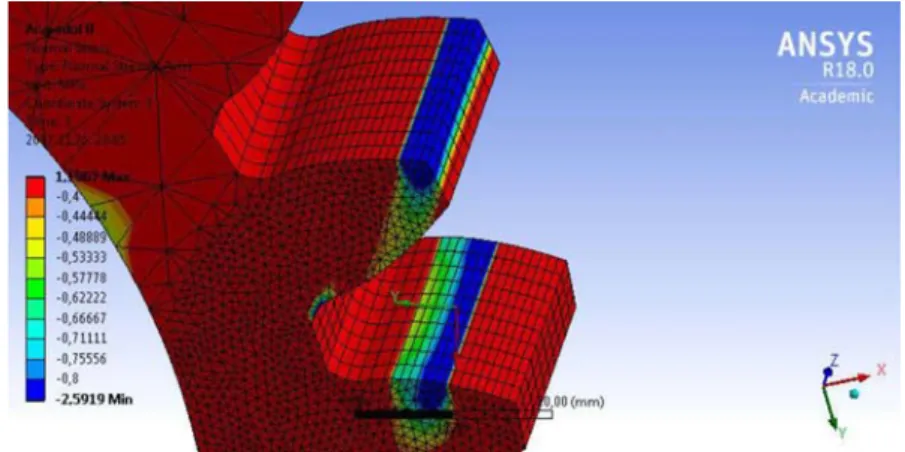
Figure 4 shows normal tension dispersions – on the driving gear contact tooth surfaces – which are the Table 2. Parameters of the material
Density 7850 kg/m3
Yield limit 250 MPa
Ultimate strength 460 MPa
Fig. 2. cont’d
Fig. 3. Setting the loads and boundary conditions
Fig. 4a. In case of 5 mm module (average normal tension on the tooth surface: –1.057 MPa)
Fig. 4b. In case of 8 mm module (average normal tension on the tooth surface: –0.873 MPa)
Fig. 4c. In case of 12 mm module (average normal tension on the tooth surface: –0.642 MPa)
Fig. 4d. In case of 18 mm module (average normal tension on the tooth surface: –0.243 MPa)
Fig. 4e. In case of 25 mm module (average normal tension on the tooth surface: –0.143 MPa).
Normal tension values on the tooth surfaces of the driving cog wheel
effect of the load of 40 Nm torque. Based on Fig. 4, it can be stated that on the tooth surfaces of the driv- ing cog wheels in the contact zone, perpendicular to the tooth surface, the values of the normal tension decrease as a function of enhancing the value of the module.
Figure 5 shows normal tension dispersions – on the contact tooth surfaces of the driving cog wheels – as an effect of the 40 Nm load of torque. Based on Fig. 5, it can be stated that on the tooth surfaces of the driven cog wheels in the contact zone, perpendicular
to the tooth surface, the values of the normal tension decrease as a function of enhancing the value of the module.
5. Normal tension analyses on the fi llet
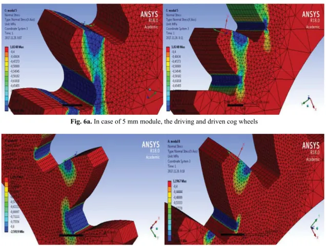
As an effect of the moment, on the fi llet radius of the contact teeth those tension values are formed as shown in Fig. 6. The tension analysis of the fi llet (root of the tooth) is important because of the bending stress and of any accidental tooth break.
Fig. 5a. In case of 5 mm module (average normal tension on the tooth surface: –1.022 MPa)
Fig. 5b. In case of 8 mm module (average normal tension on the tooth surface: –0.834 MPa)
Fig. 5c. In case of 12 mm module (average normal tension on the tooth surface: –0.739 MPa)
Fig. 5d. In case of 18 mm module (average normal tension on the tooth surface: –0.295 MPa)
Fig. 5e. In case of 25 mm module (average normal tension on the tooth surface: –0.136 MPa).
Normal tension values on the tooth surfaces of the driven cog wheel
Fig. 6a. In case of 5 mm module, the driving and driven cog wheels
Fig. 6b. In case of 8 mm module, the driving and driven cog wheels
Figure 6 shows that normal tension values in the fi llet of the contact cog pairs decrease in the way per- pendicular to the surface, as a function of enhancing the module.
6. Summary
A computer program has been developed to ease the designing and modelling of basic toothed gear pairs.
The CAD models of the gear pairs (with equal num-
ber of tooth, but different modules) have been made in Solidworks design software.
The Ansys Finite Element Method (FEM) software has been used to analyze the normal tension values as an effect of the load – on the tooth surfaces of the driv- ing and driven cog wheels. During the analyses, the cog wheels having less number of teeth have been the driv- ing cog wheels. On the face sur faces tetrahedron mesh- ing has been applied, while on the tooth surfaces we ap- plied 10 equally divided mesh – along the tooth length.
Fig. 6c. In case of 12 mm module, the driving and driven cog wheels
Fig. 6d. In case of 18 mm module, the driving and driven cog wheels
Fig. 6e. In case of 25 mm module, the driving and driven cog wheels.
Normal tension values occurring in the fi llet of cog wheels
After setting the load and the boundary condi- tions we got the result that as a function of enhancing the module, on the contact tooth surfaces and fi llets of the driving and driven gear pairs – in the contact zone – normal tension values perpendicular to the surface decrease.
Acknowledgements
This research was supported by the János Bolyai Re- search Scholarship of the Hungarian Academy of Sci- ences.
References
[1] Bodzás S. (2017), Computer aided designing and model- ling of x-zero gear drive. International Review of Applied Sciences and Engineering, 8(1), 93–97.
[2] Dudás I. (2011), Gépgyártástechnológia III., A. Megmun- káló eljárások és szerszámaik, B. Fogazott alkatrészek gyártása és szerszámaik. Műszaki Kiadó, Budapest
[3] Dudás L. (1991), Kapcsolódó felületpárok gyártásgeomet- riai feladatainak megoldása az elérés modell alapján. Kan- didátusi Tézisek, Budapest, TMB, p. 144.
[4] Erney Gy. (1983), Fogaskerekek. Műszaki Könyvkiadó, Budapest, p. 460
[5] Litvin F. L., Fuentes A. (2004), Gear Geometry and Ap- plied Theory. Cambridge University Press, ISBN 978 0 521 81517 8
[6] Terplán Z. (1975), Gépelemek IV. Kézirat, Tankönyv- kiadó, Budapest, p. 220
[7] Páczelt I., Szabó T., Baksa A., A végeselem módszer alap- jai. Értékünk az ember, Humánerőforrás fejlesztési Ope- ratív Program, Miskolci Egyetemi Elektronikus jegyzet [8] Szabó F., Bihari Z., Sarka F. (2006), Termékek, szer ke-
zetek, gépelemek végeselemes modellezés és optimálása.
Szakmérnöki jegyzet, Miskolc
[9] Litvin F. L., Fuentes A., Fan Q., Handschuh R. H. (2002), Computerized Design, Simulation of Meshing, and Con- tact and Stress Analysis of Face-Milled Formate Generat- ed Spiral Bevel Gears. In: Mechanism and Machine Theo- ry, Elsevier, pp. 441–459