THE RHEOLOGY OF ADHESION J. J . Bikerman
I. Introduction 479 II. Application of Adhesives 480
III. Tackiness 4 81
1. Definition 4 81
2. The Hydrodynamic Theory 4 81
3. Limitations of the Theory 4 83
IV. Time of Set 4 85
1. The Mechanism of Setting 4 8^
2. Physical Changes during Setting 48*>
3. Chemical Changes during Setting 4 8?
V. Final Strength 4 88
1. Local Stress and Local Strength 4 88
2. Stresses in a Strained Bond 491
3. Strength and Thinness of Joints 499
4. The True Adhesion 5 01
VI. Summary 5 03
Nomenclature ^03
I. Introduction
As a rule, five layers can be recognized in an adhesive joint. Starting from one of the solids (adherends) they are: first solid, boundary layer, adhesive film, boundary layer, and second solid. If a simple tensile stress is applied to such a joint, normally to the stratification, the weakest of the layers breaks first. In many respects, the knowledge of the layer in which rupture occurs is just as important as that of the value of the break- ing load.
Boundary layers are mentioned at the very start of this article because their importance still is often underestimated. Except for very special systems, such as solids condensed in a high vacuum, the composition of a solid surface is always different from that of the bulk of the solid. In addi- tion to ordinary "dirt" there are oxides on metals, silica-rich layers on glass, etc., and adsorbed gases and vapors on everything. For instance, when a glue is applied to what we call metal surface, it has no contact with any metallic phase.
479
Solid surfaces are also rough or even porous. A simple microscopic ob- servation shows that an adhesive properly applied to paper penetrates into its fibrous structure. Because of the roughness of all solid surfaces, some degree of interpénétration of adhesive and adherends is always present. A striking example of the importance of this interpénétration is afforded by comparison of filter paper and cellophane (that is, regenerated cellulose).
The chemical composition of these two materials is almost identical, but paper is porous (great interpénétration) while cellophane films are unusually smooth (little interpénétration). Almost any adhesive can be used for paper but only few compositions are suitable for cellophane.1 To increase the interpénétration, the solid surfaces often are sandblasted or in another manner roughened before the application of the adhesive.2
Generally, three stages can be recognized in the life history of an adhesive joint. During the first stage the adhesive is applied, during the second it sets, and during the last stage the properties of the system remain, or are supposed to remain, constant.
II. Application of Adhesives
Air occluded by a solid surface or entrapped in its valleys would form a very weak boundary layer. To obtain strong joints this air must be removed. If the adhesive has to displace the air from the surface, it must wet the latter. If the wetting ability is absent (aqueous dextrin solutions and oiled metals are an example), the resulting joints are weak and fail in a boundary layer.
Wetting ability depends on the chemical composition of the two phases (the solid and the liquid) and thus need not be discussed in a book on rheology. However, the rate of displacement of air depends on the rheologi- cal properties of the liquid glue. Thus, a sheet of filter paper was fully wetted by a sodium silicate solution in 70 sec. when the viscosity η of the solution was 2 gm./cm.sec, in 160 sec. when η was 4 gm./cm.sec, in 240 sec. at η = 6, and in 320 sec. at η = 8 (interpolated from the data found in Vail3).
Often the adhesive must displace more than air in the moment of appli- cation. Thus in soldering, the flux chemically changes and dissolves the oxide layer on the metal, and then molten solder displaces the flux.
1 For example, see A. D . McLaren and C. H. Hofrichter, Paper Trade J. 125(19), 96 (1947).
2 For example, see N. J. DeLollis, N. Rucker, and J. E. Wier, Trans. Am. Soc.
Mech. Engrs. 73, 183 (1951).
3 J. G. Vail, "Soluble Silicates," Vol. 2, p. 370. Reinhold, New York, 1952.
III. Tackiness
1. DEFINITION
There is no accepted definition of tack. Here this term means the resist- ance of an adhesive joint to separation as long as the adhesive remains liquid. A definition of liquid as understood here will be given in Section 111,3.
Sometimes a liquid is said to be tacky when it readily forms fibers. The capacity for filamentation depends mainly on the variation of viscosity (or consistency) with elongation, while tack, as defined here, is a function of viscosity (or consistency) itself. Thus these two properties are somewhat related but certainly not identical.
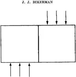
Ε
FIG. 1. A and Ε are adherends, Β and D are boundary layers, C is the adhesive film. The pull is applied in the direction of the arrow. (From Bikerman.4)
2 . T H E HYDRODYNAMIC THEORY
The nature of tack is conveniently discussed for the instance of two circular, plane-parallel, solid plates with an adhesive liquid filling the clearance between the plates (see Fig. I4 and disregard the dotted line marked r). When the plates are pulled apart in the direction of the arrow, the liquid flows toward the axis of the system from the bulges shown in the figure. To maintain this movement in a viscous liquid, a stress has to be continually operative. This is the stress / needed to separate the plates.
Thus, tack is the viscous resistance of a liquid moving in a slit at a rate determined by the rate of separation of the plates. If the plate radius a is much greater than the initial distance h0 between the plates, this move- ment is practically parallel to the plates for almost the whole duration of the experiment; that is, the flow in the direction of the axis (which of course takes place when the plates move apart) may be neglected. For this case and a Newtonian liquid, the relation between stress / and the time t during
4 J. J. Bikerman, / . Colloid Sei. 2, 163 (1947).
which the clearance between the plates increased from ho to hi was derived by Stefan5 as
A more general equation of the same type was deduced by Reynolds.6 A simplified proof of equation (1) was given more recently.4
Equation (1) implies that (a) there is no minimum force (such as molec- ular attraction) which must be overcome to break the bond ; only the prod- uct ft is important; (b) the forces between the solids and the liquid are not involved at all; the rupture is a purely rheological phenomenon; (c) for complete separation (that is, for hi = <χ> ) the product ft is inversely proportional to the square of the initial clearance ; and (d) ft is proportional to the viscosity of the liquid.
Experimental confirmation of equation (1) was started by Stefan him- self. In later experiments some discrepancies were observed, for instance by Green7 and Heidebroek.8 An important reason for these discrepancies was disregard of surface roughness.9 Figure 2 shows the effect of rugosity on the product ft.
Sometimes separation of the two adherends can be accomplished by peeling or stripping rather than by a tensile pull. Both theoretical and experimental studies of peeling are less advanced than those of tensile separation but it appears10 that the time of separation by stripping is
κ is a numerical constant, Ε is the modulus of elasticity of the ribbon which is being stripped off the solid support, η is the (Newtonian) viscosity of the liquid between the ribbon and the support, w and δ are the width and the thickness of the ribbon, F is the applied force, and h0 the initial clearance.
Comparison between equations (1) and (2) shows that t in peeling tests is much shorter than Stefan's t mainly because the former quantity is pro- portional to δ/ho which usually is of the order of one, while the latter is proportional to a/ho2 which usually would exceed 106.
6 M.J. Stefan, Sitzber. Akad. Wiss. Wien, Math.-naturw. KL, Abt. II 69, 713 (1874).
β Ο. Reynolds, Trans. Roy. Soc. 177, 190 (1886).
7 H. Green, Ind. Eng. Chem., Anal. Ed. 13, 632 (1941).
8 E. Heidebroek, Β er. Verhandl. sächs. Akad. Wiss. Leipzig Math.-naturw. Kl. 97(6), 20 (1952).
9 J. J. Bikerman, Trans. Soc. Rheol. 1, 3 (1957).
1 0 J. J. Bikerman and W. Yap, Trans. Soc. Rheol., in press.
( D
hr m s, microns
FIG. 2. Effect of surface roughness on tackiness. Abscissa: mean height of hills on the solid surface. Ordinate: product of stress and time. Paraffin oil between two nickel disks. (From the data of Bikerman.9)
Earlier experiments11"14 on stripping of adhesive tapes and polymer films have been performed on materials which are neither Newtonian liquids nor Hookean solids (see Section IV,2) and therefore cannot be readily treated mathematically. Qualitatively they agree with the main postulate expounded in this section, namely, that tackiness is a rheological phenom- enon not affected by the molecular forces between adherend and adhesive.
3. LIMITATIONS OF THE THEORY
Limitations of equation (1) are many. The theory assumes the viscosity to be a constant. An extension of the treatment to include η variable with velocity gradient could not be found in the literature.
There is only one value of h0 in equation (1). In reality the distance be- tween the plates varies from point to point because of surface roughness.
The effect of rugosity is illustrated in Figure 2.
The centripetal flow of the liquid is directly caused by the pressure differ-
11 R. S. Riwlin, Paint Technol. 9, 215 (1944).
1 2 W. F. Busse, J. M. Lambert, and R. B. Verdery, J. Appl. Phys. 17, 376 (1946).
1 3 J. O. Hendricks, G. F. Lindner, and F. J. Wehmer, Rubber Age (N. Y.) 63, 327 (1948).
14 S. S. Voyutskii, A. I. Shapovalova, and A. P. Pisarenko, Kolloid. Zhur. 19, 274 (1957).
ence between the peripheral and the central portions of the adhesive layer.
The theory assumes that this pressure difference cannot be relieved in any other way. However, if, for instance, air channels remain in the valleys of a solid surface, air—more rapidly than the liquid—will move inward and thus facilitate the separation. If air bubbles can form and grow in the underpressure region at a sufficient speed, they will help to eliminate the pressure difference.15
If the time of separation—that is, t in equation (1)—is very short, the calculated stress / is very large. Indeed it may be greater than the tensile strength of an adherend, in which case breaking of this adherend rather than adhesive flow is the result. Thus gummed kraft paper tape adhering to a glass plate usually can be separated from the plate if slowly pulled away but is torn by a rapid motion.
When the adherends are strong, the adhesive layer gives way also at large stresses (that is, short /). However, the mechanism of the rupture in these instances usually is quite different from that envisaged by Stefan.
No noticeable flow of the adhesive occurs; rather a crack advances in it.
Thus the adhesive breaks down as a solid even if for slow deformation it behaves as a Newtonian liquid. This effect is readily observed for adhesives whose viscosity is greater than, say, 1000 gm./cm.sec. Equation (1) with η = 1000, a = 13.33 cm.2, hi = oo, and h0 = 0.001 cm. a f f o r d s = 1010 gm./cm.sec. Thus a stress of 1010 gm./cm.sec.2 for 1 sec. would be required to cause the Stefan flow of the adhesive. The "solid fracture" takes place at smaller loads and in much shorter times, and the centripetal flow has no chance to materialize.
An intermediate region also exists, namely when the ratio η/t is not so great as to cause a solid fracture nor so small as to give rise to a uniform liquid flow. In this region the adhesive flows not toward the axis of the whole system but toward many points spread all over the adhesive film;
at further separation of the plates, adhesive filaments start from these points. This effect may be crudely accounted for by equation (1), in which a would be the mean half-distance between two nearest filaments; as this distance is small compared with the radius of the plates, the resulting / / is a small fraction of that calculated by Stefan.
At viscosities as high as 1000 gm./cm.sec. the occurrence of a solid frac- ture can be proved by visual inspection of the broken joint because the forces (gravitation, surface tension, etc.) causing further changes in the surface profile are weak in comparison with viscosity forces. At smaller viscosities, the former forces may alter the surface profile of the adhesive during the time elapsing between the rupture and the inspection. Thus only indirect proofs are available for deciding in any given instance whether
1 6 W. H. Banks and C. C. Mill, J. Colloid Sei. 8, 137 (1953).
viscous or elastic forces were more important for the breakdown; that is, whether the adhesive behaved more like a liquid or more like a solid. From experiments on rapidly rolling a cylinder in a shallow layer of a viscous liquid, Voet and Geffken16 concluded that the observations were better accounted for by elastic effects.
It has been mentioned in Section 111,1 that tackiness exists as long as the adhesive is liquid. Now a more detailed definition can be given. Accord- ing to Stefan's equation the breaking stress / greatly depends on the dimen- sion (that is, a) of the system because the whole adhesive film at all times takes part in the flow. At the other extreme, in brittle fracture, breaking stress little depends on the overall dimensions because rupture is a topical phenomenon, i.e., is determined by the properties of one point only (namely the weakest spot in the system) and is not affected by the amount of healthy material around this sick spot. In the intermediate region, the effect of the overall dimensions ranges between these two extremes; presumably, as long as this effect is much greater than for brittle rupture, the adhesive may be called liquid and the resistance to separation may be called tacki- ness.
The usual definitions of tack refer to two operations: the adhesive is first pressed against a solid and then the joint is ruptured. In this section, only the second operation was considered, but its conclusions seem to be applicable to the first as well; as long as the ratio η/t is small, the adhesive will be able to remove the weak boundary layers and the breaking stress will be determined mainly by the viscous flow. When η/t is very large, the boundary layers will not be displaced, there will be no sticking, and, in a separate rupture test, the adhesive would behave as a solid.
All limitations discussed in connection with equation (1) apply also to equation (2). Moreover, this equation implies also that the ribbon is a Hookean solid, is perfectly flat and smooth, and so on.
IV. Time of Set
1. T H E MECHANISM OF SETTING
As soon as an average adhesive is applied, it starts to set, that is its consistency starts to increase. The rate of this increase is very small for pressure-sensitive tapes and is greater for joints which are made to be permanent.
The rate of setting often determines whether the adhesive will or will not be suitable for a particular operation. If the final arrangement of the adherends is performed after the application of the adhesive, the setting time must be long enough to allow this arrangement to be completed. Thus,
1 6 A. Voet and C. F. Geffken, Ind. Eng. Chem. 43, 1614 (1951).
wall papers are pasted to the wall with slow-setting adhesives. On the other hand, in the rapid automatic manufacture of cardboard boxes, the adhesive may be applied hot and set within a second or two.
The change in the rheological properties of the adhesive during setting depends on the chemical composition of the adhesive, but may crudely be described as solidification. There are three main mechanisms of this proc- ess; namely, cooling, drying, and a chemical reaction.
Increase in consistency on cooling is used, for instance, for solders and for the animal glue. In the latter instance it may be classified as sol-gel transformation.
Setting because of the removal of solvent is a very common mechanism.
This removal usually is accomplished by evaporation. To allow a rapid evaporation, the adherends must be porous. In some instances the solvent (or a part of it) is imbibed by the adherends. Thus the time of set of an adhesive between two sheets of paper often depends on the degree of dry- ness of the paper. Also nonporous adherends can imbibe solvents.
Setting of the plaster of Paris is a classical example of solidification caused by a chemical reaction. Many modern adhesives are applied as polymers of a low degree of polymerization and then set because the adhesive further polymerizes in situ; this can be achieved, for instance, by adding a polymer- ization catalyst in the moment of application or by curing the completed joint. In another group (exemplified by the epoxy resins) setting is caused by the cross-linking of a chain polymer with a short bifunctional molecule.
2. PHYSICAL CHANGES DURING SETTING
Increase in the consistency of the adhesive film is accompanied by other physical changes which are of great importance for the fate of the joint.
Setting usually is associated with contraction. If the adherends are in a fixed position—that is, the clearance between them has one definite value—
this contraction can break the bond without any external force. Otherwise, the adherends can follow the volume changes of the adhesive. However it is almost impossible, also in this instance, to avoid creating stresses in both adherends and adhesive during the solidification. When solidification is caused by cooling, the remaining stresses will be smaller the more alike the coefficients of thermal expansion of the adherends and the adhesive;
thus only those metals can be successfully sealed in glass whose heat ex- pansion is equal to that of the glass used. When solidification results from evaporation of the solvent, the stresses may be strong enough to damage the adherends as sometimes happens in gelatin-glass bonds.
The rheological properties of a solid generally depend on the rate of its solidification. This is true also for the adhesive films. Thus, because of the higher heat conductance of copper, a molten adhesive will cool and set
more rapidly between two copper disks than between two lead disks of identical dimensions, and the strength of the adhesive layer should be different in the two instances; no experimental verification of this view could be found in the literature. It has been mentioned in Section IV, 1 that the time of set of the glue may depend on the moisture content of the paper to be glued; hence, also the strength of the final bond may be in- fluenced by this content.
Often the periphery of an adhesive film sets when the center is still liquid. On the subsequent solidification and contraction of the central part, the bond will remain under tension (because the unyielding periphery precludes complete contraction of the film). Nuclei of future destruction can form as a result of this tension. If the adhesive film is of sufficient thickness, it can be seen that its periphery (i.e., the adhesive-air boundary) is concave toward the air. This indicates that the three-phase boundary line between air, adherend, and adhesive could not follow the shrinkage of the adhesive. An estimate of the stresses created by this hindred shrink- age was made by Mylonas.17 In polystyrene-steel bonds rupture is some- times located in a boundary layer near the periphery and within the polystyrene phase in the center of the joint;18 this may be a result of stresses set up during solidification on cooling.
3. CHEMICAL CHANGES DURING SETTING
Chemical changes in adhesive joints are important because they affect the strength of one or several of the five layers of usual joints, enumerated in Section I.
The adhesive—or one of its ingredients—may slowly react with the ad- herends and thus improve or impair their mechanical properties. Thus strongly alkaline adhesives may weaken wood so much that failure occurs in wood at smaller stresses than those needed to break original wood speci- mens. The inverse phenomenon also occurs; that is, the adhesive may be weakened by substances diffusing into it from the adherends.
Chemical reactions in the boundary layers are not uncommon. Thus tin in the customary solders reacts with many metals to form compounds such as FeSn2, Cu6Sn5, etc. Hence, in the majority of soldered joints a boundary between unaltered adherend and unaltered adhesive does not exist; there is a gradual transition from, say, pure copper to copper containing a few crystals of a Cu-Sn compound, to a layer containing less copper and more Cu-Sn compound, etc. Whichever of these layers is the weakest is likely to break first and thus to cause bond failure. When rubber is vulcanized
1 7 See N. A. De Bruyne and R. Houwink, "Adhesion and Adhesives," p. 136.
Elsevier, Amsterdam, 1951.
1 8 H. P. Meissner and G. H. Baldauf, Trans. Am. Soc. Mech. Engrs. 73, 697 (1951).
in contact with brass, CuS forms in the boundary layer; if the rubber contains too much sulfur, the resulting CuS coating is too thick and breaks easily. There is a chemical reaction between enamel and metal during fir- ing.19
Some chemical reactions in the adhesive, which result in its solidification, are mentioned in Section IV,2. Many reactions continue also afterward and often weaken the joint. Thus rubber adhesives can be oxidized by the air and, consequently, lose their flexibility. If crystals of Cu-Sn compounds invade the solder phase, the tensile strength of the solder usually decreases.
Many adhesives become brittle if their moisture loss is too great and re- quire addition of a hygroscopic agent ("humectant") to maintain their resistance to impact. Proteins and some other organic adhesives deteriorate because of attack by microorganisms unless the adhesive composition contains a preservative.
If, after setting, the adhesive film contains many weak spots, its modulus of elasticity is likely to be smaller than that of a flawless film. This modulus can be calculated from the resonance frequency of the joint subjected to ultrasonic vibration.20 By means of such measurements it is possible to separate the chemical from the physical deterioration of bond. If, for in- stance, a joint between aluminum and aluminum is heated and cooled again, the loss in bond strength is less than when an identical heat treat- ment is applied to a steel-steel joint with the same adhesive (a phenol- formaldehyde plus vinyl butyral resin) ; this would be the physical effect since the difference between the thermal expansions of aluminum and resin is smaller than that between steel and resin. On the other hand, temporary deep cooling of joints had a much weaker effect on their strength than a heating of a similar intensity; presumably, heating impaired the strength because of both physical and chemical effects while chemical deterioration was almost absent at low temperatures.
V. Final Strength
1. LOCAL STRESS AND LOCAL STRENGTH
The final strength, /0, of a joint usually is even more important than the tackiness of the adhesive at the application stage. The correct calculation of fo from the experimental results on bond rupture is not simple, and the simple calculations still common in the literature and the industrial appli- cations are inexact or incorrect.
1 9 W. N. Harrison, J. C. Richmond, J. W. Pitts, and S. G. Benner, J. Am. Ceram.
Soc. 35, 113 (1952).
2 0 A. G. H. Dietz, H. N. Bockstruck, and G. Epstein, Am. Soc. Testing Materials, Special Tech. Puhl. No. 138 (1952).
An adhesive joint breaks when and where the local stress exceeds the local strength in the stress direction. The local stress differs from the aver- age stress (arrived at, for instance, by dividing the external force by the area on which it acts) because of three complications.
(a) Often an internal stress acquired during the setting is present in the adhesive film and in the adherends; it has been mentioned in Section IV,2. The local stress then is the sum of this stress and that caused by the external force.
(b) Depending on the geometry of the joint, the stress caused by the external force would vary from point to point even if all the ingredients of the joint were uniform down to molecular dimensions. This macroscopic stress concentration is treated in Section V,2.
(c) There exists also a microscopic or submicroscopic stress concentra- tion at every flaw (such as a crack or a bubble) in a solid. The theory of this effect is extensive,21 and only the simplest equation can be reproduced here.
If a small ellipse is cut out in a large plate and the plate is subjected to tensile stress of the average value po, then the stress at the two apexes of the ellipse is
ρ = po(l + 2a/b), (3) if a and b are the half-axes of the ellipse, respectively normal and parallel
to the stress direction. If the flaw is circular, a = b and ρ = 3p0 ; that is, the highest stress is 3 times the average. If the flaw is a crack perpendicular to the stress direction, a is very much greater than 6, and ρ may, for in- stance, be 1000 times as great as po.
Rupture starts at a point where the local stress (calculated with due regard to the above-mentioned complications) exceeds the local strength.
This point, as a rule, is situated in one of the adherends, in one of the boundary layers, or in the adhesive film. Section V,4 discusses the less probable case of the rupture starting between an adherend and the adhesive.
If the rupture occurs fully in an adherend, it is clear that the breaking stress is a function of the tensile (or shear) strength of the material of the adherend and has no connection with adhesive forces. When paper, card- board, or even wood is the adherend, this kind of rupture is quite common.
The rest of the joints may be classified as "proper" and "improper."
The "proper" joints break across the adhesive film; in other words, they fail in cohesion. The "improper" joints break in one of the boundary lay- ers.
It would be more truthful to say that "proper" joints do not fail at all.
The vast majority of industrial and household adhesive joints are never
2 1 Ν. I. Muskhelishvili, "Some Basic Problems of the Mathematical Theory of Elasticity," p. 339. Noordhoff, Groningen, Holland, 1953.
ruptured; rather the whole article is discarded or destroyed. The bond between a postal stamp and an envelope is a clear example of this generali- zation. If such bonds were subjected to abnormally high stresses, they would crack across the adhesive, not in a boundary layer. Thus, we are entitled to state that joints which don't fail would fail in cohesion. On the other hand, joints which break at unexpectedly weak stresses in all prob- ability contain a fragile boundary layer.
When a joint breaks or would break in cohesion, the breaking stress obviously is a function of the tensile (or shear) strength of the adhesive.
If the properties of a material were independent of the history and the present state of the sample, the rupture stress of the joint would have been equal to that of the material, and one determination of the strength of an adhesive in bulk would be sufficient to predict the strength of all joints made with this adhesive. In reality such a prediction would be grossly inexact, because the mechanical constants of a solid depend on its past and present conditions.
The past. A plastic film has different resistance to rupture according to whether it has been formed from a solution, from a melt, or by extrusion;
and the same plastic material used as an adhesive may show a fourth value for its strength because the solidification in a narrow slit between two solids is a process different from the three processes of film formation mentioned above. A possible effect of the adherends on the strength of the adhesive has been mentioned in Section IV,2.
The present. The strength of a material usually is determined on a sample whose dimensions cover the range of 1 to 20 cm. The adhesive film in a joint often is less than 0.01 cm. thick and a few cm. wide. This difference in shape and size may easily cause a difference in the values of the break- ing stress (see Section V,3).
In spite of the restrictions pointed out in the two preceding paragraphs it is still true that the rupture stress of a "proper" joint is closely related
Dependence of the strength of a joint on the strength of adhesive in it.
A stands for polyvinyl acetate, Β for cellulose nitrate, C for resorcinol resin, D for casein glue, Ε for gum arabic, F for rubber solution, and G for neoprene solution.
TABLE I
Adherend Adhesive
Stainless steel Aluminum alloy Paper-phenolic laminate Glass
Birch wood Hard rubber
A > B > D > F > G > E > C A > B > F > G > D > E > C A > B > C > D > E > G > F A > B > E > G > F > C > D C > B > D > A > E > G > F C > B > A > E > G > D > F
to that of the adhesive in bulk. Because the identity of the chemical com- position is a more potent factor than the differences in the history and the shape, it is possible for the adhesive manufacturers to specify the strength of the joints made with any adhesive they market. Also laboratory tests show that the nature (that is, the strength) of the adhesive is the most important factor in the bond strength. This can be demonstrated2 by Table I, where adhesives are listed in order, from the strongest to the weak- est bond. The strong resorcinol resin apparently separated from the hard materials (steel, aluminum, and glass) during setting.
2. STRESSES IN A STRAINED BOND
The stresses operating in a bond when a force is applied to it depend on the geometry of the system. Only a few, the simplest, systems can be con- sidered here.
In a butt joint loaded in tension the stresses would be all parallel and normal to the (geometrical) boundaries between the phases, if all the materials involved were perfectly rigid. The situation is different in real solids. As a rule, the macroscopic distribution of stress is more uniform the smaller the ratio F/EA, Ε being the modulus of elasticity of adherend or adhesive, whichever smaller, F the force, and A the area. When this ratio is small, rupture occurs without a previous significant deformation of the system. At large values of F/EA, marked deformation precedes rupture and alters the stress distribution.
If, for instance, the system is as shown in Fig. 3, i.e., if a relatively thick adhesive film (exaggerated in the figure) is sandwiched between two axially loaded, relatively thin solid plates, then the plates bulge inward, and the stress along the axis of the system is greater than near the periphery of the plates.22 Thus the bond strength may depend on the dimensions of the adherends although the joint fails in the adhesive.
The decrease in the cross section of the adherends and the adhesive film is approximately pF/E, μ being Poisson's ratio. Since the ratio μ/Ε as a rule is different for the two materials, the resulting cross sections will tend to be different. Thus a shearing stress is formed along the three-phase boundary of adherend, adhesive, and air (see Fig. 4). In Fig. 4a, μ/Ε of the adhesive is supposed to be smaller and in Fig. 4b greater than that of the adherends. It has been mentioned in Section IV,2 that shrinkage of the adhesive often results in joints such as illustrated in Fig. 4b even before any application of load. It is clear that combination of stresses caused by shrinkage and by loading may result in failure of the bond at loads smaller than would be required otherwise. Fringe patterns of strained butt joints,
2 2 J. A. Van den Akker, Tappi 35(4), 155 (1952).
FIG. 3. Deformation of a butt joint between two thin plates
demonstrating the stress concentration near the 3-phase boundaries, have been recently published.23
The intensity of the stresses shown in Fig. 4 may depend on the radius a of the joint, and this dependence would cause a variation of the breaking stress with a. Not much information on this variation is available. When a was changed in the ratio 1:2 (approximately) the change in F/A was not greater than the difference between repeated measurements at identi- cal a.18
The breaking load of scarved joints usually is greater than that of butt joints between identical members.
The stress distribution in lap joints (Fig. 5) greatly depends on the rigidity of the adherends and the method of application of the load. Sup- pose that the members cannot bend or are prevented from bending by some external frame. Then shearing stress will be set up between the ad-
2 3 C. Mylonas, Proc. Soc. Exptl. Stress Anal. 12(2), 129 (1955).
herends and the adhesive because the stress in each adherend is great at points A and B, respectivily (and in the free length of the two bars) and decreases to zero at points C and D. As a result, points C and D do not change their position in space, while point Β moves up and point A moves down. Thus, the adhesive film is deformed as illustrated in Fig. 6. Ai and Bi are the final positions of A and Β just before rupture; the adhesive film is dotted. It is clear from Fig. 6 that stress is concentrated at the ends of the adhesive film, at the levels of points Bi and A i. This stress concentra- tion is noticeable for a distance of about 3h from the free edge, if h is the thickness of the film.23 In this instance again, this stress will be superim- posed on any stress originating from solidification.
I b '
FIG. 4. Shearing stresses set up in butt joints subjected to a tensile stress. 4a.
Cross section of the adherends decreases more than that of the adhesive. 4b. Cross section of the adherends decreases less than that of the adhesive.
FI G . 5. A lap joint before deformation.
If the members are not restrained, they bend when a pull is applied as pictured in Fig. 5. The tendency is for both forces (represented by the arrows in Fig. 5) to lie on one straight line. Of course, the bond may fail long before this is accomplished. The stresses in a deformed lap joint have been calculated.24 They are small when the thickness of the members is great and the length λ of the overlap is small. In theory, the stress concen- tration caused by bending increases with the ratio \/h.
Probably chiefly because of bending, the failing load of a simple lap joint does not increase linearly with λ. An approximate proportionality between F and λ is observed at small values of λ ; the range of validity of the equation F/\ = const, is greater the thinner the members. When 6-mm. thick steel strips were used, this relation was valid for λ smaller
2 4 M. Goland and E. Reissner, J. Appl. Mechanics 11, 17 (1944).
FIG. 6. Deformation of the adhesive layer in a stressed lap joint. The adhesive which was in contact with the solid at the left along AC now extends between A i and C; and the length of contact between the adhesive and the solid at the right in- creased from BD to BiD.
than 10 mm. only; when λ increased from 1.2 to 2.5 cm., F increased by 16 %.25
In a "block shear test" the force is applied as shown in Fig. 7.26 The de- formation of the adhesive is as in Fig. 6. The bending of the members should be negligible.
In double lap joints bending is eliminated and these bonds are stronger (for instance, in the ratio 1.65:1) than comparable single lap joints.27
In a cylindrical lap joint (in which the adhesive fills a narrow annular space between two coaxial cylinders) the highest concentration of stress occurs at the loaded end of the inner tube.28 The force carried by this tube
2 6 N. A. De Bruyne, J. Sei. Instr. 24, 29 (1947).
2 6 Am. Soc. Testing Materials, ASTM Standards D 905-49 (1954).
2 7 Experiments by Nat. Luchtvaart Laboratorium Amsterdam reported in N. A.
De Bruyne and R. Houwink, "Adhesion and Adhesives," p. 108. Elsevier, Amster- dam, 1951.
2 8 J. L. Lubkin and E. Reissner, Trans. Am. Soc. Mech. Engrs. 78, 1213 (1956).
111
4
FIG. 7. A specimen for a block shear test
F
FIG. 8. Peeling test. Ρ is rigid plate, R is flexible ribbon, F is applied force, ho is the initial thickness of the adhesive film.
is equal to that carried by the external tube. However the circumference of the former is shorter than that of the latter; hence the stress is greater along the internal than along the external boundary of the cylindrical adhesive film.
In peeling, the external force F (see Fig. 8) is balanced by the sum of the stresses produced in the adhesive film by its extension in the directions parallel to F;29 Ρ is a rigid plate, and R is a flexible ribbon. If the adhesive is a Hookean solid and the force F is applied right at the edge of the ad- hesive film (as in Fig. 8), then at a first approximation the joint ruptures when30
F = Ο.ΖΊΜιυσίΕ/Ε^'Χ
11^
1* (4)
In this equation, w is the width of the ribbon (that is normal to the plane of paper in Fig. 8), σ is the tensile strength of the adhesive, Ε and Ει are the moduli of elasticity of the ribbon and the adhesive, respectively, h0 is the initial thickness of the adhesive film, and δ is the ribbon thickness.
The force required for an idealized tensile rupture (that is, neglecting the
2 9 G. J. Spies, Aircraft Eng. 25(289), 64 (1953).
3 0 J. J. Bikerman, Appl. Phys. 28, 1484 (1957).
macroscopic stress concentrations) is awl, if I is the ribbon length. Hence, tensile force = IjEx/E)1^ ( . peeling force " 0.3799A01/4<53/4 ( ; The quantity (Εχ/Ε)11* usually would be between 0.1 and 0.5; that is, (i?i/2?)1/4/0.3799 would not be far from unity. Hence, the ratio of tensile to peeling force is roughly equal to the ratio Z//t01 / 453 / 4. As I in laboratory experiments would be, say, between 1 and 10 cm., while h0 and δ are be- tween 0.001 and 0.1 cm., the ratio of the two forces is likely to be over one hundred.
When the external force acts not exactly normally to the adhesive film, the breaking load depends also on the angle between that force and the film. Usually, this angle is maintained at either 90° (e.g., Eller31) or 180°32 but that fraction of the external force which really causes peeling depends not only on the angle but also on the stiffness of the ribbon. The experi- mental material on peeling (e.g., see references 22, 29, 33, 34) is insuffi- cient for a quantitative test of the theory. In many other publications on stripping, its rheology was neglected altogether.35
In some experiments36 a blob of the adhesive was pried loose with a spatula. A similar technique is common in the testing of paints and coat- ings whose adherence to the support is judged by the ease (or difficulty) of scraping them off. For flexible coatings the rheology of this process is similar to that of metal-cutting, such as in turning or milling.37
The work expended on breaking an adhesive joint is difficult to deter- mine when the rupture is accomplished in a tensile or a shear test. It has been believed (for instance, by Krotova et al.Zb) that the work of peeling, which is readily measured, is identical with the work needed to overcome the molecular or electrostatic forces of adhesion. This belief is not war- ranted.38 In the instances when equation (4) is satisfactory, the work of stripping for I cm. ribbon length obviously is 0.3799 lwa(E/Ei)mhollAdm
and depends on the properties of the two materials rather than on their interaction.
The results of all rupture tests depend on the rate of application of the
« S. A. Eller, ASTM Bull. 190, 41 (1953).
32 Am. Soc. Testing Materials, ASTM Standards D 413-39 and D 1000-4877 (1954).
3 3 W. C. Wake, in "Adhesion," p. 94. Society of Chemical Industry, London, 1952.
3 4 G. W. Koehn, in "Adhesion and Adhesives: Fundamentals and Practice,"
(F. Clark, J. E. Rutzler, and R. L. Savage, eds.), p. 120. Wiley, New York, 1954.
3 5 N. A. Krotova, Yu. M. Kirillova, and Β. V. Deryagin, Zhur. Fiz. Khim. 30, 192 (1956).
3* H. P. Meissner and E. W. Merrill, ASTM Bull. 151, 80 (1948).
3 7 W. K. Asbeck, private communication (1957).
3 8 e.g., Κ. M. Gorbunova, and P. D . Dankov, Zhur. Fiz. Khim. 27, 1725 (1953).
G 5h ο ο 4 -σ 3 h •c
w I
2
o
-6 -5 -4 -3 -2 H 0 log υ, cm./sec.FIG. 9. Relation between force and rate of peeling. Abscissa: log of the rate of peeling in centimeters per second. Ordinate: log of peeling force per centimeter- width. Stripping of a cellulose nitrate film from glass. (From Krotova et α/.3 5)
É 5 Ι- ο
Φ 4
^ I
-20 J L J L J L
I -7 -6 -5 -4 -3 -2 -I
log u, cm./sec.
FIG. 10. Relation between force and rate of peeling. Abscissa: log of the rate of peeling in centimeters per second. Ordinate: log of peeling force per cm. width.
Stripping of a cellulose acetate film from glass. (From Krotova et αΖ.3δ)
external force. This rate has two main effects. When the load increases slowly, the system has time for rearrangement which tends to relieve the internal stresses. On the other hand, when a load, which is insufficient for rupture in the instant of application, is left acting for a long time, a new and particularly bad flaw may form and cause disruption. Thus, often
"constant-rate-of-loading" devices must be used to obtain reproducible results. The rate of separation is particularly easy to change in peeling tests. Fig. 9 and Fig. 10 illustrate35 how different the dependence of the rate u of separation on the force F may be for different adhesives. It can be de- duced from some earlier experiments3 9-40 that u sometimes depends on F according to the equation
u = a(ebF - 1), (6)
a and b being constant. These experiments were carried out on two-ply
39 S. L. Anderson, Sei. Instr. 26, 153 (1949).
4» E. M. BorrofT, R. Elliott, and W. C. Wake, Rubber Research 20, 42 (1951).
σ 100
ο Ο 0 . 0 2 0 . 0 4
c e n t i m e t e r s
0 . 0 6
FIG. 11. Increase in breaking stress on reduction of the bond thickness. Abscissa:
bond thickness in centimeters. Ordinate: breaking stress in 106 dynes/cm2. Key:
curve 1, steel-polystyrene bonds at —24°C. (from the data of Kraus and Manson4 1);
curve 2, steel-poly (methyl methacrylate) bonds at 25°C. (from the data of Meissner and Merrill3 6).
cotton fabric having an interply layer of vulcanized rubber and on conveyor belting plies. In Anderson's tests, u was varied between 0.0008 and 1 6 0 cm./sec, and in Wake's work, between 0.04 and 3.1 cm./sec.
3. STRENGTH AND THINNESS OF JOINTS
As long as the continuity of the adhesive is preserved and the adhesive is the seat of the failure, the bonds are stronger the thinner the adhesive film, at least in tensile tests. This rule, known for many years, is illustrated here by two examples taken from Meissner and Merrill36 and Kraus and Manson41 (see Fig. 1 1 ) .
A few additional examples:18 for brass cylinders joined by eutectic solder the breaking stress F/A was about 1600 bars when the thickness (h0) of the adhesive layer was 0.01 to 0.02 cm. and about 6 0 0 bars at h0 = 0.5 cm.; for oxidized steel and paraffin wax F/A was 4 5 bars at h0 = 0.0025 cm. and 14 bars at h0 = 0.25 cm.
The explanation of the above rule utilizes much of the knowledge pre-
41 G. Kraus and J. E. Manson, J. Polymer Sei. 6, 625 (1951).
sented in the previous sections of this chapter and illustrates the applica- tion of this knowledge to particular problems.
As far as known, there are three main causes of the increase in F/A with diminishing thickness. The first is quite general and, indeed, was pointed out for fibers and wires before being considered in the discussion of bond strength. The second and the third are common but may also be absent in any particular instance. They are:
(a) According to the probability theory of strength (Section V , l ) thin layers of an adhesive should be stronger than thick layers because bad flaws are more likely to be present in a larger specimen. In a particularly simple test of this theory42 the least breaking stress among η bonds, each of thickness ho, is compared with that of a bond nh0 cm. thick. If the two values are identical, the whole effect of h0 on F/A is accounted for by the probability. In experiments on paraffin wax joints between metal adherends, about % of the effect could be explained in this manner. This cause is more important for adhesives whose total elongation is small than for those having a rubberlike elasticity, as the flaws in the latter class substances are oriented during the rupture test.
(b) The conditions of solidification of a thin layer are different from those of a thick layer. Hence, as mentioned in Section IV,2, the texture of the resulting solid depends on ho. For instance, a thin adhesive film which solidified on cooling probably will consist of smaller crystals or smaller oriented domains than a thicker film which has set at identical external conditions. Thus, its tensile strength may be greater than that of thicker films.
(c) The distribution of stresses, both those set up during solidification and those produced by the applied load, depends on the thickness of the adhesive phase. It may be stated in general terms that the breaking load is greater if the specimen tested is free to be plastically deformed, as this deformation tends to equalize the local stresses. But plastic deformation is similar to the flow represented by equation (1) and, consequently, is restrained more the thinner the specimen; thus there is less "work-harden- ing" or, more generally, adjustment in thin films and they tend to be weaker. On the other hand, ''necking" of a specimen reduces its cross sec- tion A and thus raises the applied stress F/A ; and this necking occurs more rapidly in a thicker specimen, again in accordance with equation (1) and analogous equations which take care of the non-Newtonian flow. Thus, depending on the properties of the adhesive material, stresses at a constant F may be either greater or smaller the thinner the joint.
The rule "the thinner the joint, the greater the bond strength" explains
4 2 J. J. Bikerman, / . Soc. Chem. Ind. (London) 40, 23 (1941).
the frequent observation that the bond strength is greater than the strength of the adhesive in bulk. When, for instance, the tensile strength of a polymer is determined, the specimen is large, and when the identical polymer is tested as an adhesive it is present in a thin film (see Section V,l). Thus, tensile strength is determined on a large sample, and bond strength on a small one; hence the former usually is smaller than the latter.
4. T H E TRUE ADHESION
As repeatedly emphasized above, the failure of an adhesive bond occurs in the adhesive film or in one of the adherends, or (in "improper" joints) in one of the boundary layers. Thus, the usual determinations of the bond strength cannot give any indication as to the magnitude of the true molec- ular adhesion.
The true adhesion would be measurable if it were possible to apply a force directly to the interface, if any exists between the unchanged adherend and the unchanged adhesive. Thus, if a blob of adhesive of density pi is placed on a solid of density p2 and the whole is immersed in a liquid whose density is greater than pi but smaller than p2, then the gravitational force will tend to separate the two components of the joint exactly along the interphase boundary. Needless to say, the gravitational stress would be far too weak for any usual bond; in a powerful centrifuge the experiment might be successful. When a crystal (for instance, of an alkali halide) grows on a face of another crystal (for instance, lead sulfide) the lattice of the former in favorable instances is a continuation of the lattice of the support, while in the majority of cases an uninterrupted structure is im- possible and the crystallographic directions of the two crystals are almost independent of each other. It might be expected43 that in the first case (that is, when epitaxy is present) the adherence between the two crystals would be stronger than when there is no oriented overgrowth. This experiment has not been performed so far.
Many attempts have been made to determine the true adhesion by peeling, centrifuging,44 or shaking.45 It is clear from the statements made in Section V,2 that none of these methods yields the values of real ad- hesion.
If the breaking load of a joint was determined by the molecular adhesion, then after rupture the original surface of the adherend would have been restored. In reality, however, whenever a close inspection of this surface was made, it was found contaminated with either the adhesive itself or
4 3 J. J. Bikerman in "Adhesion," p. 27. Society of Chemical Industry, London, 1952.
4 4 D . L. Loughborough and E. G. Haas, / . Aeronaut. Sei. 13, 126 (1946).
4 8 S. Moses and R. K. Witt, Ind. Eng. Chem. 41, 2334 (1949).
some product of reaction between adhesive and adherend; for a recent example see ref .4 6
This observation can be accounted for by a probability consideration.47
In Fig. 12 crosses and circles represent the atoms (or molecules) of the adherend and the adhesive, respectively. Suppose that a crack started, as shown, between the first (from the left) cross and first circle, i.e., as a true failure in adhesion. The crack can continue (toward the right) between the second cross and the second circle but it may also be propagated between two crosses or between two circles. If all these paths are equally probable, the probability of the crack's continuing in adhesion for the length of two atoms is Y%. The probability of a crack between adherend and adhesive being three atoms long is (H)2, and for a crack 100 atoms long
(which still is very short) it is
(}i)
m,
i.e., practically zero.FIG. 12. Explanation, based on probability, of the virtual absence of failures in true adhesion. A predetermined path for the propagation of a crack is improbable.
The probability would be significantly different if there was an enor- mous bias toward separation between different materials. However, our meager knowledge of molecular forces is sufficient to conclude that a bias of the opposite sign is more likely to exist; that is, the attraction between adherend and adhesive usually exceeds that between two molecules of the adhesive. The constant a in the van der Waals equation is the classical measure of the intermolecular forces. It has been known for many years48
that the corresponding constant ai2 for the equimolecular mixture of two gases (with subscripts 1 and 2) is approximately ai2 = (aia2)1/2, i.e., greater than the smaller of the two values (αϊ and a2) for the pure components. It is presumably permitted to extend this reasoning to solids and admit that the attraction between a molecule of adherend and a molecule of adhesive is somewhere between the mutual attractions of two adherend molecules and two adhesive molecules. If, as usual, the latter attraction is weaker
4 6 R. L. Patrick, C. M. Doede, and W. A. Vaughan, / . Phys. Chem. 61, 1036 (1957).
4 7 J. J. Bikerman, in "Surface Activity: Proceedings of the Second International Congress on Surface Activity, London, April, 1957," (J. H. Schulman, ed.), Vol. 3, p. 427 Academic Press, New York, 1957.
48 See the review by J. A. Beattie, Chem. Revs. 44, 141 (1949).
Ο
than the former, the attraction across the interface is stronger than that in the bulk of the adhesive.
The problem of bond strength belongs to rheology—except for the re- moval of surface layers, which is mainly a chemical process. The bond strength is determined by the geometry of the joint and the mechanical properties (viscosity, tensile strength, etc.) of the adherends, the adhesive, or the boundary layers, whichever is weaker, rather than by any inter- action between the components of a joint. The mechanical properties of these compounds may be influenced by the composition and the history of the joint.
VI. Summary
Nomenclature a Radius; half-axis of an ellipse;
attraction constant in the van
der Waals equation; a constant p, p0 Local and average tensile stress t Time
u Rate of separation w Width of adherend ribbon
δ Thickness of adherend ribbon η Viscosity
κ A numerical constant λ Length of overlap μ Poisson's ratio
I Length of adherend ribbon n Number of specimens A Area
b Half-axis of an ellipse; a constant
Ε, Εχ Modulus of elasticity of ad- herend and adhesive, respec- tively
/ Stress
/o Breaking stress of a joint
F Force pi , p2 Density of adhesive and ad-
h, ho , hi Film thickness; initial film herend, respectively σ Tensile strength of adhesive thickness; final film thickness