Available online 2 September 2021
0300-5712/© 2021 The Author(s). Published by Elsevier Ltd. This is an open access article under the CC BY-NC-ND license
(http://creativecommons.org/licenses/by-nc-nd/4.0/).
Francesco Mangano
aDepartment of Oral Surgery, University of Szeged, Szeged, Hungary
bDepartment of Oral and Maxillofacial Sciences, Sapienza University, Rome, Italy
cDepartment of Neurosciences, Reproductive and Odontostomatological Sciences, University Federico II, Naples, Italy
dDepartment of Pediatric, Preventive Dentistry and Orthodontics, Sechenov First State Medical University, Moscow, Russia
A R T I C L E I N F O Keywords:
Monolithic zirconia crowns 3D printing
Milling Trueness Clinical precision
A B S T R A C T
Purpose: To compare the trueness and precision of 3D-printed versus milled monolithic zirconia crowns (MZCs).
Methods: A model of a maxilla with a prepared premolar was scanned with an industrial scanner (ATOSQ®, Gom) and an MZC was designed in computer-assisted-design (CAD) software (DentalCad®, Exocad). From that stan- dard tessellation language (STL) file, 10 MZCs (test) were 3D-printed with a Lithography-based Ceramic Manufacturing (LCM) printer (CerafabS65®, Lithoz) and 10 MZCs (control) were milled using a 5-axis machine (DWX-52D®, DGShape). All MZCs were sintered and scanned with the aforementioned scanner. The surface data of each sample (overall crown, marginal area, occlusal surface) were superimposed to the original CAD file (ControlX®, Geomagic) to evaluate trueness: (90-10)/2, absolute average (ABS AVG) and root mean square (RMS) values were obtained for test and control groups (MathLab®, Mathworks) and used for analysis. Finally, the clinical precision (marginal adaptation, interproximal contacts) of test and control MZCs was investigated on a split-cast model printed (Solflex350®, Voco) from the CAD project, and compared.
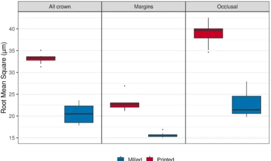
Results: The milled MZCs had a significantly higher trueness than the 3D-printed ones, overall [(90-10)/2 printed 37.8 µm vs milled 21.2 µm; ABS AVG printed 27.2 µm vs milled 15.1 µm; RMS printed 33.2 µm vs milled 20.5 µm;
p =0.000005], at the margins [(90-10)/2 printed 25.6 µm vs milled 12.4 µm; ABS AVG printed 17.8 µm vs milled 9.4 µm; RMS printed 22.8 µm vs milled 15.6 µm; p=0.000011] and at the occlusal level [(90-10)/2 printed 50.4 µm vs milled 21.9 µm; ABS AVG printed 29.6 µm vs milled 14.7 µm; RMS printed 38.9 µm vs milled 22.5 µm;
p =0.000005]. However, with regard to precision, both test and control groups scored highly, with no significant difference either in the quality of interproximal contact points (p =0.355) or marginal closure (p =0.355).
Conclusions: Milled MZCs had a statistically higher trueness than 3D-printed ones; all crowns, however, showed high precision, compatible with the clinical use.
Clinical significance: Although milled MZCs remain more accurate than 3D-printed ones, the LCM technique seems able to guarantee the production of clinically precise zirconia crowns.
Abbreviations: MZC, Monolithic zirconia crown; CAD, computer-assisted-design; STL, standard tessellation language; LCM, Lithography-based Ceramic Manufacturing; ABS AVG, absolute average; RMS, root mean square; CNC, computer numerical controlled; AM, additive manufacturing; SLA, stereolithography; DLP, digital light processing; FDM, fused deposition modeling; SLS, selective laser sintering; SLM, selective laser melting; CI, confidence interval; RICP, robust iterative closest point; SD, standard deviation; MD, mean difference; SRT, silicone replica technique; CSM, cross sectional method; TSM, triple scan method; MCT, micro computed tomography; OCT, optical coherence tomography.
* Corresponding author: Department of Pediatric, Preventive Dentistry and Orthodontics, , Sechenov First State Medical University, Bol’shaya Pirogovskaya Ulitsa, 19c1 Moscow, Russia.
E-mail addresses: h-lerner@web.de (H. Lerner), katalin.nagy@universityszeged.com (K. Nagy), nicola.pranno@uniroma1.it (N. Pranno), fernandozarone@mac.
com (F. Zarone), admakin1966@mail.ru (O. Admakin), francescoguidomangano@gmail.com (F. Mangano).
https://doi.org/10.1016/j.jdent.2021.103792
Received 30 July 2021; Received in revised form 14 August 2021; Accepted 18 August 2021
1. Introduction
Monolithic zirconia restorations manufactured by means of sub- tractive methods (milling) represents a reliable treatment option in modern prosthetic dentistry, as demonstrated in several clinical studies [1–7].
However, milling has some limitations, such as the considerable amount of raw material that is wasted (the material used for the supports and remnants of milled discs, which cannot be re-used). During milling, the burs are subject to abrasive wear, particularly when fully sintered ceramic material blocks are milled [8]. These blocks are dimensionally stable, but their milling can generate microcracks on the surface of the ceramic, which can compromise the longevity of the restoration [8,9]. A valid alternative is provided by using pre-sintered blocks or discs. The use of these more workable materials does not damage the burs; how- ever, the restorations are subject to dimensional changes after sintering, which may partially affect the accuracy [8]. Finally, with milling, the reproduction of surface geometry is dictated by the size of the milling burs, and the number of working axes of the computer numerical control (CNC) machine; therefore, in some applications (such as the milling of individual zirconia abutments), milling suffers from a limited ability to access smaller hollow areas and/or by-pass undercuts [8].
Modern additive manufacturing (AM) or 3D printing techniques promise to solve these problems [8,10,11]. AM is now used by pros- thodontists worldwide, for the fabrication of parts in resin (such as models [12,13], interim restorations [14], denture bases [15]) and in metal [16]. 3D printing allows the manufacture of extremely complex objects, hollow inside or with a gradient of material, without the limi- tations associated with other tools used for the classic molding, casting, and milling techniques [8,10,11,16]. Furthermore, 3D printing elimi- nates the waste of material, potentially reducing working time [8,11, 16].
Recently, technological evolution has paved the way for 3D printing of zirconia [17–19]. Several printing technologies have been employed to 3D print ceramics, including vat photopolymerization (stereo- lithography [SLA], digital light processing [DLP]) [20–23], direct inject printing [24,25], robocasting [26], fused deposition modeling (FDM) [27], selective laser sintering (SLS) and selective laser melting (SLM) technologies, direct energy deposition [28], sheet lamination, binder jetting [29].
To date, however, few studies have addressed the topic of 3D-printed zirconia prosthetic restorations [17,19,30–36]. As a result, some prob- lems remain unsolved, such as porosity control [8,30], mechanical reliability [31–33], sintering distortion, dimensional accuracy, and staircase surface effects [34–36].
In particular, there are very few studies in the literature about the accuracy of 3D-printed zirconia crowns [34–36]. One study has found acceptable trueness [35], but another has reported poor accuracy of the crowns, particularly regarding marginal tolerance, fit and prosthetic adaptation [36]. It is therefore still unclear whether zirconia crowns produced with 3D printing can be considered to be as accurate as those milled with conventional methods [17,19,34–36].
Hence, the aim of this in vitro study was to compare the trueness and precision of 3D-printed versus milled monolithic zirconia crowns (MZCs). In particular, the study aimed to compare the trueness (i.e., the correspondence between the printed/milled crowns and the reference CAD file, evaluated by industrial optical scanning) and the clinical precision (i.e., the marginal fit and quality of interproximal contacts, inspected on the model) of MZCs obtained through two different pro- duction processes, namely 3D printing (test group) versus milling (control group).
2. Materials and methods 2.1. Study design
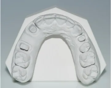
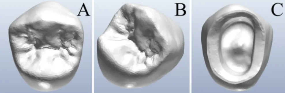
A gypsum reference model of a dentate maxilla with a prepared tooth (left first premolar) (Fig. 1) with 90◦shoulder preparation, was scanned with an industrial optical scanner (ATOS Q®, Gom GmbH, Braunsch- weig, Germany) (Fig. 2). The standard tessellation language (STL) file of this 3D acquisition (Fig. 3) was used to design a split-cast model (Fig. 4A, B) and a monolithic crown (Fig. 5A,B,C), in computer-assisted-design (CAD) software (DentalCad®, Exocad, Darmstadt, Germany). The crown was designed for production in zirconia. The CAD file of this crown (labeled as “reference crown”), saved in STL, was then printed with a Lithography-based Ceramic Manufacturing (LCM) printer (Cerafab S65®, Lithoz, Vienna, Austria). In total, 10 crowns (test group) were printed and sintered in full accordance with the manufacturer’s in- structions, and were ready for analysis. For the control group, the
“reference crown” STL file was milled with a 5-axis milling machine (DWX-52D®, DGShape, a Roland Company, Hamamatsu, Japan). In detail, 10 crowns (control group) were milled, sintered following the manufacturer’s instructions, and were ready for inspection. The 10 crowns of the test group and the 10 crowns of the control group (Fig. 6) were then scanned with the same aforementioned industrial optical scanner (ATOS Q®). Each crown was scanned when seated on the gypsum model, but also when free in space, in order that the entire anatomy (external and internal surfaces) was captured. The STL files (10 per group) derived from these optical scans were then compared with the reference CAD modeling file (“reference crown”), to evaluate true- ness, using reverse engineering software (Control X®, Geomagic, Mor- risville, NC, USA). Three sequences of superimpositions were performed.
First, the CAD file of the modeled crown used as a reference (“reference crown”) was superimposed on each scan of the 3D-printed and milled crowns, for the evaluation of the overall trueness of the crown surface.
Then, the reference CAD file was cut with dedicated tools to isolate, and select exclusively, first the surface of the margins (“reference marginal”) and then the external occlusal surface (“reference occlusal”). These sec- tions were subsequently used as references and superimposed on the scans of each individual test and control crown, for evaluation of mar- ginal and occlusal trueness respectively (Fig. 7). All superimpositions were performed inside the aforementioned software, where colorimetric maps were generated (Figs. 8–11). Then, a Mathlab user-code script (MathLab®, Mathworks) was developed to process the distance gaps exported from this reverse engineering software, in a .CSV format. Using
Fig. 1.A gypsum model of a dentate maxilla with a prepared tooth (left first premolar) served as reference for this study.
Mathlab®, the main outcome variables, i.e., the trueness of:
i the entire crown surface;
ii the marginal areas;
iii the occlusal surface;
of the MZCs were computed, and expressed as:
i Absolute average (ABS AVG);
ii Root mean square (RMS);
iii (90˚− 10˚)/2 (where 90˚is the 90th percentile and 10˚is the 10th percentile).
After having completed the trueness evaluation, the removable dies of the original CAD model on which the crown was designed, together with the model itself, were 3D-printed with a DLP printer (Solflex 350®, Voco, Cuxhaven, Germany). In all, 20 copies of the removable dies and a copy of the model were printed (Fig. 12)—being useful for verifying the clinical precision of each of the test and control MZCs, i.e., the quality of the interproximal contact points, as well as the marginal adaptation.
This evaluation was made by two different experienced calibrated prosthodontists using magnifying glasses (4.5x, Zeiss, Oberkochen, Germany). For each of the outcome variables (interproximal contacts, marginal closure) the two clinicians could express themselves in a vote that described the anatomical quality of the restorations. The grades that each clinician could assign were 5 (Excellent), 4 (Good), 3 (Sufficient), 2 Fig. 2. The industrial structured light scanner (ATOS Q®, Gom GmbH, Braunschweig, Germany) used in this study meets high metrological requirements, as it incorporates technology features such as the Triple Scan PrincipleTM, Blue Light EqualizerTM and precise calibration as a self-monitoring system with active tem- perature management. (For interpretation of the references to color in this figure legend, the reader is referred to the web version of this article.)
Fig. 3.The standard tessellation language (STL) file of the reference model acquired with the industrial optical scanner.
Fig. 4. A split-cast model was designed in a computer-assisted-design/ computer-assisted manufacturing (CAD) software (DentalCad®, Exocad, Darmstadt, Ger- many). A. Details of the removable die in position; B. The removable die free in the space.
(Insufficient) and 1 (Very poor). All collected trueness and precision data were collected in dedicated electronic spreadsheets (Excel®, Microsoft, Redmond, WA, USA) and were ready for statistical analysis.
2.2. Lithography-based ceramic manufacturing (LCM)
The Lithography-based Ceramic Manufacturing (LCM) process developed by Lithoz (Vienna, Austria) is based on the layer-by-layer curing of a ceramic suspension using visible (blue) light. The ceramic Fig. 5.A monolithic single crown was designed in a computer-assisted-design (CAD) software (DentalCad®, Exocad, Darmstadt, Germany). The crown was designed for production in zirconia. A. Occlusal view; B. Prospective view; C. View of the margins of the crown.
Fig. 6.Details of the 3D-printed and milled monolithic zirconia crowns (MZCs). In total, 20 samples were manufactured. Ten MZCs (test group, left of the picture) were 3D printed with a lithography-based ceramic manufacturing (LCM) printer (Cerafab S65®, Lithoz, Vienna, Austria), and other 10 MZCs (control group, right of the picture) were milled with a 5-axis milling machine (DWX-52D®, DGShape, a Roland Company, Hamamatsu, Japan). All crowns were sintered following the manufac- turer’s recommendation, and were ready for analysis. Different colors were used in order to facilitate the allocation of the samples in the correct group, eliminating any risk of confu- sion. (For interpretation of the references to color in this figure legend, the reader is referred to the web version of this article.)
Fig. 7. The STL files of the target models (20 in total, 10 per group) were compared with the reference CAD modeling file (“reference crown”), to evaluate trueness, using a reverse engineering software (Control X®, Geomagic, Morrisville, NC, USA). Three sequences of superimpositions were performed. First, the CAD file of the modeled crown used as a reference ("reference all crown") was superimposed on each scan of the 3D-printed and milled crowns, for the evaluation of the overall trueness of the crown surface. Then, the reference CAD file was cut with dedicated tools, in order to select exclusively the occlusal surface (“reference occlusal”), and the surface of the margins (“reference marginal”). These sections were subsequently used as references, and superimposed on the scans of each individual test and control crown, for evaluation of the occlusal and marginal trueness, respectively.
suspensions consist of photocurable resins, the respective ceramic powder (e.g., zirconia) and additives for optimal processability. The CAD file (STL-format) of the crown was split in layers by the computer and projected, layer by layer, onto a ceramic suspension, which was hardened/cured by photopolymerization, forming the so-called green body. The green body consists of the shape-giving polymer and the zirconia particles fixed within. In this study, all MZCs were fabricated with a CeraFab System S65® Medical 3D printing system (Lithoz, Vienna, Austria). CeraFab System S65® has a building envelope size of 102 ×64 mm. Parts up to a height of 320 mm can be printed with such machines, so that up to 50 crowns can be printed simultaneously in the same process. The lateral resolution of 40 µm and a variable layer height between 10 and 100 µm allow for the fabrication of precision restora- tions with minimal material consumption. The MZCs were produced from the raw material LithaCon 3Y 210® (Lithoz, Vienna, Austria), a ceramic suspension consisting of 3 mol% Yttria stabilized Zirconia (3- TZP) ceramic powder. After 3D printing, the green bodies must undergo
post-treatment: they are cleaned of excess material with a cleaning fluid (LithaSol 20®, Lithoz, Vienna, Austria) in specially developed cleaning stations (CeraCleaning Station Ultra®, Lithoz, Vienna, Austria) and then sintered to pure zirconium oxide in thermal post-processing. Sintering was carried out in a LHTCT 08/16® furnace (Nabertherm, Lilienthal, Germany) at temperatures of 1450 ◦C with a dwell time of 2 h under normal atmosphere (air) and without increased pressure. In this way, a density of 99.4% is reached.
2.3. Trueness evaluation
The 3D comparisons were performed by means of reverse engi- neering inspection software (Control X®, Geomagic, Morrisville, NC, USA). Three comparison groups were identified to analyze the accuracy of two different methods of fabrication. Simply put, three different se- quences of superimpositions were performed inside the aforementioned inspection software:
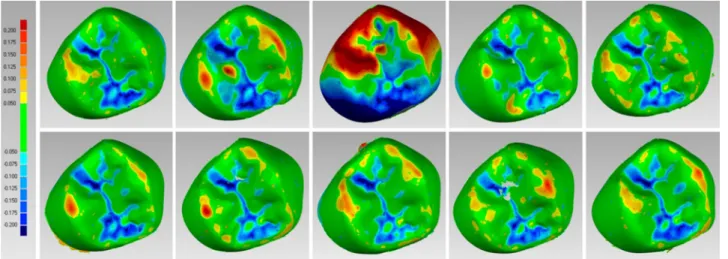
Fig. 8. Details of the colorimetric map generated in the reverse engineering software (Control X®, Geomagic, Morrisville, NC, USA) for the occlusal surface eval- uation of the ten 3D-printed crowns (test group). For the occlusal evaluation, the same setting was used for all models, with the color scale ranging from a maximum deviation of +200 μm to -200 μm, and the best result given by the deviations between +50 μm and -50 μm. The generated color map indicated an outward (red) or inward (blue) deviation between the overlaid structures, while a minimal displacement (<50 μm) was indicated by green color. (For interpretation of the references to color in this figure legend, the reader is referred to the web version of this article.)
Fig. 9. Details of the colorimetric map generated in the reverse engineering software (Control X®, Geomagic, Morrisville, NC, USA) for the occlusal surface eval- uation of the ten milled crowns (control group). For the occlusal evaluation, the same setting was used for all models, with the color scale ranging from a maximum deviation of +200 μm to -200 μm, and the best result given by the deviations between +50 μm and -50 μm. The generated color map indicated an outward (red) or inward (blue) deviation between the overlaid structures, while a minimal displacement (<50 μm) was indicated by green color. (For interpretation of the references to color in this figure legend, the reader is referred to the web version of this article.)
i The superimposition of each scanned test and control MZC onto the reference CAD file of the whole crown (“reference crown”), to eval- uate the overall trueness of the 3D-printed and milled crowns;
ii The superimposition of each scanned test and control MZC onto the reference CAD file of the occlusal surface of the crown (“reference
occlusal”), to evaluate the trueness of the occlusal surface of the 3D- printed and milled crowns;
iii The superimposition of each scanned test and control MZC onto the reference CAD file of the marginal surface of the crown (“reference marginal”), to evaluate the trueness of the marginal surface of the 3D- printed and milled crowns.
Fig. 10.Details of the colorimetric map generated in the reverse engineering software (Control X®, Geomagic, Morrisville, NC, USA) for the margins surface evaluation of the ten 3D-printed crowns (test group). For the margins surface evaluation, the same setting was used for all models, with the color scale ranging from a maximum deviation of +50 μm to -50 μm, and the best result given by the deviations between +10 μm and -10 μm. The generated color map indicated an outward (red) or inward (blue) deviation between the overlaid structures, while a minimal displacement (<10 μm) was indicated by green color. (For interpretation of the references to color in this figure legend, the reader is referred to the web version of this article.)
Fig. 11.Details of the colorimetric map generated in the reverse engineering software (Control X®, Geomagic, Morrisville, NC, USA) for the margins surface evaluation of the ten milled crowns (control group). For the margins surface evaluation, the same setting was used for all models, with the color scale ranging from a maximum deviation of +50 μm to -50 μm, and the best result given by the deviations between +10 μm and -10 μm. The generated color map indicated an outward (red) or inward (blue) deviation between the overlaid structures, while a minimal displacement (<10 μm) was indicated by green color. (For interpretation of the references to color in this figure legend, the reader is referred to the web version of this article.)
Each of the reference models (“reference crown”, “reference occlusal”
and “reference marginal”) was compared with the corresponding 20 target models: 10 fabricated by means of a 3D printing procedure and 10 fabricated by means of a milling procedure.
The procedure employed for each sequence of the superimpositions was as follows:
i The first step consisted in importing the .STL files in Geomagic Control X®. All files were firstly processed to fill holes and to elim- inate mesh problems. Subsequently the reference 3D model was set as “reference data” and the target model was set as “measured data”;
ii The second step consisted in the alignment process based on the best- fit robust-iterative-closest-point (RICP) alignment algorithm that was preceded by a rough alignment that was necessary to perform an accurate best-fit alignment. A minimum of 100 iterations were set per case and the distances between the reference CAD models and the scans of the MZCs were minimized using a point-to-plane method;
iii The third step consisted in setting the comparison parameters before starting the 3D comparison procedure. In order to calculate the de- viation value for every vertex in the measured data, the sampling ratio was set to 100%. Each measured vertex was defined by a measured position vector Pmi(xmi,ymi ,zmi)which is associated with a reference position vector Pri(xri,yri,zri)with i =1 to n, where n is the total number of compared points. By evaluating the vectors that go from Pmi to Pri the distance gap vector Di(xmi − xri,ymi − yri,zmi − zri)can be determined. The gap vectors were finally converted in scalar form Di=
̅̅̅̅̅̅̅̅̅̅̅̅̅̅̅̅̅̅̅̅̅̅̅̅̅̅̅̅̅̅̅̅̅̅̅̅̅̅̅̅̅̅̅̅̅̅̅̅̅̅̅̅̅̅̅̅̅̅̅̅̅̅̅̅̅̅̅̅̅̅̅̅̅̅̅
(xmi − xri)2+ (ymi − yri)2+ (zmi − zri)2
√
representing the devia- tion value at any given point. The gap distance was given in negative form when the measured point was on the negative side of the reference data. The software was therefore able to compute, for each point, the distances between the surfaces of the superimposed models, and to generate a colorimetric map useful to quantify and qualify the distances between specific points, overall and in all planes. The settings for the color scale ranged from a maximum de- viation of +50 μm to - 50 μm, to a minimum deviation of +10 μm and - 10 μm. With these settings, the map indicated outward (red) or inward (blue) deviations between the overlaid structures, while minimal displacements were indicated as green. The data retrieved from these superimpositions for each IOS were saved in specific electronic datasheets (Excel®, Microsoft, Redmond, WA, USA) ready
for analysis, whereas the visual screenshots derived from each single registration were saved in another format (PowerPoint®, Microsoft, Redmond, WA, USA);
iv The fourth step consisted in exporting the distance gap map in .CSV format. In fact, since the set of statistics obtained as output in Geo- magic Control X® is not satisfactory for our purposes, i.e., to compute absolute average (ABS AVG), root mean square (RMS) and (90˚− 10˚)/ 2 (where 90˚is the 90th percentile and 10˚is the 10th percentile), a Mathlab user-code script (MathLab®, Mathworks) was developed to post-process the distance gaps exported from this reverse engineering software, in a .CSV format;
v The distance gaps were imported in Matlab environment in the form of raw data that was firstly sorted from highest to lowest and then processed to compute the following statistical parameters, which were the trueness outcomes of this study: minimum distance, maximum distance, average (AVG), absolute average (ABS AVG), root mean square (RMS), standard deviation (SD), variance, positive average (ABS +), negative average (ABS− ), and (90˚− 10˚)/2 where 90˚ is the 90th percentile and 10˚is the 10th percentile.
2.4. Precision evaluation
The evaluation of the precision of the MZCs (test and control samples) was performed on the 3D-printed removable dies from the original CAD model on which the reference crown was designed. The master model and 20 identical copies of the removable die were printed with a DLP printer (Solflex 350®, Voco, Cuxhaven, Germany). The model and the removable dies were used by two calibrated experienced prosthodon- tists, for verifying the clinical precision of each test and control MZC, through the inspection of the following parameters:
i quality of the interproximal contact points. The quality of the interproximal contact points with the adjacent (mesial and distal) teeth was verified by inserting the removable die inside the 3D- printed master model and placing the corresponding MZC over it;
then, the operator checked the presence (or absence) of the inter- proximal contacts visually, using magnifying glasses (Zeiss 4.5x®, Zeiss, Oberkochen, Germany), and with a dental floss;
ii marginal adaptation. The quality of the marginal closure was investigated through visual inspection under magnification (Zeiss 4.5x®, Zeiss, Oberkochen, Germany) after having placed each MZC Fig. 12.The original computer-assisted-design (CAD) model on which the crown was designed and the removable die were 3D-printed with a digital light processing (DLP) printer (Solflex 350®, Voco, Cuxhaven, Germany). In total, 20 copies of the removable dies were printed. The model and the removable dies were printed to assess the clinical precision of each of the test and control monolithic zirconia crown (MZC), through the inspection of the marginal adaptation, and the quality of the occlusal and interproximal contact points.
on the corresponding, 3D-printed removable die. The evaluation was then completed by tactile analysis through a circumferential probing at the crown positioned on the removable die, with a periodontal probe. The purpose of this analysis was to assess the adaptation of the MZC onto the 3D-printed die and the presence of any defect, misfit, gap or undercut.
For each of the outcome variables (interproximal contacts, marginal closure) the two prosthodontists could score the anatomical quality of the restorations, from a clinical perspective. The scores that each clini- cian could assign were 5 (Excellent), 4 (Good), 3 (Sufficient), 2 (Insuf- ficient) and 1 (Very poor). For the evaluation of interproximal contact points, the presence of harmonious contact points resulted in good grades (5-4-3), whereas the absence (lack) of an interproximal contact, or the presence of an excessive contact that had to be removed or pol- ished, resulted in a bad grade (2-1). In the evaluation of the marginal adaptation, the prosthodontists carefully checked the presence of any defect, misfit, gap or undercut of the MZC on the removable die. The perfect 360◦adaptation of the MZC onto the removable die, without any visible or probable misfit or gap resulted in a good grade (5-4-3) whereas bad grades (2-1) were assigned in case of defects, gaps, misfits. All these data were collected in dedicated electronic spreadsheets (Excel®, Microsoft, Redmond, WA, USA) and used for analysis.
2.5. Statistical analysis
For the trueness evaluation, data processing, analysis and visuali- zation were performed using R (version 3.6.3) environment for statis- tical computing (R Foundation for Statistical Computing, Vienna, Austria), boot 1.3-24 and 1.3-1 packages. Descriptive statistics for quantitative variables were presented as medians (1st and 3rd quartiles) and means (±standard deviations). Medians and Gini’s mean difference (Gini’s MD, i.e. robust measure of variability, mean of all pairwise dif- ferences between observations) were used to measure the variation (htt ps://www.semanticscholar.org/paper/Gini%E2%80%99s-Mean-differe nce%3A-a-superior-measure-of-for-Yitzhaki/e4d00851cbbadf386e d051397cabff464a0d2585) with corresponding 95% adjusted bootstrap percentile confidence intervals. Permutation Wilcoxon–Mann–Whitney was used to compare manufacturing procedures, and permutation Wil- coxon signed-rank was used to compare paired distance measurements preformed in margins and occlusal levels, with mid p-value adjustment in both settings.
For the precision evaluation, all collected data were instead pro- cessed with statistical software (SPSS 25®, IBM, New York, NY, USA).
Average and confidence intervals (CI) 95% were assessed and comparative-error plots were obtained. Finally, significant correlations
were inspected with the non-parametric test of Mann-Whitney inde- pendent samples, as indicated for small sample sizes. Significance level was set at 0.05 level.
3. Results
Regarding the trueness evaluation, descriptive statistics for distance measurements and results of comparison were summarized in Table 1. A statistically significant difference in trueness was found between 3D- printed and milled crowns, in the three different evaluations (overall crown: p = 0.000005; margins: p = 0.000011; occlusal surface:
p = 0.000005). A significant difference in trueness was also found among the assessments made within the 3D-printed and milled groups, respectively. The results of estimation of (90-10)/2 distance medians and Gini’s MDs, conditional on the crowns’ levels and manufacturing process, were summarized in Table 2 and Figs. 13 and 14. Median dif- ferences between (90-10)/2 distances measured on margins and occlusal levels were 26.9 µm [95% CI: 17.4; 29] and 8.2 µm [95% CI: 3.8; 16] for printed and milled crowns, respectively. The results of estimation of ABS AVG distance medians and Gini’s MDs conditional on the crowns’ levels and manufacturing process were summarized in Table 3 and Figs. 15 and 16. Median differences between ABS AVG distances measured on mar- gins and occlusal levels were 13.1 µm [95% CI: 8.1; 13.8] and 4.2 µm [95% CI: 1.9; 9.8], for printed and milled crowns respectively. Finally, the results of estimation of RMS distance medians and Gini’s MDs, conditional on the crowns’ levels and manufacturing process, were summarized in Table 4 and Figs. 17 and 18. Median differences between RMS distances measured on margins and occlusal levels are 17.3 [95%
CI: 11.8; 18] micrometers and 6.4 [95% CI: 4.5; 10] micrometers for printed and milled crowns.
Finally, as regards clinical precision, the assessment made by the two prosthodontists was reported in Table 5 and Fig. 19. Both test (inter- proximal contact points: 4.40 ±0.94; marginal closure 4.40 ±0.88) and control (interproximal contact points 4.75 ± 0.44; marginal closure 4.74 ±0.44) groups scored highly, revealing excellent clinical precision
Table 1
Descriptive statistics for distance measurements (in µm) and results of comparison. P – p-values for comparisons between printed and milled crowns; P* – for com- parison between distance on margins and occlusal levels. Due to permutation character of these rank test p-values can take only discrete values [the similarity of p- values is not an error].
Measurement Manufacturing All crown Margins Occlusal P*
(90-10)/2 Printed 37.8 (1.4)
37.6 (37.0‒38.5) 25.6 (3.6)
24.8 (24.1‒25.2) 50.4 (4.7)
51.2 (49.8‒52.7) 0.000977
Milled 21.2 (4.7)
19.4 (18.6‒24.4) 12.4 (0.8)
12.3 (12.1‒12.8) 21.9 (5.8)
20.1 (17.7‒25.8) 0.001953
P 0.000005 0.000011 0.000005
Absolute average (ABS AVG) Printed 27.2 (1.3)
27.3 (26.6‒28.1) 17.8 (1.1)
18.0 (17.0‒18.2) 29.6 (2.5)
30.2 (28.6‒31.0) 0.000977
Milled 15.1 (2.2)
14.6 (13.4‒16.2) 9.4 (0.4)
9.5 (9.3‒9.5) 14.7 (3.8)
13.1 (11.8‒17.6) 0.001953
P 0.000005 0.000011 0.000005
Root Mean Square (RMS) Printed 33.2 (1.0)
33.3 (32.8‒33.6) 22.8 (1.6)
22.7 (22.0‒23.0) 38.9 (2.4)
39.6 (37.9‒40.0) 0.000977
Milled 20.5 (2.2)
20.5 (18.5‒22.3) 15.6 (0.6)
15.7 (15.3‒15.7) 22.5 (2.8)
21.4 (20.6‒24.5) 0.001953
P 0.000005 0.000011 0.000005
Table 2
Results of estimation of (90-10)/2 distances medians and Gini’s MDs conditional on the crown’s levels and manufacturing process.
Part Manufacturing Gini’s MD [95% CI] Median [95% CI]
All crown Printed 1.66 [1.22; 2.29] 37.58 [36.15; 38.40]
Milled 5.50 [3.96; 7.24] 19.42 [17.70; 23.75]
Margins Printed 2.97 [0.79; 6.62] 24.82 [23.83; 25.20]
Milled 0.93 [0.58; 1.41] 12.35 [11.40; 12.80]
Occlusal Printed 5.31 [3.11; 7.72] 51.20 [45.98; 52.81]
Milled 6.54 [4.37; 8.96] 20.15 [17.11; 27.35]
at the level of interproximal contact points and margins; therefore, no statistically significant difference was found in the precision among the different groups (test vs control groups), both for the interproximal
contact points (p =0.355) and the marginal closure (p =0.355). Finally, when testing if the investigator had an influence on the final evaluation, no differences among the scores given by the two prosthodontists were reported, either for the interproximal contact points (p =0.799) or for the marginal closure (p =0.799).
4. Discussion
The marginal fit is a determining factor for the survival and long- term success of prosthetic restorations, particularly with tooth- supported prostheses [37–41]. If a prosthetic crown does not close properly, the marginal discrepancy between the dental structure and the restoration can lead to dissolution of the cement [39,40], microleakage, risk of pulp inflammation [37] and formation of secondary caries [38, 39], as well as inflammation of the periodontal tissues [39,41]. To date, Fig. 13.Box-plots represent (90-10)/2 distances conditional on the crown’s levels and manufacturing process.
Fig. 14.Results of estimation of (90-10)/2 distances medians and Gini’s MDs conditional on the crown’s levels and manufacturing process.
Table 3
Results of estimation of absolute average (ABS AVG) distances medians and Gini’s MDs conditional on the crown’s levels and manufacturing process.
Part Manufacturing Gini’s MD [95% CI] Median [95% CI]
All crown Printed 1.56 [1.13; 2.21] 27.34 [26.01; 28.16]
Milled 2.57 [1.84; 3.35] 14.58 [13.28; 16.05]
Margins Printed 1.18 [0.72; 1.90] 18.00 [16.76; 18.17]
Milled 0.45 [0.27; 0.69] 9.48 [9.00; 9.50]
Occlusal Printed 2.85 [1.75; 4.22] 30.23 [27.29; 30.89]
Milled 4.36 [2.96; 5.66] 13.07 [11.45; 17.16]
although there is no univocal consensus in the scientific literature, marginal gaps between 50 and 120 µm are considered clinically acceptable; however, the ideal would be to obtain a closure with a gap of
less than 25 µm [39,42,43].
Monolithic zirconia is a widely used material today, for the manu- facture of single crowns, short- and long-span bridges, and full-arch restorations, both on natural teeth and on implants [1–7,44]. This so- lution has been particularly appreciated in the case of single-tooth restoration [2–5,44], and several studies have reported a marginal discrepancy for milled zirconia restorations between 15 and 120 µm [44-48]; in a recent systematic review based on 54 articles, a marginal gap for milled monolithic crowns between 7.6 µm and 206.3 µm was reported [42].
However, few studies exist on 3D printing of zirconia in dentistry [8, 17–19,30–32] and, in particular, on the analysis of marginal gaps with additively fabricated monolithic zirconia crowns [34–36].
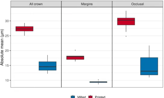
In a recent in vitro study, Wang et al. [35] compared the trueness of MZCs fabricated with SLA and conventional milling. The authors used a Fig. 15.Box-plots represent absolute average (ABS AVG) distances conditional on the crown’s levels and manufacturing process.
Fig. 16.Results of estimation of absolute average (ABS AVG) distances medians and Gini’s MDs conditional on the crown’s levels and manufacturing process.
Table 4
Results of estimation of root mean squared (RMS) distances medians and Gini’s MDs conditional on the crown’s levels and manufacturing process.
Part Manufacturing Gini’s MD [95% CI] Median [95% CI]
All crown Printed 1.18 [0.74; 1.90] 33.30 [32.35; 33.64]
Milled 2.65 [2.13; 3.12] 20.51 [18.10; 21.95]
Margins Printed 1.55 [0.68; 2.94] 22.72 [21.73; 23.01]
Milled 0.63 [0.34; 1.03] 15.65 [15.21; 15.70]
Occlusal Printed 2.75 [1.68; 4.02] 39.65 [36.34; 40.03]
Milled 3.19 [2.10; 4.32] 21.42 [20.28; 25.23]
Fig. 17.Box-plots represent root mean square (RMS) distances conditional on the crown’s levels and manufacturing process.
Fig. 18.Results of estimation of root mean square (RMS) distances medians and Gini’s MDs conditional on the crown’s levels and manufacturing process.
Table 5
Assessment of the clinical precision of the 3D printed (test) and milled (control) monolithic zirconia crowns (MZCs) performed by two different experienced pros- thodontists. The parameters assessed were the quality of the marginal closure and the quality of the interproximal contact points. For each of the outcome variables (interproximal contacts, marginal closure) the two prosthodontists could rate the anatomical quality of the restorations, from a clinical perspective. The rate each clinician could assign was 5 (excellent), 4 (good), 3 (sufficient), 2 (insufficient) and 1 (very poor).
Prosthodontist 1 Prosthodontist 2 Overall
3D printed MZCs
(test) Milled MZCs
(control) 3D printed MZCs
(test) Milled MZCs
(control) 3D printed MZCs
(test) Milled MZCs
(control) Interproximal contact
points 4.40 (±0.96) 4.70 (±0.48) 4.40 (±0.96) 4.80 (±0.42) 4.40 (±0.94) 4.75 (±0.44)
Marginal closure 4.40 (±0.96) 4.70 (±0.48) 4.40 (±0.96) 4.80 (±0.42) 4.40 (±0.88) 4.74 (±0.44)
reference typodont model, which was prepared for a monolithic crown and scanned with a desktop scanner [35]. A digital crown was designed within CAD software, and the modeling file was used to fabricate 10 MZCs by additive manufacturing (CERAMAKER 900®; 3DCeram Co, Limoges, France) and 10 MZCs by milling (DWX-50®, DGShape, a Roland Company, Hamamatsu, Japan) [35]. The crowns were then scanned with the same laboratory scanner, and the files thus obtained were superimposed on the reference CAD model, to evaluate trueness [35]. At the end of the study, the authors reported that the trueness of the samples made through AM was not lower than that of those made by milling [35].
These encouraging results were, at least in part, contradicted by a subsequent in vitro study, where Revilla Leon et al. [36] measured and compared the marginal and internal discrepancies of AM and milled MZCs, using the silicone replica technique (SRT). In this study, an individualized implant abutment was scanned with a laboratory scanner and the authors designed an anatomical crown in CAD, which was milled and printed in monolithic zirconia; finally, a third group of crowns were 3D-printed, but splinted in two parts, to simulate the structures of enamel and dentin [36]. Ten samples were produced for each group, and the additive manufacturing samples were fabricated with the aforementioned SLA machine (CERAMAKER 900®; 3DCeram Co, Limoges, France), which processed a dedicated material (3DMix ZrO2® paste; 3DCeram Co) [36]. A conventional 5-axis machine was used for milling. The authors then employed the silicone replication technique to measure marginal and internal discrepancies, using a x100 magnification microscope. At the end of the study, the authors found significant differences in marginal and internal discrepancies between the groups [36]. The milled MZCs, in fact, had the least degree of marginal and internal discrepancies, compared to the 3D-printed crowns (monolithic and splinted into 2 parts); on the other hand, within the group of 3D-printed parts, the splinted crowns revealed lower values of marginal discrepancy [36]. The authors concluded that the milled and printed crowns that were splinted in two parts showed clinically
acceptable marginal and internal discrepancies, while the group of 3D-printed MZCs showed marginal and internal discrepancies that were unacceptable, and incompatible with clinical use [36].
The difference between the results reported by these two studies—- which used, among other things, the same 3D printer for manufacturing the prosthetic crowns—could reside in the different methodology and evaluation criteria applied to evaluate the accuracy of the restorations.
In a recent study, Son et al. [43], have compared five different methods (SRT, cross-sectional method [CSM], triple scan method [TSM], micro-computed tomography [MCT], and optical coherence tomogra- phy [OCT]) to evaluate the marginal and internal fit of a specially designed coping on an abutment. The five methods showed significant differences in the four regions that were assessed (p <0.001) [43], and the authors concluded that the marginal and internal fit showed sig- nificant differences, depending on the method used for inspection [43].
Hence, the different methods employed to evaluate the marginal gap by Wang [35] and Revilla-Leon [36] may justify these different results.
Wang et al. [35] in fact, scanned the crowns obtained by 3D printing and milling with a dental desktop scanner, and they superimposed the .STL files obtained on the reference CAD file of the prosthetic crown. At the end of their evaluation, the mean trueness for the marginal surface only, calculated with the RMS method, amounted to 34 (±5) µm in the 3D-printed crowns group, versus 35 (±7) in the milled crowns group [35]. Revilla-Leon et al., instead, used an SRT, and found median (± interquartile) marginal gaps of 37.5 µm (±50) and 146.0 µm (±103.2) for CNC and AM MZCs respectively [36].
In our present in vitro study, we have compared the trueness and precision of MZCs produced by AM versus milling. The 3D-printed crowns (test group) were manufactured using a novel method, the LCM; the printer used was a CeraFab System S65® Medical 3D printing system (Lithoz, Vienna, Austria). Our milled crowns (control group) were manufactured with a modern 5-axis milling unit (DWX-52D®, DGShape, a Roland Company, Hamamatsu, Japan). According to ISO 5725,
“trueness” refers to the closeness of agreement between the arithmetic Fig. 19.Box-plot comparing averages at 95% confidence intervals (CI) for the precision of the MZCs at the level of interproximal contact points and margins. For each of the outcome variables (interproximal contacts, marginal closure) the two investigators could rate the anatomical quality of the restorations, from a clinical perspective. The rate each clinician could assign was 5 (excellent), 4 (good), 3 (sufficient), 2 (insufficient) and 1 (very poor). The values are distinguished between tests and controls, and between the two investigators.
AVG, RMS, and (90-10)/2 percentile method, were obtained for both test and control groups in a computing platform (MathLab®, Mathworks), and used for statistical analysis. The ABS AVG is one of the most commonly used outcomes of in vitro studies evaluating trueness, and it is considered better than the signed mean, since it avoids those positive and negative deviations between reference and test objects that could lead to results cancelling each other. The RMS error (equal to standard deviation) is another common method used to evaluate trueness; finally, the (90-10)/2 percentile is another method, whereby the highest and lowest 10 percent of the surface are not taken into account, because of margin effects and the different scan sizes of models.
At the end of our study, the conventional milling technique proved to be more accurate than the new 3D printing technology, with statistically significant differences in trueness between the milled and 3D-printed samples in all three inspected areas (overall crown, marginal area, occlusal surface), with all three methods applied (90-10/2, ABS AVG, RMS). These results seem to confirm the evidence presented in the study of Revilla-Leon et al. [36].
However, in our study, the differences between test (3D-printed) and control (milled) samples appeared particularly marked at the level of the occlusal surface, where the 3D-printed crowns showed the highest de- viations. Although statistically significant, the difference in accuracy between 3D-printed and milled MZCs was less marked in the marginal area. This resulted in a significant difference in accuracy between the different areas, even within the same groups (tests and controls).
In fact, in 3D printing the accurate reproduction of the cusps can suffer from the presence of the printing supports, which must be posi- tioned also at the occlusal level, unlike what happens in milled crowns.
When the dental technician removes these supports, there is a risk to over or under polish; this can have an effect on the trueness of this functional surface. However, in the present study the largest deviations from the original CAD file were found in the occlusal grooves and pits of the 3D printed crowns. These deviations today represent a limitation of the LCM printing technique, which struggles to accurately reproduce deep and narrow grooves, particularly where their presence determines a marked asymmetry or discrepancy in the thickness of the crown walls.
In the CAD design of crowns to be printed through LCM, it is always preferable to avoid modeling with deep and narrow grooves, because this anatomy can cause problems in the printing process. Unfortunately, in our present study, we did not perform an evaluation of the clinical precision of the occlusion of the MZCs, since we did not have an antagonist model. This is a limit of the study.
Nevertheless, the precision of the 3D-printed and milled crowns, verified on the model through the analysis of parameters such as the marginal fit, and the quality of the interproximal contacts, was similar and fully in the range of clinical acceptability. This result seems to point in the direction shown by Wang et al. [35]—who reported a RMS of 53 µm for the external surface, 38 µm for the intaglio surface, and 27 µm for the intaglio occlusal surface of 3D-printed MZCs, versus 52, 43 and 41 µm for milled MZCs, respectively—and contradict the results of
our research, the trueness of the MZCs was assessed through an indus- trial scanner, on limited samples of test and control crowns. The evalu- ation of clinical precision was also carried out in vitro, by only two operators, on a split-cast model. In order to confirm the data emerging from this research, further in vitro studies on more numerous samples of MZCs are needed, also conducted using different evaluation methods (CSM, SRT, TSM, MCT and OCT); in addition, clinical proof is needed, i.
e., the evaluation of the fit of the restorations in vivo. Randomized and controlled clinical trials should therefore be conducted, preferably in a University setting, in order to definitively validate the clinical use of 3D-printed zirconia restorations.
5. Conclusions
Within its limits (in vitro design, limited number of samples evalu- ated, only one evaluation method), the present study compared the trueness and precision of 3D-printed versus milled monolithic zirconia crowns (MZCs), and found that milled MZCs have a statistically signif- icant higher trueness than 3D-printed MZCs. In this study, both 3D- printed and milled crowns showed high precision, compatible with the clinical use. However, more research is certainly needed to evaluate the clinical precision and mechanical resistance of 3D printed zirconia res- torations, and to validate their clinical use.
CRediT authorship contribution statement
Henriette Lerner: Funding acquisition, Resources, Validation, Investigation, Methodology, Writing – review & editing. Katalin Nagy:
Project administration, Validation, Methodology, Writing – review &
editing. Nicola Pranno: Data curation, Formal analysis. Fernando Zarone: Supervision, Writing – review & editing. Oleg Admakin: Su- pervision, Writing – review & editing. Francesco Mangano: Concep- tualization, Investigation, Methodology, Software, Writing – original draft, Visualization, Investigation.
Declaration of Competing Interest
The authors declare that they have no known competing financial interests or personal relationships that could have appeared to influence the work reported in this paper.
Acknowledgments
The authors are grateful to Master Dental Technician Uli Hauschild, for the preparation of the model used for this study; to Dr. Davide Far- ronato and Dr. Bidzina Margiani, for help with the statistical analysis; to Dr. Daniel Bomze, Dr. Michael Djebali and Dr. Mouad El Ouafiq, for help with preparing the 3D-printed and milled samples; and finally, to Dr.
Gabriele Graziosi, for help with the industrial optical scanner.
References
[1] L.C. Mazza, C.A.A. Lemos, A.A. Pesqueira, E.P. Pellizzer, Survival and
complications of monolithic ceramic for tooth-supported fixed dental prostheses: a systematic review and meta-analysis, J. Prosthet. Dent. (2021 Mar 18), https://doi.
org/10.1016/j.prosdent.2021.01.020. S0022-3913(21)00065-2online ahead of print.
[2] E.F. Cagidiaco, N. Discepoli, C. Goracci, F. Carboncini, P. Vigolo, M. Ferrari, Randomized clinical trial on single zirconia crowns with feather-edge vs chamfer finish lines: four-year results, Int. J. Periodontics Restor. Dent. 39 (2019) 817–826, https://doi.org/10.11607/prd.4270.
[3] S. Mühlemann, T. Lakha, R.E. Jung, C.H.F. H¨ammerle, G.I. Benic, Prosthetic outcomes and clinical performance of CAD-CAM monolithic zirconia versus porcelain-fused-to-metal implant crowns in the molar region: 1-year results of a RCT, Clin. Oral. Implants Res. 31 (2020) 856–864, https://doi.org/10.1111/
clr.13631.
[4] F. Mangano, G. Veronesi, Digital versus analog procedures for the prosthetic restoration of single implants: a randomized controlled trial with 1 year of follow- up, Biomed. Res. Int. 2018 (2018), 5325032, https://doi.org/10.1155/2018/
5325032.
[5] R.D. Kraus, A. Epprecht, C.H.F. H¨ammerle, I. Sailer, D.S. Thoma, Cemented vs screw-retained zirconia-based single implant reconstructions: a 3-year prospective randomized controlled clinical trial, Clin. Implant Dent. Relat. Res. 21 (2019) 578–585, https://doi.org/10.1111/cid.12735.
[6] M. Tabesh, F. Nejatidanesh, G. Savabi, A. Davoudi, O. Savabi, H. Mirmohammadi, Marginal adaptation of zirconia complete-coverage fixed dental restorations made from digital scans or conventional impressions: a systematic review and meta- analysis, J. Prosthet. Dent. 125 (2021) 603–610, https://doi.org/10.1016/j.
prosdent.2020.01.035.
[7] A.A. Abdulmajeed, K.G. Lim, T.O. N¨arhi, L.F. Cooper, Complete-arch implant- supported monolithic zirconia fixed dental prostheses: a systematic review, J. Prosthet. Dent. 115 (2016) 672–677, https://doi.org/10.1016/j.
prosdent.2015.08.025.
[8] M.M. Methani, M. Revilla-Le´on, A. Zandinejad, The potential of additive manufacturing technologies and their processing parameters for the fabrication of all-ceramic crowns: a review, J. Esthet. Restor. Dent. 32 (2020) 182–192, https://
doi.org/10.1111/jerd.12535.
[9] H. Huang, Machining characteristics and surface integrity of yttria stabilized tetragonal zirconia in high speed deep grinding, J. Mater. Sci. Eng. A 345 (2003) 155–163.
[10] N. Alharbi, D. Wismeijer, R.B. Osman, Additive manufacturing techniques in prosthodontics: where do we currently stand? A critical review, Int. J. Prosthodont.
30 (2017) 474–484, https://doi.org/10.11607/ijp.5079.
[11] A. Barazanchi, K.C. Li, B. Al-Amleh, K. Lyons, J.N. Waddell, Additive technology:
update on current materials and applications in dentistry, J. Prosthodont. 26 (2017) 156–163, https://doi.org/10.1111/jopr.12510.
[12] O. Rungrojwittayakul, J.Y. Kan, K. Shiozaki, R.S. Swamidass, B.J. Goodacre, C.
J. Goodacre, J.L. Lozada, Accuracy of 3D printed models created by two technologies of printers with different designs of model base, J. Prosthodont. 29 (2020) 124–128, https://doi.org/10.1111/jopr.13107.
[13] F.G. Mangano, O. Admakin, M. Bonacina, F. Biaggini, D. Farronato, H. Lerner, Accuracy of 6 desktop 3D printers in dentistry: a comparative in vitro study, Eur. J.
Prosthodont. Restor. Dent. 28 (2020) 75–85, https://doi.org/10.1922/EJPRD_
2050Mangano11.
[14] N. Martín-Ortega, A. Sallorenzo, J. Casajús, A. Cervera, M. Revilla-Le´on, M.
J. Gomez-Polo, Fracture resistance of additive manufactured and milled implant- ´ supported interim crowns, J. Prosthet. Dent. (2021 Jan 8), https://doi.org/
10.1016/j.prosdent.2020.11.017. S0022-3913(20)30735-6Online ahead of print.
[15] E. Anadioti, L. Musharbash, M.B. Blatz, G. Papavasiliou, P. Kamposiora, 3D printed complete removable dental prostheses: a narrative review, BMC Oral. Health 20 (2020) 343, https://doi.org/10.1186/s12903-020-01328-8.
[16] M. Revilla-Le´on, M.J Meyer, M. Ozcan, Metal additive manufacturing technologies: ¨ literature review of current status and prosthodontic applications, Int. J. Comput.
Dent. 22 (2019) 55–67.
[17] M. Revilla-Le´on, M.J. Meyer, A. Zandinejad, M. Ozcan, Additive manufacturing ¨ technologies for processing zirconia in dental applications, Int. J. Comput. Dent. 23 (2020) 27–37.
[18] R. Galante, C.G. Figueiredo-Pina, A.P. Serro, Additive manufacturing of ceramics for dental applications: a review, Dent. Mater. 35 (2019) 825–846, https://doi.org/
10.1016/j.dental.2019.02.026.
[19] J. Schweiger, D. Edelhoff, J.F. Güth, 3D printing in digital prosthetic dentistry: an overview of recent developments in additive manufacturing, J. Clin. Med. 10 (2021) 2010, https://doi.org/10.3390/jcm10092010.
[20] M.L. Griffith, J.W. Halloran, Stereolithography of ceramics, J. Am. Ceram. Soc. 82 (1995) 1653–1658.
[21] C. Hinczewski, S. Corbel, T. Chartier, Ceramic suspensions suitable for stereolithography, J. Eur. Ceram. Soc. 18 (1998) 583–590.
[22] F. Doreau, C. Chaput, T. Chartier, Stereolithography for manufacturing ceramic parts, Adv. Eng. Mater. 2 (2000) 493–496.
[23] M. Dehurtevent, L. Robberecht, J.C. Hornez, A. Thuault, E. Deveaux, P. B´ehin, Stereolithography: a new method for processing dental ceramics by additive computer-aided manufacturing, Dent. Mater. 33 (2017) 477–485, https://doi.org/
10.1016/j.dental.2017.01.018.
[24] J. Ebert, E. Ozkol, A. Zeichner, K. Uibel, O. Weiss, U. Koops, R. Telle, H. Fischer, Direct inkjet printing of dental prostheses made of zirconia, J. Dent. Res. 88 (2009) 673–676, https://doi.org/10.1177/0022034509339988.
[25] E. Ozkol, W. Zhang, J. Ebert, R. Telle, Potentials of the ¨ “direct inkjet printing” method for manufacturing 3Y-TZP based dental restorations, J. Eur. Ceram. Soc. 32 (2012) 2193–2201.
[26] N.R. Silva, L. Witek, P.G. Coelho, V.P. Thompson, E.D. Rekow, J. Smay, Additive CAD/CAM process for dental prostheses, J. Prosthodont. 20 (2011) 93–96, https://
doi.org/10.1111/j.1532-849X.2010.00623.x.
[27] M.W.M. Cunico, Investigation of ceramic dental prostheses based on ZrSiO(4)-glass composites fabricated by indirect additive manufacturing, Int. J. Bioprint. 7 (2020) 315, https://doi.org/10.18063/ijb.v7i1.315.
[28] V.K. Balla, S. Bose, A. Bandyopadhyay, Processing of bulk alumina ceramics using laser engineered net shaping, Int. J. Appl. Ceram. Technol. 5 (2008) 234–242.
[29] I. Gibson, D.W. Rosen, B. Stucker, Sheet lamination processes, in: I Gibson, DW Rosen, B Stucker (Eds.), Additive Manufacturing Technologies: Rapid Prototyping to Direct Digital Manufacturing, Springer, Boston, MA, 2010, pp. 207–231.
[30] C. Marsico, M. Øilo, J. Kutsch, M. Kauf, D. Arola, Vat polymerization-printed partially stabilized zirconia: mechanical properties, reliability and structural defects, Addit. Manuf. 36 (2020), 101450, https://doi.org/10.1016/j.
addma.2020.101450.
[31] M. Revilla-Le´on, N. Al-Haj Husain, L. Ceballos, M. Ozcan, Flexural strength and ¨ Weibull characteristics of stereolithography additive manufactured versus milled zirconia, J. Prosthet. Dent. 125 (2021) 685–690, https://doi.org/10.1016/j.
prosdent.2020.01.019.
[32] A. Zandinejad, M.M. Methani, E.D. Schneiderman, M. Revilla-Le´on, D. Morton, Fracture resistance of additively manufactured zirconia crowns when cemented to implant supported zirconia abutments: an in vitro study, J. Prosthodont. 28 (2019) 893–897, https://doi.org/10.1111/jopr.13103.
[33] R. Li, H. Chen, Y. Wang, Y. Sun, Performance of stereolithography and milling in fabricating monolithic zirconia crowns with different finish line designs, J. Mech.
Behav. Biomed. Mater. 115 (2021), 104255, https://doi.org/10.1016/j.
jmbbm.2020.104255.
[34] R. Li, Y. Wang, M. Hu, Y.Xv Y.Wang, Y. Liu, Y. Sun, Strength and adaptation of stereolithography-fabricated zirconia dental crowns: an in vitro study, Int. J.
Prosthodont. 32 (2019) 439–443, https://doi.org/10.11607/ijp.6262.
[35] W. Wang, H. Yu, Y. Liu, X. Jiang, B. Gao, Trueness analysis of zirconia crowns fabricated with 3-dimensional printing, J. Prosthet. Dent. 121 (2019) 285–291, https://doi.org/10.1016/j.prosdent.2018.04.012.
[36] M. Revilla-Le´on, M.M. Methani, D. Morton, A. Zandinejad, Internal and marginal discrepancies associated with stereolithography (SLA) additively manufactured zirconia crowns, J. Prosthet. Dent. 124 (2020) 730–737, https://doi.org/10.1016/
j.prosdent.2019.09.018.
[37] T.D. Larson, The clinical significance of marginal fit, Northwest Dent. 91 (2012) 22–29.
[38] R. Holmes, S.C. Bayne, G.A. Holland, W.D. Sulik, Considerations in measurement of marginal fit, J. Prosthet. Dent. 62 (1989) 405–408, https://doi.org/10.1016/0022- 3913(89)90170-4.
[39] M. Hasanzade, M. Aminikhah, K.I. Afrashtehfar, M. Alikhasi, Marginal and internal adaptation of single crowns and fixed dental prostheses by using digital and conventional workflows: a systematic review and meta-analysis, J. Prosthet. Dent.
(2020 Sep 12), https://doi.org/10.1016/j.prosdent.2020.07.007. S0022-3913(20) 30412-1Online ahead of print.
[40] M.S. Jacobs, A.S. Windeler, An investigation of dental luting cement solubility as a function of the marginal gap, J. Prosthet. Dent. 65 (1991) 436–442, https://doi.
org/10.1016/0022-3913(91)90239-s.
[41] D.A. Felton, B.E. Kanoy, S.C. Bayne, G.P. Wirthman, Effect of in vivo crown margin discrepancies on periodontal health, J. Prosthet. Dent. 65 (1991) 357–364, https://
doi.org/10.1016/0022-3913(91)90225-l.
[42] M. Contrepois, A. Soenen, M. Bartala, O. Laviole, Marginal adaptation of ceramic crowns: a systematic review, J. Prosthet. Dent. 110 (2013) 447–454, https://doi.
org/10.1016/j.prosdent.2013.08.003, e10.
[43] K. Son, S. Lee, S.H. Kang, J. Park, K.B. Lee, M. Jeon, B.J. Yun, A comparison study of marginal and internal fit assessment methods for fixed dental prostheses, J. Clin.
Med. 8 (2019) 785, https://doi.org/10.3390/jcm8060785.
[44] H. Laumbacher, T. Strasser, H. Knüttel, M. Rosentritt, Long-term clinical performance and complications of zirconia-based tooth- and implant-supported fixed prosthodontic restorations: A summary of systematic reviews, J. Dent. 111 (2021 Jun 11), 103723, https://doi.org/10.1016/j.jdent.2021.103723. Online ahead of print.
[45] Y. Freire, E. Gonzalo, C. Lopez-Suarez, J. Pelaez, M.J. Suarez, Evaluation of the marginal fit of monolithic crowns fabricated by direct and indirect digitization, J. Prosthodont. Res. (2020 Oct 9), https://doi.org/10.2186/jpr.JPR_D_20_00003.
Online ahead of print.
[46] M. Del Pinal, C. Lopez-Suarez, J.F. Bartolome, C.A. Volpato, M.J. Suarez, Effect of ˜ cementation and aging on the marginal fit of veneered and monolithic zirconia and metal-ceramic CAD-CAM crowns, J. Prosthet. Dent. 125 (2021), https://doi.org/
10.1016/j.prosdent.2020.06.036, 323.e1–323.e7.
[47] I.M. Carrilho Baltazar, J.F. Vaz, Pimentel Coelho Lino Carracho, Marginal fit of zirconia copings fabricated after conventional impression making and digital scanning: An in vitro study, J. Prosthet. Dent. 124 (2020), https://doi.org/
10.1016/j.prosdent.2020.02.011, 223.e1–223.e6.
[48] W.M. Ahmed, M.N. Abdallah, A.P. McCullagh, C.C.L. Wyatt, T. Troczynski, R.
M. Carvalho, Marginal discrepancies of monolithic zirconia crowns: the influence