The Measurement of Radioactivity for Tracer Applications
B Y
ALOIS LANGER
Westinghouse Research Laboratories, East Pittsburgh, Pennsylvania
CONTENTS
Page
1. General Use of Radioactive Measurements 440
1.1. Study of Radioactivity 440 1.2. Applied Radioactivity 440 2. Photographic Method of Detection 441
2.1. Blackening of the Photographic Emulsion 441 2.2. Radioactivity Distribution Determination 442
2.3. Radiation Dosimetry 443 3. Electric Methods of Detection 443
3.1. Collection of Charged Particles 443 3.2. Ionization Measurements 444
3.2.1. Principle of Ionization 444 3.2.2. Ionization Chamber Constructions 445
3.2.3. Detecting Devices 449 Galvanometers 449 Electrometers 449 Electrometer tube amplifiers 451
3.2.4. Methods of Measurement 452 3.3. Measurements by Counting 456
3.3.1. Principle of Counters 456 3.3.2. Construction of Counters 459 3.3.3. Auxiliary Equipment 464 3.3.4. Tests of Counting Equipment 467
3.3.5. Preparation of Samples 473 Solid samples 474 Liquid samples 480 Gaseous samples 481 3.3.6. Corrections Introduced by the Sample 482
3.3.7. Statistics of Counting and Sample Strength 489
4. Special Analytical Procedures 490 4.1. General Assumptions and Methods 490
4.2. Radiometric Titration 493 4.3. Radioactive Isotope Dilution Procedures 496
5. Protection Measures 497
References 498 439
1. G E N E R A L U S E O F R A D I O A C T I V E M E A S U R E M E N T S
1.1. Study of Radioactivity
T h e determination of radioactivity is of value in several fields of research. Predominant among these is t h e s t u d y of t h e phenomena con- cerned with t h e atomic nucleus. A considerable refinement in methods can be noted from t h e time of t h e discovery of radioactivity and the isolation of radium t o t h e discovery of fission and the creation of trans- uranic elements. B y radioactive measurements one seeks t o establish t h e scheme and half period of t h e decay of unstable nuclei. This involves finding on a q u a n t i t a t i v e basis t h e t y p e of t h e emitted radiation and its energy distribution.
1.2. Applied Radioactivity
The use of radioactive measurements as an analytical procedure is steadily gaining in importance, since radioactive elements a n d com- pounds have numerous applications in m a n y branches of scientific and practical investigation. These applications were extended recently by the construction of uranium piles, which can supply perhaps a million times more of certain radioactive isotopes t h a n a cyclotron.
T h e usefulness of these isotopes is due mainly t o t h e sensitivity of radioactive measurements a n d t h e basic properties of t h e radioactive atoms. T h e radioactive elements can be detected a n d quantitatively determined in exceedingly small a m o u n t s . Under proper conditions of half-life, t y p e , and energy of t h e emitted radiation, t h e y are determinable by measurement of activity in concentrations m a n y times smaller t h a n by any other known chemical or physical method. F u r t h e r m o r e , by n a t u r e of its radioactivity, a given atom is labeled so t h a t one can deter- mine its position at t h e occurrence of t h e disintegration process among a great excess of nonactive species. T h e characteristics of the emitted radiation are also an identification of t h e radioactive isotope.
While t h e sensitivity a n d ease of detection makes t h e application of radioactive isotopes very convenient, for example in solubility and vapor pressure measurements, t h e labeled p r o p e r t y is particularly useful in tracing t h e element t h r o u g h t h e process under investigation (49).
Experiments like self diffusion a n d exchange reactions (45) can be per- formed, which, without labeled tracers, were impossible. Because radio- active elements are detected b y their emitted radiation, t h e determina- tion can often be m a d e at a considerable distance from t h e sample. I n some cases a continuous s t u d y of processes can be made, without any alteration or disturbance of the system ( 1 8 ) , as in t h e study of metabolism on living organisms.
M E A S U R E M E N T O F R A D I O A C T I V I T Y F O R T R A C E R A P P L I C A T I O N S 441
Since atoms having t h e p r o p e r t y of spontaneous disintegration differ from the stable nuclei by only a slight shift ui atomic weight, this difference does not ordinarily play a measurable role in t h e processes which are being studied, except for cases of isotope separation. This is particularly t r u e of t h e heavier elements. Because m i n u t e a m o u n t s of t h e radioactive elements can be detected in an excess of t h e stable nuclei, t h e decay products or t h e e m i t t e d radiation do not alter t h e normal process of t h e investigated phenomena. These investigations, are.
therefore, often called radioactive tracer or radioactive indicator methods, Radioactive tracer m e t h o d s can sometimes be replaced or supplemented using t h e enriched heavy or light stable isotopes analyzed with a mass spectrometer.
Although t h e radioactive processes give rise t o m a n y kinds of radia
tion, their detection in principle, depends on t h e fact t h a t t h e emitted radiation interacts with t h e surrounding m a t t e r , losing p a r t or t h e whole of its energy a n d producing electrical, thermal, optical, chemical or other changes.
I n nuclear physics one has t o deal with m a n y types of particles, such as neutrons, protons, deuterons, recoil a t o m s from fission, mesons, and others. I n tracer work one encounters mainly alpha, beta, and g a m m a radiation, with a wide spread of energy content. I n tracer application one rarely uses cloud chambers, differential calorimeters, or beta-ray spectrographs for measurements, b u t relies mainly on t h e action of radiation upon photographic emulsion a n d on t h e ionization effect, whereby gases and other normally insulating media are m a d e conductive.
2. P H O T O G R A P H I C M E T H O D O F D E T E C T I O N
2.1. Blackening of the Photographic Emulsion by Radiation T h e effect on the photographic emulsion b y electromagnetic a n d corpuscular rays has, since t h e discovery of radioactivity, never ceased t o be an i m p o r t a n t detecting device for radiation. T h e blackening of a film is a complicated function of several p a r a m e t e r s . T h e most impor
t a n t of these are t h e plate itself, t h e quality a n d intensity of t h e radia
tion, t h e time of exposure and t h e process of developing. T h e blacken
ing (B) or density of a photographic emulsion is defined as Β = log y * where Iq is t h e intensity of a parallel monochromatic b e a m of visible light falling on t h e film, a n d / t h e intensity t r a n s m i t t e d b y t h e film.
As a good approximation t h e blackening depends only on t h e a m o u n t (M) of t h e radiation received regardless of t h e time interval (t) during which t h e film is exposed. This reciprocity law, holding for energetic
radiation, b u t not for visible light, can be expressed a s : Β = }{M) = f(g-t) where (g) is t h e intensity of t h e emitted radiation. T h e blackening of t h e emulsion is proportional t o t h e a m o u n t of radiation in a limited range only. This is due t o t h e fact t h a t silver particles, once activated, are lost for activation b y a n y further radiation impinging on t h e same point. Therefore, t h e blackening shows a saturation effect, following an exponential curve. If (Ao) is t h e q u a n t i t y of available silver nuclei in t h e unexposed film t h e n : Β = KA0(l — e~hM). For a q u a n t i t a tive determination of (M) constants (K) a n d (h) m u s t be empirically evaluated.
2.2. Radioactivity Distribution Determinations
T h e present d a y use of t h e photographic emulsion is primarily for comparison of t h e two dimensional distribution of radioactive material in plane solid samples (18). T h e procedure is based on t h e fact t h a t very small a m o u n t s of radiation can be recorded if long enough exposure times are used, a n d t h a t an easily visible representation of the intensity distribution is obtained in a p e r m a n e n t picture. This procedure is more rapid t h a n m a p p i n g t h e specimen point b y point using small ionization chambers or counters.
Usually flat t h i n sections are prepared b y t h e well known methods for microscopic examination, and t h e specimen is p u t on t h e photographic plate either in direct contact, or with a thin sheet of cellophane, paper, or mica interposed t o eliminate blackening b y effects other t h a n radiation.
T h e exposure time, which varies from minutes t o weeks, is determined conveniently from empirical tables. For a given radiation a n d film material t h e exposure time is adjusted t o t h e overall radioactivity of the specimen a n d t h e half life of t h e isotope. I n exposures lasting longer t h a n t w o half lives no appreciable additional blackening is obtained.
Fine grain x-ray films, metallographic plates, or special alpha-ray plates are satisfactory for this purpose.
These enlarged autoradiographs are compared with light microscope pictures of t h e same magnification, a n d valuable information concerning t h e distribution of t h e radioactive a t o m s in the material can be obtained.
I n case penetrating beta rays are emitted b y t h e sample a diffuse image will result for several reasons. T h e blackened grains are spread along t h e whole track of the beta particle in t h e photographic emulsion and there is no collimation of t h e particles, which emerge with equal proba
bility in a n y direction from t h e origin. I n the case of alpha activity, because of reduced penetration in t h e emulsion, the first factor for diffuseness is reduced. T h e second factor can tfe minimized by using thin flat samples and b y locating t h e plate in close contact with the specimen.
M E A S U R E M E N T O F R A D I O A C T I V I T Y F O R T R A C E R A P P L I C A T I O N S 443
2.3. Radiation Dosimetry
Another valuable use of photographic films is in t h e dosimetry of radiation received by personnel working with radioactive materials or in t h e determination of t h e radiation strength of medical applicators of complicated shape. Small films cut from t h e same stock are carried in lightproof paper envelopes on a n y p a r t of t h e body, or are placed for a certain length of time under t h e applicators a n d moulages in radio- therapeutic work. B y developing t h e films simultaneously with films which received known a m o u n t s of t h e tolerance dose, a n y dangerous overexposure can be detected a n d precautions taken, or t h e strength of the radiator estimated. For more exact dosimetry, background correc- tions, corrections for scattered radiation a n d for t h e angle dependence have t o be considered. Q u a n t i t a t i v e results can only be obtained under strictly standardized conditions. A major problem always remains, namely t h e varying response of t h e film t o radiation of different energy.
By covering p a r t of t h e film with metal foils of different thicknesses and types it is possible to estimate t h e energy distribution of the received radiation.
3. E L E C T R I C M E T H O D S O F D E T E C T I O N
3.1. Collection of Charged Particles
If a strongly radioactive material is placed on one plate of a parallel plate condenser, t h e space between t h e plates evacuated, a n d t h e other plate connected t o ground t h r o u g h a very sensitive galvanometer, a cur- rent can be detected. This current is caused, in the case of an alpha particle emitter, by t h e neutralization of two positive charges for each alpha particle striking t h e plate. I n case of a beta-ray emitter one positive or negative charge is collected for each positron or electron.
G a m m a rays show a current caused b y secondary radiation.
I n such an arrangement t h e measured current (i) is proportional t o the n u m b e r of particles (m) reaching t h e plate in time (t) so t h a t
dm
l=- d t 'ne>
where (n) is t h e n u m b e r of charges carried by t h e particle a n d (e) t h e charge of an electron. This arrangement, a p a r t from a geometry factor a n d neglecting scattering, measures directly t h e intensity of t h e emitted radiation from t h e sample in a certain direction proportional to the over all radioactive strength of t h e material. Another a d v a n t a g e of such a device is, t h a t one can act upon t h e charged particles by an electrostatic,
magnetic field, or a combination of both. B y proper arrangement of source a n d electrodes t h e n a t u r e a n d velocity distribution of t h e emitted particles can be determined.
This m e t h o d is not very suitable for ordinary radiometric measure- ments for two reasons. F o r t h e accurate determination of t h e r a t h e r weak samples with which we ordinarily deal in tracer work, t h e best detecting device t h a t present d a y amplification technique can provide is required since t h e collection of 6 electrons per second creates a current of only 10~1 8 a m p . Also, t h e chamber with t h e sample has t o be highly evacuated each time.
3.2. Ionization Measurements
3.2.1. Principle of Ionization (34). W h e n a charged particle is emitted into a space filled with m a t t e r , elastic a n d inelastic collisions will occur. Elastic collisions merely influence t h e velocity of t h e col- liding molecules. I n inelastic collisions of t h e high energy projectile with t h e electronic cloud of t h e surrounding molecules a transfer of enough energy t o t h e molecule results t o bring it into an excited state, where it can lose one or more of its own electrons or can break u p into charged and uncharged fragments. I n t h e latter processes positively charged ions and free electrons are formed in equal numbers, a n d this phenomenon is described as t h e ionization a n d dissociation b y impact.
Similar effects are produced b y roentgen a n d g a m m a radiation. T h e total n u m b e r of ion pairs formed b y a single particle depends on t h e energy content of t h e particle a n d on t h e n a t u r e of t h e surrounding gas.
As an average for air 33 electron volts are used u p in t h e creation of an ion pair. T h e total ionization produced is approximately obtained by dividing t h e initial energy of t h e particle b y t h e m e a n ionization energy.
T h e n u m b e r of ions created b y a particle in traveling 1 cm. in t h e gas at s t a n d a r d pressure a n d t e m p e r a t u r e is called specific ionization. T h e specific ionization is not t h e same t h r o u g h o u t t h e whole p a t h , b u t is usually denser shortly before t h e particle is brought t o thermal velocities.
T h e range of a charged particle in a substance is t h e distance it can travel before dissipating its energy.
W i t h o u t a potential gradient between t h e condenser plates, t h e ions a n d electrons will diffuse a n d recombine sooner or later, so t h a t almost no current will flow t h r o u g h t h e galvanometer. As soon as a potential is applied, the ions a n d electrons will separate and drift toward t h e oppo- sitely charged electrode a n d a current will be detected. W i t h an increase of the potential difference between t h e plates, t h e current will also gradually rise, b u t at a high enough potential an almost constant value
MEASUREMENT OF RADIOACTIVITY FOR TRACER APPLICATIONS 445
will finally be reached. A t this " s a t u r a t i o n c u r r e n t " t h e recombination process is at a m i n i m u m and practically all t h e ions formed in the volume are collected a t t h e electrodes. T h e saturation current (i8) is:
, dm
l°=k- d t 'ne>
where k is t h e amplification factor, a value depending on the specific ionization, dimensions of t h e a p p a r a t u s , a n d t h e depletion of ions by recombination.
I t is a p p a r e n t t h a t t h e measured saturation current is also an expres- sion of t h e radioactivity of t h e sample, if k is constant a n d if one can evaluate t h e fraction or particles entering t h e ionization chamber. In this simple picture, t h e formation of a space charge and t h e formation of negative ions b y t h e c a p t u r e of electrons b y neutral molecules is neglected. T h e magnitude of t h e space charge, produced b y t h e slower mobility of t h e positive ions compared to t h e electrons will depend on t h e intensity of t h e p r i m a r y radiation. Since t h e space charge is influencing t h e field and, therefore, t h e potential at which saturation current occurs, it will also affect t h e saturation current.
Another i m p o r t a n t feature of this a r r a n g e m e n t is t h a t g a m m a q u a n t a crossing t h e condenser volume produce a measurable current. This current is caused b y t h e creation of electrons b y t h e photoelectric.
C o m p t o n , a n d pair production effect in t h e gas and surroundings, which in t u r n ionize t h e gas further in t h e same w a y as an electron coming directly from a radioactive substance. T h e main function of t h e ioniza- tion chamber is therefore a magnification of t h e current due t o a primary ionization.
3.2.2. Ionization Chamber Constructions. One can consider an ionization chamber as a condenser with a gas as dielectric. T h e shape a n d size can v a r y considerably and is chosen to best suit t h e problem at hand. T h u s very small ionization chambers with an air volume of only several cubic millimeters are used for m a p p i n g of g a m m a - r a y intensity in radium a n d roentgen t h e r a p y . For cosmic ray studies t h e chambers can h a v e a volume of m a n y liters, sometimes with t h e gas above atmospheric pressure a n d of a low ionization energy. For ordinary radiometric work volumes of t h e order of 1 liter or smaller are used. Both, or only one of t h e electrodes are well insulated from t h e surrounding metal envelope.
I n t h e latter case t h e whole envelope serves as t h e second electrode. As insulation materials quartz, sulfur, amber, a n d plastics like polystyrene are satisfactory. Of these q u a r t z is most desirable since it retains its insulating p r o p e r t y a t high humidity. T o eliminate leakage current
across t h e insulator, guard ring protection is recommended. T h e guard ring also provides electrostatic shielding for t h e electrode system if properly designed against surface charges on t h e insulator.
In tracer assay one does not usually discriminate between t h e ioniza
tion produced by t h e different types of radiation. Instead, an a t t e m p t is m a d e t o pass the largest possible fraction of t h e available p r i m a r y radiation into t h e sensitive volume of t h e chamber. Therefore, emitters of alpha particles and of very soft beta radiation, which are appreciably stopped even with t h e thinnest metal sheets, are placed directly inside the chamber. For more energetic beta rays a n d for g a m m a radiation t h e sample is usually outside t h e chamber and t h e radiation enters through a suitable window. This latter construction avcids t h e contamination of the inside of t h e chamber b y accidentally spilled radioactive material.
Some of t h e common types of ionization chambers are shown in Fig. 1. T h e parallel disc condenser is most frequently used. Because of its simple shape, t h e geometry factor of radiation loss can be calcu
lated and can approach*almost one half. A more detailed drawing of an ionization chamber of this t y p e for samples placed outside t h e chamber is shown in Fig. 2. T h e collecting electrode (Ei) is a brass disc, preferably gold plated, held b y the insulator (J). T h e guard ring ( G ) maintains a low potential between the collector lead Li a n d ground, t h u s preventing polarization effects in t h e insulator and also shielding t h e collector lead from t h e surrounding space. T h e field defining p a r t of t h e guard ring ( GO straightens the lines of force between t h e collecting electrode and the electrode maintained at t h e potential above ground (E2), t h u s securing better reproductivity. This electrode is m a d e of a heavier ring with a stretched aluminum foil (F) from 0.1 t o 0.5 mils thick serving as t h e radiation window. Connection to t h e outside is m a d e b y an insulated lead (L2). T h e whole assembly is m o u n t e d in a metal housing (H) for protection. T h e housing has slots (S) for t h e sample holder (A) on which t h e sample can be deposited. If t h e plates Ex and E2 are a p a r t at least as far as t h e range of t h e alpha particles (about 6 cm.) all alpha radiation is stopped in this space and utilized for ionization, t h u s rendering the chamber insensitive to pressure a n d t e m p e r a t u r e variation. Normally, as in the case of penetrating beta rays, t h e particles do not completely lose their energy in the chamber. T h e current produced is sensitive to pressure and t e m p e r a t u r e variations, and for precise measurements, corrections to normal conditions should
760 ( τ ^
be made, b y use of t h e equation i0 = ipt · ( 1. + 2 7 3 ) w he r e ivt is the measured current a t t h e pressure (p) and the t e m p e r a t u r e r. For samples outside t h e chamber, t h e construction of Fig. 1 using a hemi-
MEASUREMENT OF RADIOACTIVITY FOR TRACER APPLICATIONS 447
P A R A L L EL DISC S {H INSULATO R
S E MI S P H E R E xxxx S A M P L E
P A R A L L EL P L A T E S E L E C T R O DE
C O N C E N T R IC S P H E R E S
WINDOW P I P E T TE C H A M B E R D E T A C H A B LE
— E N V E L O PE
FIG. 1. S c h e m a t i c d r a w i n g s o f d i f f e r e n t i o n i z a t i o n c h a m b e r s u s e d f o r t r a c e r a s s a y .
sphere as collector is recommended because of its favorable geometry factor. Another construction consists of a cylindrical envelope with a rod as t h e collecting electrode. This t y p e is favored because of t h e ease of construction, high sensitivity, a n d adaptability. A detailed drawing of such a chamber is shown in Fig. 2 . T h e sample can be placed
IONIZATION CHAMBER WITH ELECTROMETER TUBE AMPLIFIER FIG. 2. Detailed drawing of a circular parallel discs and cylinder rod ionization chamber with shield- ing and shock proof support for an electrometer tube amplifier.
MEASUREMENT OF RADIOACTIVITY FOR TRACER APPLICATION^ 449
inside or outside. A similar arrangement of electrodes with the envelope v a c u u m tight is used for measuring t h e ionization produced by radio
active gases introduced directly into t h e evacuated chamber through stopcocks. Samples with large a m o u n t s of foreign m a t t e r or those dis
solved in a liquid can be measured in t h e concentric cylinder chamber T h e sample is p u t into a container which is introduced directly into t h e cavity of t h e inner cylinder. For t h e determination of radioactivity in liquids a pipette arrangement is more convenient. If only small samples are available t h e concentric spheres chamber offers increased sensitivity.
T h e sample can be placed in t h e center of t h e inner electrode so t h a t a large p a r t of t h e emitted radiation is utilized for ionization between t h e spherical electrodes.
Spherical or cylindrical " t h i m b l e " chambers are used for radiation intensity measurement in t h e field of g a m m a a n d roentgen rays. T h e y are m a d e of a special air equivalent material for dosimetry a n d are detachable from t h e electrometer.
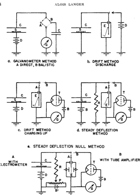
3.2.8. Detecting Devices. Galvanometers: T h e saturation current pro
duced in t h e ionization chamber can be measured b y galvanometers, electrometers, a n d electron t u b e amplifiers. Only with strongly active sample a n d t h e most sensitive galvanometers (10~1 2 a m p . / m m . ) can a direct measurement of current be carried out (Fig. 4a). Photoelectric amplification a n d t h e use of a second galvanometer does not improve this condition in t h e region of radioactive measurements encountered in tracer technique. Ballistic discharge of a condenser through t h e galva
nometer is slow a n d complicates t h e technique. Greater sensitivity can be obtained b y t h e following i n s t r u m e n t s .
Electrometers: I n electrometers a charged body moves u n d e r the influence of an electrostatic field of repulsion or attraction, until the restoring force, which m a y be gravity, elastic tension, or torsion, balances t h e electrostatic force. T h e new equilibrium position is an indication of t h e acting forces.
T h e energy (W) of a conductor with a capacity C, charged t o a poten
tial (V) is W = iCV2. Since t h e restoring energy at equilibrium acting against t h e charged body is in t h e first approximation given b y W = Kp2, where ρ is t h e displacement of t h e moving p a r t , t h e new position indi
cates t h e potential which t h e body has acquired.
Electrometers can be divided into t w o classes. Those operating by their own repulsion in a grounded case are called electroscopes. I n t h e electrometers proper t h e moving body is deflected in an artificially created electrostatic field. T h e actual construction of t h e various elements is so diverse t h a t no generalized detailed description can be
given.
The gold leaf electroscope, which played an i m p o r t a n t role in the early days of radioactivity, is not used any more as a measuring instru
ment due t o t h e irregular jumping m o v e m e n t s of t h e leaf drifting under gravitation. High capacity and low voltage sensitivity are also dis
advantageous. Present day electrometers using t h e elastic property as the restoring force have light moving parts, such as noble-metal-coated quartz fibers, 3-5μ in diameter. Quartz fibers are favored because t h e y have superior properties derived from their excellent elastic modulus and low t e m p e r a t u r e coefficient. Since the fiber weight is minute, these electrometers are not influenced by gravity and operate in almost any position. The capacity and capacity change can be kept small. The instruments are quite susceptible to air currents caused by a tempera
ture gradient in t h e envelope and are disturbed by resonance vibration.
Thermal shielding improves this condition. E v a c u a t i o n of t h e casing- reduces t h e unsteadiness of the fiber due to the effect of Brownian motion of the gas, if utmost sensitivity is desired.
Figure 3 shows a few of the better known types of electroscopes and electrometers. M a n y of them are commercially available. T h e Laurit- sen quartz fiber (30) and the Wulf bifilar electroscope are convenient to use in the drift r a t e method. The Lutz monofilar electroscope, because of its high voltage sensitivity, is recommended as a null instrument in the compensation arrangement. The arrangement of the Lauritsen electro
scope serves at the same time as the ionization chamber. The position of the fiber is determined in all the instruments b y a low power microscope with a scale in the eye piece. Care should be t a k e n t o avoid any possible charge collected on the objective lens since this lens is often quite close to the fiber, and m a y therefore cause erratic m o v e m e n t s of t h e indicator.
All the glass parts, such as the window introducing t h e light for t h e illumination of the fiber, should be covered with a conductive b u t trans
parent film of metal. For the torsion instrument light reflected from a mirror is used to indicate the twist.
When electrometers and ionization chambers are operated, t h e a p p a r a t u s should be kept dry by connection to a vessel with a good dehydrating agent. Electrometers are charged to t h e necessary potential by storage batteries, dry cells, frictional devices or best, b y rectified and stabilized current from line operated power supplies. Any desired voltage can be t a p p e d from a potentiometer. E n o u g h resistance should be inserted in series with t h e fiber (0.5-1.0 megohms) t o prevent t h e destruction of t h e fiber coating b y an accidental short to ground. T h e regulated power supply can also be used as a permanently attached potential in the charging u p and steady deflection method.
MEASUREMENT OF RADIOACTIVITY FOR TRACER APPLICATIONS 451
Q U A D R A NT B I N A N T D U A N T
f ! ] I N S U L A T O R F I B E R | | | E L E C T R O D E M I C R O S C O PE
FIG. 3. Schematic drawings of some more frequently used fiber and torsion electrometers.
Electrometer tube amplifiers: Although electrometers are relatively inexpensive, rugged, a n d easy t o operate, t h e y are being replaced b y t h e v a c u u m t u b e amplifier. Special tubes are often used where, by t h e arrangement of t h e electrodes and by careful insulation, a high grid resistance a n d low grid current is obtained. Various circuits are recom- mended t o compensate automatically for small changes in filament a n d plate voltages (41). T h e tube, together with t h e grid resistor a n d t h e
lead to the ionization chamber, is placed into an evacuated, heavy- walled iron container for shielding. T h e evacuation prevents leakage due to moisture and ionization by penetrating radiation. T o minimize a n y microphonic disturbances, shock proof mounting is recommended.
Such a mounting is shown in Fig. 2 where the electrometer t u b e is in a heavy iron t u b e suspended on a rubber shock absorber as a p e n d u l u m a n d located firmly by springs.
T h e connection of the electrometer t u b e t o t h e ionization chamber and t h e experimental methods of measurements are similar t o those used in electrostatic devices. T h e collection of a charge does not cause a mechanical movement but instead changes the potential of t h e t u b e grid, which in t u r n increases or decreases the flow of electrons from cathode to plate. In this way the primary current of t h e ionization chamber is amplified about a hundred fold. T h e resulting current can be further amplified. The o u t p u t of such an amplifier can operate rugged galvanometers, oscillographs, or pen recording instruments. If these instruments are kept under power continuously t o eliminate t h e u n s t e a d y warming up period, measurements of radioactivity can be performed rapidly with a very high precision, especially in t h e compensa- tion arrangement. Weak and strong samples can be measured b y changing the grid resistor. In the drift rate m e t h o d t h e ionization chamber is coupled to the grid by a small condenser.
3.2.4. Methods of Measurements. By connecting t h e grid of t h e amplifier or the electrostatic electrometer to the ionization chamber a new unit is formed having a total capacity d . T h e charge (Q) is given by relation Q = CXV. A change of charge of such a system can be expressed by the equation dQ = CidV + VdCi. Since t h e m o v e m e n t of the fiber in the electrometer produces only a negligible change of t h e capacity d of the system and because no change of capacity occurs with a t u b e amplifier, the t e r m VdCi can be neglected. If a current (i) is flowing through the condenser, t h e insulated system will lose its charge, and the observed time r a t e change of charge is proportional t o the change of voltage according to the equations i' = ^ = Ci · =
Ci *· T h e potential difference VQ — Vi is conveniently found by reading two positions on t h e calibrated electrometer scale or by t h e change in t h e o u t p u t current of t h e v a c u u m t u b e indicator. B y measuring t h e time (t) necessary t o cause t h e potential change (V0 — Vi) t h e current (i) can be determined. Since (t) can be measured precisely, a n d if the device is voltage sensitive, t h e m e t h o d is simple and fast. Two possibil- ities are offered by this "drift m e t h o d , " which are either to discharge t h e
MEASUREMENT OF RADIOACTIVITY FOR TRACER APPLICATIONS 453
condenser plate with t h e a t t a c h e d electrometer or to charge it u p . T h e circuits are schematically indicated in Fig. 4, b a n d c. I n b o t h cases measurements m u s t be m a d e at a potential in t h e saturation current region, so t h a t (VQ — Vi) cannot be expanded over a wide voltage range.
W i t h the discharge m e t h o d one can join t h e electrometer a n d ioniza- tion chamber firmly together, or m a k e the condenser detachable. T h e latter arrangement is recommended for g a m m a - r a y measurements: Only t h e condenser is exposed for a certain time t o t h e radiation and the charge loss is determined upon reconnecting to the electrometer circuit. I n this way the discharge occurs in t h e condenser only and not in t h e electrometer proper.
For practical measurements one has to consider t h a t t h e voltage scale, especially with fiber electrometers, is not linear. T h e drift time, there- fore, should be taken between t h e same defining marks. T h e intensity (i) can t h e n be expressed simply as ( 1/ 0 , the reciprocal of t h e time for drift between t h e chosen defining marks. T h e measurements should be started with a moving indicator, since just after charging t h e movement of t h e fiber is often erratic. All measurements are corrected for t h e background current, especially t h e leakage current. The background current m a y v a r y considerably during t h e day and frequent blank measurements should be taken, especially with weak samples.
Reliable results can also be obtained by the steady deflection method.
In this arrangement (Fig. 4d) the indicating instrument is shunted to ground b y a high resistance (R) of t h e order of 1 01 0 ohms. If a radio- active sample is brought into t h e vicinity of the ionization chamber, t h e ionization current i will build u p a potential V across t h e resistance R
t_
according t o t h e equation V = iR(l — e RC). At a time interval large enough in comparison t o RC, t h e potential will reach a constant value V = iR. T h e steady deflection on t h e indicator of tne measuring instrument at equilibrium is not influenced by the capacity of t h e system.
T h e current is therefore directly proportional t o the reading in volts on the calibrated scale. T h e value of this procedure is t h a t it can be easily changed into a null m e t h o d by compensating the current flowing in the resistor b y a current of opposite sign. This can be accomplished by a precise potentiometer, (P) (Fig. 4e) piezolectrically or with a variable radioactive compensator. Since in this case t h e indicator is not deflected, t h e electrometer can be very sensitive, especially at t h e balance point. I n case of a t u b e amplifier one does not have t o t a k e into account the corrections due t o t h e nonlinearity of the t u b e characteristics, galva- nometer readings, a n d other effects. A complete circuit for the steady deflection method, where t h e current through (R) is compensated by a
fx I I λ
AS ι Γ7 I
0 1 I l i r W
C. D R I F T M E T H O D
CHARGING U P d STEAD Y D E F L E C T I ON M E T H OD
β. STEAD Y DEFLECTION N U L L M E T H O D
FIG. 4. Idealize d diagram s o f ionizatio n chambe r connection s i n differen t method s of measurements .
C—Ionizatio n chambe r S—Sampl e
D—Variabl e potentia l suppl y fo r th e ionizatio n chambe r Ρ—Potentiomete r
G—Galvanomete r Ε—Electromete r Τ—Electromete r tub e 11—Leakag e resistanc e
Β — P l a t e potentia l fo r th e electromete r tub e
MEASUREMENT OF RADIOACTIVITY FOR TRACE Η APPLICATIONS 455
M-MEGOHMS -**OHMS T- THOUSAND I - CAPACITY IN μίd STEADY DEFLECTION NULL METHOD WITH ELECTROMETER AMPLIFIER FIG. 5. Circuit diagram of a balanced electrometer tube amplifier with potentiometer compensation and regulated power supply.
potentiometer is given in Fig. 5. T h e supply voltage is obtained from an electronically regulated pack. The variable resistors are so chosen, t h a t the circuit can be balanced t o compensate for minor drifts in t h e supply voltage. The proper operation of the instrument requires close super- vision. New possibilities are offered b y t h e dynamic condenser electrom- eter, where a mechanical vibration of one plate of a condenser produces an alternating current. The magnitude of the current depends on the impressed charge and can be easily amplified by A.C. amplifiers.
T h e Lauritsen ionization electroscope and the Wulf bifilar electro- scope with an attached ionization chamber are simple and sensitive enough t o t u r n out reliable d a t a with t h e least effort in regard t o t h e measuring technique. The sensitivity of these methods is about one alpha particle per second. Since better sensitivity and better procedures with weaker samples can be obtained with counters, t h e y are replacing almost entirely the use of ionization chambers in t h e field of applied radioactive assay. Because t h e preparation of samples and t h e necessary corrections applied to the results are similar for t h e ionization chamber as for counters, they will be discussed simultaneously in a later chapter.
3.3. Measurements by Counting (35)
3.3.1. Principle of Counters. T o explain the manner in which an ionizing particle produces discrete current pulses, large enough t o be recorded, one has to return to the interpretation of the current in the ionization chamber. At the saturation current the field gradient was strong enough to pull a p a r t all the ion and electron pairs created by the primary particle and to give t h e m sufficient energy to arrive at the elec- trodes. If the ionization chamber has a low capacity and if t h e detecting instrument is sufficiently voltage sensitive by the use of a multiple stage vacuum t u b e linear amplifier, then b y exposing the chamber t o radiation of one particle at a time, pulses will be registered. Because an apprecia- ble n u m b e r of ion pairs are formed by t h e entrance of a single alpha r a y or any other particle of high specific ionization, the voltage pulses are large compared t o t h e pulses detected at t h e arrival of a beta ray. T h e o u t p u t voltage of the amplifier is still proportional to t h e primary n u m b e r of ion pairs created in the chamber by the single particle, whose duration is given b y the time constant of the amplifier circuit. T h e resulting elec- trical pulses can be fed into a thyratron circuit to operate a mechanical register. The grid bias of t h e t h y r a t r o n can be adjusted so t h a t only pulses of preselected size are recorded. I n this way t h e "linear amplifier"
is insensitive to beta a n d g a m m a rays below a certain noise level, which can be further decreased by bending away t h e beta radiation in a mag- netic field.
MEASUREMENT OF RADIOACTIVITY FOR TRACER APPLICATIONS 457
T h e r a n d o m fluctuations in t h e circuit of t h e linear amplifier, due t o the high gain amplification, limit its use t o detecting heavily ionizing particles. This insensitivity t o beta radiation can be overcome by utilizing secondary ionization in t h e ionization chamber proper, t h u s increasing t h e n u m b e r of available ion pairs a n d therefore t h e voltage pulse. As soon as t h e applied potential is raised on t h e plates of t h e ionization chamber above a certain value t h e current carried by t h e con- denser starts to increase again. T h e liberated electrons and ions are further accelerated between inelastic collisions so t h a t t h e y possess sufficient energy, greater t h a n t h e ionization potential of t h e gas. T h e y produce, in turn, an ionization process of their own. T h e newly created electrons are again speeded u p during one m e a n free p a t h , so t h a t on collision with the electronic shells of t h e gas molecules t h e y can cause further ionization. T h u s a rapidly progressing chain reaction, an
" a v a l a n c h e " is formed. Such an avalanche produces m a n y times more ion pairs, t h a n the p r i m a r y particle.
T h e greater t h e mean free p a t h of t h e electrons or the steeper the potential gradient through which t h e electrons fall, t h e more energy t h e y acquire. T h u s in a certain range of velocities t h e y have a more favorable cross-section for t h e ionization a n d dissociation process. In this way beta rays will produce enough charges t o be detected as a short pulse.
T h e parallel plate condenser is not t h e most favorable arrangement for pulse production. An ionization chamber in t h e form of a long cylinder is preferable wherein a thin wire is stretched concentrically, a very steep potential gradient being created close t o t h e wire. Usually t h e gas in t h e cylinder is rarefied t o about 10 cm. Hg, increasing t h e mean free p a t h proportionately a n d decreasing the potential at which t h e secondary electrons acquire ionization a n d dissociation ability.
T h e wire is usually m a d e positive a n d connected t o ground with a fairly high resistance (R) as indicated in Fig. 8a. As a pulse indicator a fast a n d sensitive electrometer can be utilized, or one can use a t u b e amplifier in. which a string oscillograph is inserted in t h e plate circuit.
This arrangement at low applied voltages will work as an ionization chamber sweeping t h e electrons t o t h e wire a n d t h e ions t o t h e cylinder.
I n t h e voltage region of multiple collisions different particles will still produce different pulses. A device of this kind is known as a " p r o p o r - tional c o u n t e r " since it discriminates t h e energy content of t h e incoming radiation by t h e pulse size. Valuable as linear amplifiers a n d propor- tional counters are in nuclear physics, t h e y find only limited application in tracer work a n d will not be considered in detail. T h e same is t r u e for proportional counters filled with boron trifluoride for counting neutrons.
B y increasing t h e potential between wire and cylinder in a propor-
tional counter, the pulses will slowly approach equal size until at the so-called threshold voltage t h e pulses from any particle are almost identical. The process of internal pulse amplification is schematically shown in Fig. 13c.
Counters operated above the threshold voltage, where all pulses are of equal size are t h e Geiger-Mtiller counters proper (15). I t is observed t h a t in t h e Geiger region the current is m u c h greater t h a n would be produced by a single avalanche, and consequently it is postulated t h a t t h e ionization process m u s t t a k e place in the whole counter volume.
One explanation of why such a spreading of discharge occurs is given by t h e fact t h a t the colliding atoms are excited into higher energy states and upon returning t o their normal states emit ultraviolet photons.
These photons can liberate electrons in t h e walls a n d t h e gas b y t h e photo- and Compton effects in a n y p a r t of t h e tube, producing avalanches throughout t h e whole cylinder. Alternately t h e positive ions acquire enough energy so t h a t in t h e act of being neutralized on t h e cylinder t h e y can extract more free electrons from t h e wall t h a n they need for neutrali- zation. These electrons can act as p r i m a r y particles, t h u s spreading a n d prolonging t h e discharge.
Let us investigate t h e process t h a t terminates t h e discharge once started. A very dense concentration of ionized particles is produced close to t h e wire. Since t h e highly mobile electrons are rapidly collected on the wire, a positive sheath of ions is left behind, drifting relatively slowly to t h e cylinder. I n this way an expanding space charge envelope is created, which can lower the effective field around t h e wire to such an extent t h a t all production of secondary ion pairs is stopped. T h e space charge, therefore, causes a cessation of t h e discharge. Only after a large part of t h e positive ions are collected on t h e cylinder will t h e t u b e be restored to its sensitive condition. This mechanism of internal quenching will be especially effective if one can prevent delayed photon emission of the excited molecules and the additional electron liberation on t h e wall by the neutralization process. Certain polar organic vapors, like alcohols, acetone, esters, and m a n y others, for example, organic metallic com- pounds (23), even in quite small amounts, absorb by collision the exci- tation energy of t h e counter gas, which is dissipated as kinetic energy instead of radiation. In this way t h e creation of photoelectrons is inhibited without preventing the initial spreading of the discharge through t h e whole volume of t h e tube. Organic vapors are also absorbed on the walls of the cylinder and t h u s can retard the formation of multiple discharges caused by the liberation of more electrons t h a n the neutraliza- tion process requires. These additional electrons seem t o be the origin of t h e spurious counts, which sometimes closely follow t h e actual dis-
MEASUREMENT OF RADIOACTIVITY FOR TRACER APPLICATIONS 459
charge released by the p r i m a r y ionizing particle. T h e spurious counts cause the tube to fire with increasing frequency, not proportional to the incoming radiation. Such a state always develops at sufficiently high potentials.
There is still another effective mechanism which will terminate the discharge. At the threshold voltage the pulses created b y different particles become equal in size. This is the voltage where avalanches start t o spread t h r o u g h o u t t h e whole t u b e . However the actual counting is done at a higher operating voltage. T h e difference between the thres- hold and operating potential is called overvoltage. If after a discharge has started, one rapidly lowers t h e potential across the tube, below the threshold voltage, the spreading of avalanches terminates a n d t h e dis- charge is interrupted. Such a lowering of potential can be accomplished if the bleeder resistance to ground (R) is made high enough so t h a t R > -j- I n this way the potential across the counters will be a u t o m a t i - cally reduced below t h e starting potential as soon as enough charges are collected t o produce a current (i). Normally, to obtain a potential drop of t h e order of t h e overvoltage, t h e resistance R has to be about 1 01 0 ohms.
Figure 13a, indicates a typical pulse created by a particle entering t h e counter as viewed on an oscilloscope with linear synchronized time sweep.
T h e wire collecting t h e electrons acquires t h e potential Vo r a t h e r sud- denly. After t h a t t h e pulse is dying, because t h e charge is leaking off
t_
t h r o u g h R. T h e potential (V) at a time (t) will be given b y V = V0e R C where C is the capacity of t h e circuit. T h e recovery time (tr) necessary t o obtain a small enough potential (V) to restore the circuit to operating conditions will therefore depend on RC. Because R is large, U is also long (around 10~3 second) and counters quenched in this way are called slow counters. A sudden lowering of the potential can be achieved m u c h more quickly b y an electron t u b e arrangement.
T h e counters filled with an organic vapor are internally quenched and have a recovery time of t h e order of 10~5 second. T h e y are called fast counters. T h e resistance R can have a much lower value. T h e dis- a d v a n t a g e of counters filled with an organic vapor is t h a t the organic compounds are dissociated into fragments by the discharge mechanism.
T h e original filling is slowly used u p with each count, changing t h e counter characteristic a n d giving t h e counter a lifetime of the order of 108 to 1 01 0 counts. Small counters, in which t h e gases would be used u p more rapidly, can be connected t o a large gas storage vessel (51).
8.8.2. Construction of Counters. T h e counter constructions are not restricted t o t h e cylinder and wire t y p e . A n y arrangement of electrodes
where a steep potential gradient can be maintained close t o one electrode will show self-quenching properties. Some constructions are indicated in Fig. 6.
The ball t y p e counter consists of a small ball in t h e center of a hemi
sphere. A sharp point against a flat plate is usually called t h e point
mm υ
BALL COUNTER POIN T COUNTER
Ϊ/////////Λ
>;
W////////S
>CYLINDER-WIRE COUNTER CONCENTRIC CYLINDER COUNTER
P L A T E - W I RE PARALLE L P L A T E
C O U N T ER C O U N T E R
INSULATOR SENSITIV E VOLUME
FIG. 6. Different types of counter constructions.
counter. These arrangements actually furnished t h e first demonstration t h a t it is possible t o count individual alpha particles. T h e y can be operated at atmospheric pressure a n d t h e particles enter t h e counter volume through a small hole in t h e larger electrode or through a wire gauze window. Their disadvantage is t h e r a t h e r small sensitive volume and insensitivity t o b e t a and g a m m a radiation.
W i t h t h e development of electronic quenching circuits almost a n y
MEASUREMENT OF RADIOACTIVITY FOR TRACER APPLICATIONS 461
arrangement of electrodes can be utilized for counting, and one finds counters constructed as concentric cylinders, parallel plates, plate a n d a wire, a n d other forms. These and the concentric cylinder counter h a v e the a d v a n t a g e of a large sensitive volume and a wide area for t h e pene- tration of t h e radiation. T h e cylinder wire counter is t h e best developed a n d most commonly used. E q u i p m e n t like t h e Greinacher spark counter (14), the scintillation counters a n d t h e crystal counter show considerable promise, b u t m u s t be considered of scientific interest only at this t i m e . T h e basic design of t h e Geiger-Muller cylinder-wire counter can be widely varied a n d a d a p t e d t o a n y problem of radioactive measurement.
I n t h e determination of penetrating radiation, particularly g a m m a rays, cylinders of heavy metals, like copper, cobalt, molybdenum, a n d platinum, with sufficiently thick walls are recommended, so t h a t optimal yield of photo a n d recoil electrons or pair production with g a m m a rays above 1 M e v is obtained in t h e sensitive volume (4). Screen wire cylinders of heavy metals will increase t h e g a m m a ray sensitivity because of their large surface (13). A counter with cylinders m a d e of material m a d e radioactive b y neutron irradiation, like silver, can be used for neutron detection. T h e glass used in neutron counters should not contain boron because this element is a good neutron absorber. T h e cylinders are either completely inclosed in a glass envelope (Fig. 7a) or are sealed t o glass ends if glass sealing metals are used for the construction (Fig. 7b). T h e practice of fastening hard rubber ends by wax t o hold a n d insulate t h e central wire is now generally abandoned because such counters cannot be outgassed at elevated temperatures and because the wax absorbs t h e filling gas, changing t h e characteristic of t h e counter on storage. T h e diameter of t h e cylinder can v a r y from millimeters (8) t o several centimeters; the length being at least four to five times t h a t of t h e diameter. T h e inside of t h e solid t u b e should be smooth with ends slightly flared out t o eliminate end effects. T h e metal is often treated for chemical stability and low photo emission. The surface should not change with time by the vigorous reactions taking place in the counter during each discharge. For t h a t reason when employing a copper anode, a bright copper electrode is used with a hydrogen mixture. W i t h mix- tures of oxygen, on t h e other hand, the cathode is oxide coated. Iron or tungsten wire with a diameter from 1 t o 30 mils is used as the central electrode. T h e diameter of t h e wire has an effect on the starting poten- tial of t h e counter. T h e wire is preferably t a k e n out at b o t h ends of t h e counter t u b e . T h e counter, as a whole, is outgassed for several hours a t 300°C. or higher. Before filling the wire is flashed for several seconds under v a c u u m to white heat, b y passing current t o release occluded gases, b u r n off all dust a n d grease, and smooth its surface. T h e wire is kept
i
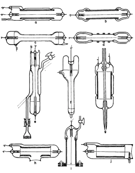
FIG. 7. Commonly userd Geiger counter constructions.
a. Heavy solid cylinder glass envelope counter b. Solid cylinder with sealed on glass ends counter c. Thin walled glass envelope counter
d. Thin metal cylinder counter
e. Thin walled liquid-jacket pipette counter f. Thin walled dipping counter
g. Capillary wire counter h. Front window counter
i. j . Side window or bell type counters.
MEASUREMENT OF RADIOACTIVITY FOR TRACER APPLICATIONS 463
stretched by a small tungsten spring a t one end a n d t h e weldings are pro- tected b y glass sleeves. These sleeves should shield a n y sharp points resulting from t h e welding b u t should not be extended too close t o t h e sensitive volume. T h e glass might become charged, distort t h e field, a n d cause spurious counts. Terminals for t h e wire a n d cylinder are t a k e n t o t h e outside b y tungsten seals, or glass sealing alloys. T o obtain good seals a n d mechanical strength a combination of glasses, like Nonex a n d Pyrex, m a y be used in t h e construction. T h e outside ends of t h e counter are covered with a film of wax b y dipping into molten ceresin, t o insure high leakage resistance even in h u m i d weather. A connection for sealing t o t h e v a c u u m a n d filling system is also attached.
M a n y fillings are recommended in t h e literature t o obtain best performance. P u r e hydrogen, dry air, 9 6 % argon with 4 % oxygen or helium are used in slow counters. Argon saturated with ethyl alcohol at 0°C. with 1 cm. H g amyl acetate or other polyatomic vapors perform satisfactorily in fast counters. A total pressure of approximately 10 cm.
H g gives favorable operating potentials. A good procedure is t o test t h e counter during t h e filling stage before sealing off. T h e helium filled counter at atmospheric pressure has m a n y advantages and will probably be more widely used in t h e future.
T o measure low energy b e t a rays an envelope thin enough t o permit t h e penetration of t h e radiation into t h e sensitive volume is necessary, for this t h e walls of t h e metal t u b e are ground t o t h e thinnest cylinder t h a t can withstand t h e outside pressure (5). T h e cylinder can be reinforced b y heavier ribs (Fig. 7d). T h e particles can also be a d m i t t e d through a very thin walled glass envelope. T h e solid cylinder is replaced b y a screen or b y a thin conducting layer of colloidal carbon, wet deposited silver, or copper, or other v a c u u m evaporated metal (Fig. 7c). For better operating conditions it is recommended t h e glass be covered on t h e outside of t h e sensitive volume with a conducting layer. Another useful t y p e is t h e side window (Fig. 7g) a n d front window counter (Fig.
7h). T h e former is known as a bell t y p e counter since it has a very thin m e m b r a n e of glass, mica, aluminum, or beryllium stretched across one side of t h e cylinder.
I n t h e front window counter t h e radiation enters through a hole in t h e cylinder, in t h e bell t y p e it passes axially. I n this w a y a large sensitive volume for radiation is obtained. T h e glass m e m b r a n e can be m a d e b y an indrawn glass bubble, or better and more uniformly b y sealing a p a r t of a large thin glass bubble t o t h e softened end of t h e counter t u b e . Windows of mica or metal foils can be cemented t o t h e cylinder b y a Silicone plastic or clamped between lead or tin gaskets (10, 53). Large windows can be supported b y a grid. T h e cylinder m a y be t h e metal
envelope of t h e counter (Fig. 7i), or a solid metal cylinder in t h e glass t u b e (Fig. 7j). Sometimes t h e other end of the central wire is not brought t o t h e outside b u t terminated with a small glass ball t o prevent an irregular potential gradient due t o a sharp point. T h e disadvantage of this construction is t h a t t h e wire cannot be easily flashed and t h a t vibrations can cause instability in operating such a counter tube.
Very thin glass, mica, and metal windows can be used if the counter is filled with helium at atmospheric pressure (17). In this case t h e m e m b r a n e acts as a barrier for t h e gas only, without the necessity of withstanding any pressure. B y this arrangement even very soft beta rays can penetrate into t h e sensitive region, without need of introducing the sample directly into t h e counter. For ordinary counter work t h e diameter of the cylinder is around 1 to 3 cm. with a glass m e m b r a n e thickness of 0.02 m m . or mica windows as thin as 1.5 m g . / c m .2
8.3.8. Auxiliary Equipment. E a c h counter requires a high voltage supply. T h e potential should be continuously variable from about 300 volts to about 2000 volts to meet t h e operating range for different coun- ters. T h e rectified current from t h e transformer should be stabilized either by a set of neon stabilizing tubes or b y a vacuum t u b e circuit.
With counters t h a t have flat plateau small fluctuations can be tolerated.
Since only a relatively small current is drawn from t h e circuit by t h e counter, inexpensive neon sign transformers with half-wave rectification prove satisfactory. Low voltage supplies can be regulated by standard gas filled tubes.
I n practice one does not rely on the self quenching property of fast counters alone, b u t uses an external extinguishing circuit. T h e basic high resistance quenching circuit is not used frequently because it has a low resolving power. Instead, electronic quenching circuits are pre- ferred for extinguishing t h e gas discharge as soon as it is established t o a certain degree. Such circuits, which depend on t h e action of t h e collected charges on t h e grid of a v a c u u m tube, shorten t h e original discharge pulse and speed u p t h e obtainable counting rate. T h e y also amplify and broaden the pulses t o a more uniform size for simpler further amplifica- tion or recording.
In the commonly used quenching circuits the electron t u b e represents a rapidly adjustable rheostat automatically controlled by the counter t u b e either to short circuit the counter b y decreasing its resistance, or by increasing the resistance and hence cut off t h e counter t u b e from the high voltage.
T h e first principle is utilized in t h e Neher-Harper circuit (37), (Fig.
8b). T h e t u b e is negatively biased and therefore in a nonconducting s t a t e . Connected parallel t o the counter tube, it represents a very high
* MEASUREMENT OF RADIOACTIVITY FOR TRACER APPLICATIONS 465 a. 6 E I 6 E R - C 0 U N T ER ARRANGEMENT
CM. T U B E „
A - W I TH ELECTROMETER, B - W I TH TUB E D E T E C T I ON b. Q U E N C H I NG CIRCUITS
N E H E R - H A R P ER " NEH E R-PICKERING
c. REIC H SCALING C I R C U IT
FIG. 8. Diagram of Geiger counter circuit components.
resistor. As soon as a pulse is created, t h e counter cylinder becomes more positive b y t h e collected positive ions, the grid potential of Τ is raised, a n d a plate current starts t o flow. I n this state t h e v a c u u m t u b e repre
sents a rather low resistance a n d an appreciable potential drop will be established across t h e counter tube, which quenches t h e discharge. As soon as t h e positive charge leaks from the grid through t h e resistor R, t h e electron t u b e again becomes nonconducting, t h e high voltage is re-estab-
lished across t h e counter tube, and t h e counter is ready for t h e next count.
I n t h e Neher-Pickering circuit (38) (Fig. 8b) t h e t u b e is normally conducting and functions as a low resistor. T h e high voltage is passing through t h e t u b e giving t h e grid and t h e counter wire almost t h e same potential as t h a t of the cathode. W h e n a pulse arrives, t h e grid becomes negative b y t h e collected electrons on t h e center wire, t h e t u b e becomes nonconducting and t h e high voltage supply is practically disconnected from t h e counter t u b e . Again, when t h e charge leaks off t o ground through Ri and R2 t h e previous active condition is restored.
Several modifications of these t w o basic principles of pulse extin
guisher h a v e been described (1). Multivibrator circuits using amplifica
tion and positive feedback have been constructed (16, 47). I n t h e actual circuits pentodes are usually used. For tracer work t h e Neher-Pickering circuit is given preference because in this a n d similar circuits t h e cylinder of the counter t u b e is at ground potential. T h e cylinder acts as a protecting shield for t h e charged wire reducing disturbances when t h e counter is handled with t h e samples in t h e working condition. Such an arrangement is safer t o operate.
The pulses from t h e quenching circuit can be directly fed into the recording circuit. Mechanical registers based on t h e movement of a ratchet actuated b y a v a n e a t t r a c t e d b y an electromagnet are relatively slow, not exceeding about 100 pulses per second for evenly spaced pulses, unless special precautions are t a k e n (36). T o increase t h e counting r a t e a scaling circuit is introduced (52). Such a circuit suppresses a definite n u m b e r of pulses before reaching t h e mechanical recorder. Since scaling circuits are very fast, t h e resolving time of t h e counter system can be greatly improved. T h e function of such a circuit scaling b y a factor of two is shown schematically in Fig. 8c (42).
T h e circuit has two stable conditions. Either t u b e A is conducting and tube Β nonconducting or the reverse. T h e suppressor grids as well as t h e control grids control t h e action of t h e tube, a n d t h e circuit responds only t o negative pulses. Suppose t u b e A is initially conducting and Β nonconducting and a negative pulse is impressed at t h e control grid of tube A through a suitable condenser C. T h e current in t u b e A will decrease, the plate voltage will rise, and these changes are transmitted very rapidly through condenser C2 t o t h e suppressor grid of t u b e Β and then held at their respective potentials through t h e resistance R. Since the suppressor grid of t u b e Β becomes more positive, this t u b e will become conducting, t h e voltage across it will fall, and in a similar way as before t h e potential of t h e suppressor grid of t u b e A decreases t o such an extent t h a t t u b e A is now nonconducting. Since b o t h tubes have
MEASUREMENT OF RADIOACTIVITY FOR TRACER APPLICATIONS 467
their control grids connected together a second negative pulse will change t h e situation back to t h e original state, t h a t is, t u b e A becomes conduct
ing and Β nonconducting. W h e n this happens a negative pulse whose potential moves u p or down each time t h e circuit trips is generated at point K. Through a condenser this pulse is t r a n s m i t t e d t o t h e next stage. T h u s one negative pulse is t r a n s m i t t e d t o t h e o u t p u t for every two pulses entering t h e circuit.
A b a t t e r y of such circuits works in seals of 2n, where η is t h e n u m b e r of identical stages used. E v e r y 2nd, 4th, a n d 8th pulse is passed and recorded. Scaling stages u p t o several t h o u s a n d have been constructed.
Interpolation of single counts, b y means of t h e sequence of neon lamp indicators is incorporated. Recently ring circuits with a scale of 10 have been constructed (43). Such a decade scale reduction is more convenient for a large n u m b e r of recordings. I n order t h a t t h e scaling circuit works properly t h e pulses from t h e extinguishing circuit are first converted b y feeding t h e m into a triode t o change their sign a n d t h e n applied t o t h e grid of a t h y r a t o n . T h e grid bias of t h e t h y r a t r o n acts as a discrimina
tor, passing only pulses of one predetermined size, a n d t h e t u b e charac
teristics cause all t h e pulses t o be sharpened a n d equalized. T h e o u t p u t of the circuit are identical pulses equal in number to those from t h e counter tube.
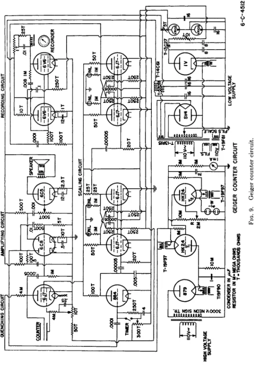
T h e o u t p u t from t h e scaling circuit are voltage pulses. I n order t o operate a mechanical recorder a transformation to current pulses m u s t be made. This is accomplished b y special circuits. A complete count
ing circuit using t h e described basic elements is shown in Fig. (9).
If pulses of uniform size a n d shape charge a condenser, which, after reaching a certain potential, trips a t h y r a t r o n t u b e and then is completely discharged, the t h y r a t r o n pulse can also operate a mechanical recorder.
I n this way large scaling numbers can be obtained, adjustable b y t h e capacity of t h e condenser or b y t h e pulse size used. If t h e charged con
denser bleeds through a resistor and a galvanometer, t h e reading of t h e meter is proportional t o t h e average counting rate with a time constant of 2 RC seconds. Continuous graphical recording of t h e radioactivity is possible. T h e circuit is especially valuable for high counting rates
(9, 25).
Recently properly designed counters and counter circuits have appeared on t h e market. W h e t h e r one uses self-built counter equipment or commercial models t h e counter t u b e a n d circuit have t o be tested in their performance before use in any investigation.
3.8.4.. Test of Counting Equipment. I n this section some of t h e important tests t o establish t h e reliability of t h e instrument will be men
tioned (26). First t h e characteristic curve of t h e counter m u s t be deter-
CONDENSER IN* - LOW VOLTAGE RESISTOR ^ί:^^^^ GEIGER COUNTER CIRCUIT SUPPLY 6-C-45I2 FIG. 9. Geiger counter circuit.