A P P L I C A T I O N OF SIDEBAND F O L D I N G T E C H N I Q U E S T O T H E NAVIGATION S A T E L L I T E SYSTEM
1 2 James W. Crooks J r . , Robert C. W e a v e r , and M a l v i n M . Cox
General D y n a m i c s / A s t r o n a u t i c s , San Diego, C a l i f · ABSTRACT
A satellite navigation system is proposed employing side- band folding techniques f o r m e a s u r i n g accurately t i m e - c o r r e - lated range and/or range rate b e t w e e n Earth and a satellite of k n o w n ephemeris to determine t h e p o s i t i o n of a n a v i g a t i o n station on the surface of Earth* T h e u s e of sideband f o l d - ing combined w i t h h a r m o n i c a l l y related V H F and m i c r o w a v e carrier frequencies provides m a x i m u m accuracy w h i l e conserv- ing t r a n s m i t t e r p o w e r . Sideband folding, although d i s c a r d - ing some of the received signal p o w e r , permits reception of high m o d u l a t i o n frequencies for p r e c i s e range m e a s u r e m e n t in a v e r y narrow b a n d w i d t he Harmonically related V H F and m i c r o - w a v e carrier frequencies provide t h e high ranging accuracy of a m i c r o w a v e carrier, w i t h its m i n i m a l susceptibility t o i o n o - spheric p r o p a g a t i o n phenomena, and permit narrower m i c r o w a v e receiver bandwidths by aided tracking of t h e m i c r o w a v e f r e - quency » Narrow bandwidths allow use of lower transmitter p o w e r s , particularly of interest in satellite transmitters*
Economy of RF power t r a n s m i s s i o n and generation is enhanced by using t h e VHF carrier frequency f o r noncritical satellite t r a n s m i s s i o n s , including m i c r o w a v e acquisition d a t a . P r o - visions are m a d e for l e s s e r accuracy m i c r o w a v e Doppler n a v i - gation without n a v i g a t i o n station t r a n s m i s s i o n s0
INTRODUCTION
T h e Navy Transit satellite navigation system represents a m a j o r breakthrough in the state of t h e art of naval n a v i -
gation* Accurate d e t e r m i n a t i o n of the p o s i t i o n of a n Presented at A R S G u i d a n c e , C o n t r o l , and Navigation
Conference, Stanford, Calif., Aug. 7-9, 1 9 6 1 . This w o r k w a s sponsored by General Dynamics/Astronautics«
1E n g i n e e r i n g Staff S p e c i a l i s t .
^Design Specialist,
^Design Specialist,
511
observer from an analysis of Doppler shift, w i t h t i m e and orbital parameters k n o w n , fills a m u c h needed all-weather world w i d e navigation system r e q u i r e m e n t0
Certain features are discussed w h i c h , w h e n added to t h e transit-type n a v i g a t i o n system, w i l l improve its already good characteristics. T h e s e improvements are reduced computation, reduced observation t i m e , and increased a c c u r a - cy. T h e method of transmission of ephemeris and time d a t a necessary for the position solution is not d i s c u s s e d . It is assumed that these data are transmitted w i t h the required accuracy, w h e t h e r received via the transit carrier or by a separate communication link*
REVIEW OF TRANSIT T E C H N I Q U E
Some of the pertinent characteristics of the Transit satellite system, described in Refs* 1 and 2,are reviewed hereο A Transit*type satellite transmits a signal that is controlled by a very stable crystal o s c i l l a t o r . T h i s signal is received at a navigation station and the f r e q u e n c y
compared w i t h a second stable oscillator in t h e navigation station» The difference in the frequencies of t h e two is recorded as a function of t i m e .
T h e primary factors that influence the frequency recorded a r e : l ) the difference b e t w e e n the frequency transmitted by the satellite and t h e frequency at the reference oscillator of the n a v i g a t i o n station; 2 ) the D o p p l e r frequency shift due to the rate of change in the l i n e of sight d i s t a n c e between the satellite and t h e navigation station; and 3 ) the influence of the ionosphere o n the signal t r a n s m i s s i o n . The desired output information is latitude and longitude of the navigation station. The computational process involved m a y be described as establishing a m a t h e m a t i c a l m o d e l of the received frequency difference v s . time relationship to be expected as a function of l a t i t u d e and l o n g i t u d e , and t h e n solving this m o d e l to get a best fit solution t o t h e input d a t a . Ionospheric effects on t h e d a t a are significant enough to warrant discussion u n d e r a separate heading,
A further look into the computations w i l l aid in u n d e r - standing the actual problem in m o r e d e t a i l . The required inputs, both functions of t i m e , are l ) satellite position and 2 ) a series of observed frequency d i f f e r e n c e s between the satellite signal, as received at the station, and a frequency reference at the station. The satellite p o s i t i o n as a f u n c t i o n of time can be computed from an ephemeris
established p r i o r t o time of u s ec Both ephemeris and time information can be relayed to the navigation station via the satellite or by other radio relay, depending on the system design* T h e m e a n s of relay of this data is not important t o t h e principle of o p e r a t i o n of the system but m a y be important from o p e r a t i o n a l considerations* The series of observed frequency differences m a y actually b e derived from m o r e than one signal in order to reduce effects of the ionosphere and a l s o , a s proposed in this paper, to get better resolution* Limited smoothing m a y be applied to reduce noise on t h e measurement* Care must be t a k e n not to distort the data needed f o r solution of t h e m a t h e m a t i c a l m o d e l by
excessive smoothing* Any corrections for ionospheric effects on propagation m u s t be accomplished before entering these m e a s u r e m e n t s into the m a t h e m a t i c a l model©
Although only latitude and longitude output data are n e e d - ed, other terms in t h e error m o d e l must be evaluated to solve the problem. T h e r e are two t e r m s of principal
importance: l ) the term that accounts f o r the uncertainty of the d i f f e r e n c e b e t w e e n the satellite transmitter frequency and the reference frequency at t h e n a v i g a t i o n station; and 2 ) the term that has to be evaluated which corresponds to a Doppler i n t e g r a t i o n constant. (This m a y be considered to be a range zero s e t . ) T h e a c c u r a c y of d e t e r m i n a t i o n of t h e s e terms is a f u n c t i o n of a number of factors including:
1 ) T h e exactness of the representation of the physical problem ty t h e m a t h e m a t i c a l m o d e l . Approximations m a y h a v e b e e n m a d e to simplify t h e m a t h e m a t i c s or to a l l o w a
solution because there is insufficient information to
evaluate secondary t e r m s . T h e validity of the assumption of no frequency drift over the observing intervals m a y also be questionable*
2 ) T h e amount of noise in t h e m e a s u r e m e n t s . Noise is h e r e defined as random errors in the observations w h i c h include such sources as quantizing (least c o u n t ) errors, miscount errors, and random p r o p a g a t i o n fluctuation errors*
3) T h e accuracy of the k n o w l e d g e of the constants in the m a t h e m a t i c a l m o d e l . Such things as inaccuracy in t h e
satellite orbit d a t a , time d a t a , absolute frequency, or knowledge of E a r t h1s shape enter in here*
4) T h e strength of the solution. This deals w i t h t h e degree to w h i c h variables can be separated and is a function of t h e geometry of the particular satellite path
being observed with respect to the navigation station location and the interval of observâtion*
The accuracy of the navigation solution is directly depend- ent on the accuracy of evaluation of terms 1 and 2 . Ref· 1 provides an estimate of the overall navigation errors to be expected from the sources described a b o v ee
IONOSPHERIC EFFECTS
In the transit system, two frequencies are employed in order that a compensation can be made for the effects of ionosphere on the transmission of VHF signals. At frequencies above 100 m c , ionosphere causes the velocity of propagation to differ from the velocity of propagation through a vacuum by an amount that is, to a close approximation, inversely pro- portional to the frequency squared. Thus, using higher frequencies reduces the ionospheric effect on the data. By using two frequencies in the VHF region which are harmoni- cally related, the major portion of the influence of the ionosphere can be compensated. However, some residual will be present which limits system accuracy.
Another approach to the ionospheric problem is to use a higher microwave frequency. This will further reduce the effect of the ionosphere and also increase the resolution of the system because more cycles are present to be counted.
The argument against increasing the frequency is that several factors make it more difficult to get sufficient signal transmitted from the satellite to be received and used by the navigation station. First, it is more difficult to produce power in the microwave regions than at VHF
frequency regions, with solid state transmitters of the type desirable in satellites. Second, the transmission losses between the satellite and the ground station increase at higher frequencies. Third, the bandwidth required to track the Doppler information obtained in the microwave signal is greater than than required at the VHF frequency, since the Doppler shift is greater* This bandwidth is dictated by the second derivative of the Doppler information, when a conventional tracking filter is used.
The difficulties of signal transmission and reception at microwave frequencies are illustrated in Figs. 1 - 4 · For practical antenna gains, as shown in Fig. 1, the total transmission loss as a function of frequency is shown in Fig. 2 . The corresponding signal/noise ratios of the in- dicated power outputs and receiver noise figures and a
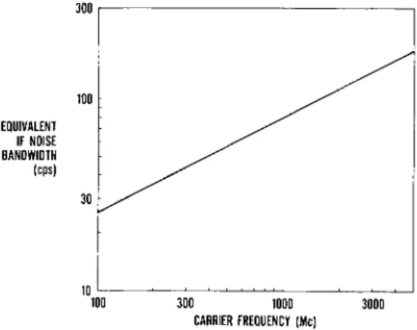
receiver bandwidth of 1 kc are shown in F i g . 3 . The actual equivalent IF noise bandwidths required to track a satellite in a 400 η m i l e orbit is shown in F i g . 4 · A type~2 servo w i t h a m a x i m u m lag of 0.2 radian w a s used for this g r a p h . The resulting signal/noise ratio in t h e tracking f i l t e r is shown in F i g . 5 . This curve is indicated as "S/N without aided tracking.11 Since about 15- d b signal/noise ratio is required to satisfactorily t r a c k , it is apparent that some improvement is necessary if tracking at 3 kmc is to be achieved.
P A S S I V E DOPPLER SYSTEM
The technique discussed in t h i s paper proposes that the satellite transmit two f r e q u e n c i e s . One is a frequency similar to one of the t w o used in the VHF transit system.
The other, instead of being a second h a r m o n i c , is a m u c h h i g h e r order harmonic in t h e S-band region. The m i c r o w a v e frequency can be produced in a satellite by m e a n s of presently available varactor m u l t i p l i e r s in a n a l l solid state t r a n s m i t t e r . (See R e f . 3 and 4o) T h e state of t h e art has advanced to t h e point w h e r e a power output l e v e l of about 100 m w at 3000 m c is feasible w i t h a transmitter i n - put power of 2\ w . This power is in t h e region of power that might reasonably be m a d e available in a small satellite for continuous operation using solar cells and storage battery s o u r c e s . P o w e r outputs for a transmitter w i t h this input power are shown over the frequency region of interest in F i g . 6.
The difficulty in tracking this increased information rate of m i c r o w a v e Doppler in the n a v i g a t i o n station m i c r o w a v e receiver is overcome w i t h aided tracking in the proposed system, as shown in Fig. 7« The VHF Doppler information is used as a n input to "buck out11 the m a j o r Doppler effect at the m i c r o w a v e f r e q u e n c y . The output frequency, determined b y VHF m e a s u r e m e n t , is multiplied by the ratio "N" b e t w e e n the VHF carrier and the m i c r o w a v e carrier. This frequency, which contains D o p p l e r information, is subtracted in a m i x e r from the information present on t h e m i c r o w a v e channel*
As the frequency shift and rate of change of frequency shift are substantially reduced at the m i x e r output, t h e signal can be tracked in a m u c h narrower f i l t e r . Very w e a k signals received in the m i c r o w a v e channel can consequently be
tracked without requiring undue m i c r o w a v e antenna g a i n . After t h e signal has passed through this narrow tracking filter, it is combined w i t h t h e frequency derived by m u l t i - plying the VHF signal to produce a composite measurement
515
that contains frequency variations equivalent to the Doppler information on the microwave carrier alone. Thus the signal has been passed through a narrower band filter than would be feasible without this technique©
An alternate technique for aided frequency tracking would be to use computer derived information to replace the freq- uency information generated from the VHF signal. This tech- nique can be used with the proposed satellite to allow
passive microwave Doppler tracking without the use of the VHF signal and would allow a submarine to project a very small antenna above the water to make the required observations©
This antenna could consist of a dielectric rod about 1 in.
diam, and 18 in. long extended on a periscope type mount above the water and pointed approximately at the satellite.
Some means of using very narrow filter bandwidths is required to make microwave Doppler practical© Aided track- ing provides a good solution to this problem. The result of a computation for the frequency of 3000 mc with aided track- ing is shown in Fig. 5ο Since the VHF aided tracking tech- nique provides a straightforward method of frequency ac- quisition as well as tracking, it is recommended for most navigation station applications. On submarines, addition of a computer aided tracking and acquisition mode is justified©
Under conditions in which possibility of surface detection must be minimized, this addition allows navigation while
exposing only the microwave antenna*
A summary of the passive tracking portion of the proposed system is in order. A microwave signal will be transmitted from the satellite instead of one of the VHF signals such as now used in transit. The other VHF signal will be used for aided frequency tracking and aided frequency acquisition of the microwave signal. The microwave signal, by providing more Doppler cycles and less ionospheric error than a VHF signal, will allow improvement in accuracy, even when used in the passive mode. These signals serve additional functions allowing active mode operation.
FEATURES OF ACTIVE MODE
An active mode is incorporated in the proposed system to give a means of evaluation of terms 1 and 2 of the mathe- matical model described above to a higher accuracy than
possible with the passive system. This simplifies the
conputation, reduces the observation time needed, and provides
greater accuracy. It should be recognized that, to an extent,
these are tradeoff improvements in that not all improvements can be achieved to the fullest extent simultaneously
eHow- ever, all can be achieved simultaneously to a large extent*
A significant improvement possible from the proposed active mode is that the application of this technique at the
stations used for establishing the satellite ephemeris improves the accuracy of all navigation station measurements whether or not they operate in the active mode»
ACTIVE DOPPLER OPERATION
The active mode would provide both two-way Doppler (active Doppler) and two-way ranging (active ranging) without compro- mising the operation of the satellite with navigation
stations operating in the receiving (passive) mode only* The active Doppler measurement described in this section provides the method of accurately evaluating term 1 in the mathemati- cal model.
Frequency acquisition by the navigation station is relatively easy despite the narrow system bandwidths. At all times the satellite is transmitting a VHF signal and a harmonically related microwave signal. The navigation station initiates tracking of the satellite VHF signal, followed by tracking of the microwave signal, as described in the passive Doppler discussion. After the tracking filters are operating on both signals, a measurement of the frequency difference between the received satellite signal and the frequency reference at the navigation station is made. A transmitter control signal is generated from the measurement. This causes the transmitter in the navigation
station, while still inoperative, to be tuned from its reference frequency to a new frequency opposite in direction to the apparent Doppler frequency shift, in the received signal. Manual adjustment is provided for trimming out the effects of any known frequency drifts between the satellite transmitter frequency and the navigation station reference frequency. On operator command, the navigation station transmitter is activated for a short burst transmission*
A simplified block diagram of the proposed active system is shown in Fig. 8. The microwave signal of frequency fi is transmitted to the satellite. There it passes from the antenna through a duplexer (not shown) to a microwave mixer.
About 1/2 mw of the satellite transmitter power signal of frequency Î2 is also injected into this mixer to act as a local oscillator signal. At the output of the mixer the difference between the received and transmitted frequencies
517
appears and is fed into a narrow band intermediate frequency amplifier. After amplification, this difference frequency signal is transmitted as a subcarrier fa<j on the VHF carrier f^ to the navigation station. After demodulation and filter- ing, it is subtracted from the microwave receiver and micro- wave transmitter difference frequency. The resulting signal gives the normal two-way Doppler information as if trans- mission had been both ways at the frequency f]_ of the navigation station transmission. This can be expressed as follows :
f
d « f
±- f
2(l-D) - fm
3(l-D) [1 ]
fm
3= f^l-D) - f
2[ 2 ]
f
d= f
λ- f
2(l-D) - [f^l-D) - f
2] (1-d) [3 ]
= 2f
1d - f D exp 2 [ 4 ]
Since D «< 1
Ώχΐά/2ΐλ
f^ = carrier frequency of the navigation station transmitter
f^ = carrier frequency of the satellite microwave transmitter
fm^ = modulation subcarrier on the satellite microwave transmitter
f^ = measured Doppler frequency
D = Doppler coefficient = range rate/velocity of transmission
Since the passive frequency measurement shown in Fig. 7, but omitted from Fig
08, can be carried out simultaneously with the active determination of the Doppler frequency, the difference between the navigation station reference oscillator and satellite transmitter can be accurately determined.
Since the transmitter at the navigation station is pre-
tuned to account for Doppler shift, the bandwidth of the
satellite narrow band IF amplifier need only be great
enough to allow for a signal detuning of little more than
twice the uncertainty in frequency difference between the
satellite transmitter and the navigation station frequency
reference. For example, a relative frequency accuracy of
10-' should easily be attained, since even passive measure- ments allow this difference to be computed, and drifts
between observations should be very low. At S-band this would correspond to a plus or minus 600 cycle detuning allowance. Thus a receiver bandwidth as narrow as 1.5 kc could safely be used.
Several features were omitted from the diagram and explana- tion for reasons of simplicity. A squelch circuit is employ- ed to shut off the modulation signal when no signal is being received. A second mixer is also used. It is supplied with a subharmonic from the transmitter multiplier chain as the second L0 signal and passed into a second IF amplifier before feeding into the VHF transmitter. This frequency offset is accounted for in reduction of the data.
ACTIVE RANGING
In addition to measuring the Doppler frequency in an active manner, the proposed system also provides means for measur- ing the range by measuring the phase delay of modulation frequencies. This provides data for determination of mathematical model term 2 (range zero set).
This active ranging technique, like the microwave active Doppler technique, is an extension of the techniques used in the Azusa tracking system. In these systems a series of modulation frequencies is transmitted from the tracking station and repeated by the transponder carried in a missile or satellite being tracked. (See Ref. 5 ) · The phase delay of the signal out to the transponder and return is measured.
The first measurement is made with a low frequency that has a long wavelength so there can be no uncertainty as to the number of whole cycles of phase delay. A single measurement is not precise enough and so a second frequency a decade or more higher is transmitted. The first measurement determines the whole number of cycles of phase delay of the second frequency, and the second frequency establishes the range measurement to an accuracy improvement of approximately the ratio of the two frequencies. If this accuracy is still not sufficient, a third measurement at an even higher frequency can be used for an additional measurement.
In order to keep the navigation station simple and its power requirements low, it is desirable to keep the satellite receiver sensitivity reasonably high, which dictates a narrow receiver bandwidth. In the proposed system a simple technique is employed which allows the
519
satellite receiver bandwidth to be much narrower than with conventional FM ranging systems. High ranging accuracies require the use of higher modulation frequencies. Con- ventional FM receivers require bandwidths several times the modulation frequency. However, the information band- width of ranging signals is much lower than the frequency of the signal themselves. For example, the one-way Doppler frequency shift of a 50 kc signal to or from a navigation satellite would be a maximum of about plus or minus 1 cps, and the required tracking bandwidth, which is dictated by acceleration, can be less than 1 cps. This gives rise to the need for special detectors with extremely low thresholds, such as correlation detectors, in order to work down to minimum usable signal powers. These detectors can de- modulate ranging signals that, although far below the noise level at the detector input, can be restored to useful signal to noise ratios by post-detector filtering. In a satellite, however, these techniques are too complicated to be reliable. A conpromise technique known as sideband fold- ing is used here on the basis of simplicity and adequacy.
The basic concept of sideband folding is shown in Fig. 9*
Two signals are injected into a mixer. One is the received signal that is frequency modulated at fm-|_ with an index s? 1 and the other the local oscillator signal that is frequency modulated at fm2, also with an indexai. If fm^ and fm
2are very nearly equal, some of the resulting sidebands they produce are clustered around the intermediate frequency carrier resulting from the difference of the signal and local oscillator carriers© These signals are passed through a narrow band amplifier that will only pass the sidebands clustered around the carrier. This resulting signal is amplitude modulated at frequency fm]_ - fm
2. Further ex- planation of this technique is given in Ref. 6.
The sideband folding technique is applied in ranging in Fig
eBO In this system, the satellite microwave transmitter, which is also the L0 signal, is frequency modulated at fm2
(50.3 kc in the proposed system)© The signal transmitted from the navigation station is frequency modulated at fm]_
(50.0 kc in the proposed system)© The difference between the modulation frequency received at the satellite and trans- mitted on the microwave carrier appears as amplitude
modulation on the subcarrier fm^ (at approximately 300 cps + Doppler in the proposed system) transmitted over the
satellite VHF transmitter. These three signals at the
navigation station provide the ranging measurement. The
frequency and phase information contained in the modulation
on t h e m i c r o w a v e signal f n ^ (l-D) received from t h e
satellite is combined w i t h t h e m o d u l a t i o n frequency o n t h e m i c r o w a v e signal fm^ transmitted to t h e s a t e l l i t e . This resultant phase is compared w i t h the p h a s e of t h e demodulated subcarrier fm^ ( l - D ) received from t h e satellite o n t h e V H F carrier. T h e difference in p h a s e between t h e s e signals is a m e a s u r e of t h e p h a s e shift that would h a v e occurred if the frequency m o d u l a t i o n on t h e signal transmitted t o t h e satellite had been directly repeated b a c k .
In t h e proposed system a 1 0 kc satellite receiving b a n d - w i d t h is p l a n n e d . This permits repeating m o d u l a t i o n signals w i t h frequencies up to 5 kc directly and a 5 0 kc signal as a folded sideband.
T h e proposed system w i l l provide ranging t o a n accuracy of about 50 f t . This is based o n signal/noise ratios t o be expected and assumes a two-second t r a n s m i s s i o n from the navigation station. Ranging accuracy could be improved by higher gain antennas at t h e navigation station or longer transmission t i m e s .
R E F E R E N C E S
1 Guier, W. H. and W e i f f e n b a c h , G. C . , "A satellite Doppler n a v i g a t i o n system," P r o c . I R E 4 8 , n o . 4,
5 0 7 - 5 1 6 (April I 9 6 0 ) .
2 Kershner, R. Β . , "The transit system," T r a n s * National Symposium,
I960
on Space Electronics and Telemetry, P a p e r N o . 7 . 5 , Sept. I 9 6 0 .3 M a n l e y , J. M . and R o w e , Η . Ε . , "Some general
properties of nonlinear e l e m e n t s : Part I, General energy relations," P r o c . IRE /^, N o . 7 , 9 0 4 - 9 1 3 (July 1 9 5 6 ) .
4 Diamond, B. L.,"Idler circuits in v a r a c t o r frequency m u l t i p l i e r s , " Lincoln Lab Report 4 7 6 - 0 0 1 2 , D e c I 9 6 0 .
5 A c k e r m a n , S. L. and C r o o k s , J. W., "Error source analysis of t h e m a r k I azusa high precision tracking system," National symposium, I 9 6 0 on Space Electronics and Telemetry, P a p e r N o . 1 0 . 5 , S e p t . I 9 6 0 .
6 C r o o k s , J. W., "A simplified high precision 2 0 0 m i l l i o n m i l e tracking, guidance and communication system,"
Fourth AFBMD/STL Symposium, Advances in Ballistic M i s s i l e and Space Technology, Aug. 1 9 5 9 (Pergamon P r e s s , London,
1961), V o l . 3 , pp. 914-107.
521
NAVIGATION STATION ANTENNA GAIN
GAIN
(db)
-1C
BEAM-WIDTH LIMITED
SATELLITE ANTENNA GAIN
100 300 1000 3000 FREQUENCY (Mc)
Fig. 1 Practical antenna gains
TOTAL TRANSMISSION LOSS
FREQUENCY (Mc)
Fig. 2 Transmission characteristics
Fig. 3 Signal to noise ratio in 1 kc bandwidth
for assumed power and noise figure
300
100 EQUIVALENT
IF NOISE BANDWIDTH
(cps)
1 0L • • — 100 300 1000 3000
CARRIER FREQUENCY (Mc)
Fig. 4 Bandwidth required to pass doppler data
50 / S / N WITHOUT AIDED TRACKING 40
30
S/N WITH AIDED
"v. TRACKING Χ
20 REQUIRED S/N RATIO Χ
10
η , , I , , , Λ Ν
100 300 1000 3000 FREQUENCY (Mc)
Fig. 5 Output signal to noise ratio
POWER OUTPUT (WATTS)
.01
TRANSISTOR OUTPUT Λ \ - AMPLIFIER -
. VARACT0R MULTIPLIER FOLLOWING TRANSISTOR AMPLIFIER
10 50 100 500 1,000 5,000 FREQUENCY (Mc) TRANSMITTER INPUT POWER = 2.5 WATTS
Fig. 6 Crystal controlled satellite transmitter
323
SATELLITE MICROWAVE
~ SIGNAL
__VHF SIGNÂT"
VHF XMTR
STABLE OSC.
XN
NAVIGATION STATION
IF AMPL.
TRACK FILTER
REF.
OSC. XN
IF AMPL.
TRACK FILTER
OUTPUT TO FREQ.
COUNTER
Fig. 7 Proposed passive Doppler system
SATELLITE NB IF AMPL
STABLE OSC
J MICROWAVE
rt XMTR
fm2 OSC
H VHF XMTR
y=fio-DH2
AM y(Wm2
NAVIGATION STATION
FM fm2
f2(10) MICRO-
WAVE RECVR
™ fm3
VHF RECVR
FILTER
A.M. DET. H
MICROWAVE XMTR
fm2(1-D)
fml OSC
PHASE COMPARATOR
DOPPLER FREQ.
OUT
RANGE DATA OUT
Fig. 8 Proposed active system
SIGNAL FREQUENCY MODULATED AT fml
MIXER
LOCAL OSCILLATOR SIGNAL FREQUENCY MODULATED AT fm2
BAND PASS AMPLIFIER
SIGNAL AMPLITUDE MODULATED AT fm Vfm 2