I . General Considerations 142 1. I n t r o d u c t i o n 142 2. Dislocations in a Continuous E l a s t i c Medium 144
3. Dislocations in Atomic L a t t i c e s 146 4. Mobility of Dislocation Lines in Atomic L a t t i c e s 147
5. Some M a t h e m a t i c a l Relations 149 a. Glide P l a n e ; Edge and Screw Dislocations 149
b. Circuits around Dislocations 151 I I . Dislocations in P a r t i c u l a r L a t t i c e s 152
1. Dislocations in a Simple Cubic L a t t i c e of Identical Atoms 152
a. Unit Dislocations 152 b. Other Dislocations 155 2. P a r t i c u l a r Cases of Migration of Dislocation Lines. T h e F r a n k - R e a d
Source of Indefinitely Increasing Slip 157
a. Simple Migrations 157 b. The F r a n k - R e a d Mechanism for the Production of Indefinitely I n -
creasing Shear along a Single Glide Plane 159 c. Mechanism for the Production of Homogeneous Shear 162
3. T h e Face-Centered Cubic L a t t i c e 163
a. Unit Dislocations 163 b. F r a n k ' s Sessile Imperfect Dislocation 167
c. Shockley's Glissile Imperfect Dislocation 168
d. Layers in Twin Position 170 4. T h e Body-Centered Cubic L a t t i c e 172
a. Unit Dislocations 172 6. Imperfect Dislocations 174 c. The Cottrell-Bilby Mechanism for Progressive Twinning 175
5. Other Lattices Consisting of a Single Species of Atoms 176
a. Examples of L a t t i c e s 176 b. Dislocations in the Hexagonal Close-Packed L a t t i c e 177
c. Mechanism for t h e Transformation from One T y p e of L a t t i c e t o An-
other T y p e 178 d. Two-Dimensional L a t t i c e s 180
6. Dislocations in L a t t i c e s Consisting of More T h a n One Atomic Species 181
a. General R e m a r k s 181 6. Rock Salt 181 c. Calcite 182 I I I . I n t e r a c t i o n s between Dislocations 184
141
142 J . M . B U R G E R S AND W . G. B U R G E R S
1. Stress Fields Connected with Dislocations 184 a. Application of the Theory of Elasticity 184
b. Atomic Picture 185 c. Strain Energy Connected with Dislocations 186
d. Forces on Dislocations 187 2. Interference between Dislocations 189
a. Forces between Dislocations 189 b. Crossing of Dislocation Lines 191 3. Networks of Dislocation Lines in Crystals 191
a. Dislocation Lines in the Virginal State of a Lattice . . 191
b. Influence of an Increase of Temperature 195 c. Displacement of Sets of Dislocation Lines under the Influence of Ex-
ternal Stresses 197 d. Grain-Boundary Energy 197
Nomenclature 199 I. General Considerations
1. INTRODUCTION
The term dislocations is used to denote certain types of structural defects in crystal lattices. These structural defects are connected with features of growth and it is probable that a crystal lattice cannot grow continuously from a vapor or from a solution with low degree of supersaturation in reasonable times unless some particular types of defects are present from the beginning.
From the rheological point of view dislocations are important because they play a fundamental part in the plastic behavior of a crystal. It is the presence of suitable movable dislocations which makes possible the oc- currence of plastic deformation, with stresses much below the shear modu- lus. A study of the dislocations provides a microscopic picture of what is happening and gives a basis for estimating the magnitude of the forces involved. To this should be added that the plastic deformation process itself often increases the number of dislocations. Furthermore, it has been found that foreign atoms may collect in the lines which characterize the course of dislocations; this influences their behavior while at the same time it has furnished a method for rendering dislocations visible.
Although dislocations are primarily studied as a feature of a single crystal, they also play a part in the crystal boundaries in polycrystalline material, in particular when the directions of neighboring individual crystals do not differ more than by a small angle.
The importance of dislocations as a feature of all natural crystals has now been recognized to such an extent, that their theory forms an indispensable complement to the theory of atomic lattices.
The present picture of a dislocation in a crystal lattice was introduced in 1934 by Orowan,1 Polanyi,la and Taylor.lb Of these publications it
1 E. Orowan, Z. Physik 89, 606-659 (1934).
came forward at a conference on internal strains in solids, held at the Uni- versity of Bristol in 1939.2 Here also the complementary type of disloca- tion, the "screw" dislocation, was introduced,3 and the possibility was recognized of explaining transition surfaces between the regions of a mosaic crystal as being formed by arrays of dislocations.
The literature on dislocations continually increases in volume. It em- braces both a theoretical part, making an extensive use of mathematics, and a great deal of experimental research, much of which is connected with problems of plastic deformation, but which also bears evidence of quite different methods of investigation. It is not possible to give an adequate summary of this literature in the following lines. This chapter is limited to a description of the principal geometrical relations and we refer the reader to some excellent, recently published treatises for further details.4· 4a»b Of these treatises Read's book4b should be mentioned as a textbook in which great pains have been taken to offer a clear introduction into fundamental concepts (it also sets problems to the reader). CottrelPs book4a gives a some- what more condensed and advanced account of the theory, while more than half of the text is devoted to a discussion of theories of the yield strength and of the problems of work-hardening, annealing, and creep. Nabarro's report4 gives much attention to the mathematical aspects of the theory.
Along with these books three reports on recent conferences should be consulted.5·5ab
la M. Polanyi, Z. Physik 89, 660-664 (1934).
lb G. I. Taylor, Proc. Roy. Soc. (London) A145, 362-404 (1934).
2 See Report of a Conference on Internal Strains in Solids, Bristol, Proc. Phys. Soc.
(London) 52, 1-178 (1940).
3 J. M. Burgers, Proc. Roy. Netherl. Acad. Set. (Amsterdam) 42, 293-325 (1939), in particular p. 296; see also ref. 2, p. 25.
4 F. R. N. Nabarro, Advances in Physics 1, 269-394 (1952).
4a A. H. Cottrell, "Dislocations and Plastic Flow in Crystals,,, Oxford Univ.
Press, 1953. We also refer to the reports written by Cottrell in "Progress in Metal Physics" (Chalmers, ed.), Vol. 1, pp. ^7-126, Butterworths, London, 1949; and ibid.
Vol. 4, pp. 205-264, 1953.
4b W. T. Read, Jr., "Dislocations in Crystals," McGraw-Hill, New York, 1953.
6 Report of a Conference on the Strength of Solids, University of Bristol, England, 1947. Physical Society, London, 1948.
δβ Carnegie Institute of Technology "Symposium on Plastic Deformation of Crys- talline Solids" (J. S. Koehler, ed.). Carnegie Inst. Technol., Pittsburgh, 1950, and O. N. R., Department of the Navy, U.S.A., NAVEXOS-P-834.
6b "Imperfections in Nearly Perfect Crystals" (Shockley et al., eds.), Wiley, New York, 1952.
144 J. M. BURGERS AND W. G. BURGERS
We finally mention a monograph by A. R. Verma,6c which, although not treating rheological subjects, gives a clear picture of the general occurrence of dislocations in many types of crystals.82
2. DISLOCATIONS IN A CONTINUOUS ELASTIC MEDIUM
The conception of dislocations was introduced into the theory of elasticity of continuous media by Volterra,6 who called them "distorsioni" (1907).
The name ''dislocations'' is due to Love.6a
The type of dislocation which is important for our purpose can be de- scribed as follows:
Suppose that in an elastic body of finite or of infinite extent, originally not subject to stresses, a partial cut is made along a surface S. This surface may be situated wholly inside the body, or it may extend to the outside when an exterior surface is present. It need not be plane and maybe curved.
Suppose further that through the action of suitable forces the matter on one side of the surface S is displaced relatively to the matter on the other side of S by an amount of constant magnitude and direction. At the same time so much matter is either introduced or is cut away that all space is again filled continuously and without overlapping. It is assumed that all matter is firmly welded together. When now the system of applied forces is removed and the body left to itself, it cannot return to its original un- stressed condition. It has obtained a certain amount of internal deforma- tion and will carry a system of stresses connected with the distortion to which it has been subjected.
For example, imagine a cylindrical body which is cut along a plane ex- tending from the outer surface to the axis. We take away a layer of smal constant thickness δ on one side of the cut, force the two sides toward each other and weld them together. Or we may force the two sides of the cut apart over a small constant distance δ, introduce an extra layer of material of thickness δ between them, and weld the whole system together again.
Or we may displace one side of the cut in its own plane, for instance in the axial direction or in the direction normal to the axis, over a constant amount, and weld the system together again. In every case a state of stress is produced in the material of the cylinder.
Along the part of the boundary of the cut lying along the axis of the cylinder, the internal deformations are particularly severe. To make the
5c A. R. Verma, "Crystal Growth and Dislocations," Butterworths, London, 1953.
6 V. Volterra, Ann. Ecole norm, super. [3] 24, 401-517 (1907).
6a A. E. H. Love, "A Treatise on the Mathematical Theory of Elasticity", pp. 219- 226, Cambridge Univ. Press 1920. Some data on the history of the subject have been collected by Nabarro (ref. 4, pp. 271-277).
line which limits the cut in the interior of the body and which is called the dislocation line, is in a particular state of stress. In a crystalline material these high stresses lead to a disturbance of the atomic pattern in the immediate neighborhood of this line.
The dislocation line cannot end at an arbitrary point inside the material.
Since it is the boundary of the surface S along which the body had been cut, the line either must extend from some point of the outer surface to another point of that surface, or the surface S along which the cut is made should be situated wholly inside the body, in which case the dislocation line will be closed in itself.
In all cases we suppose that the welding is done in an ideal way, so that the material welded together cannot be distinguished from the original material. Hence the precise form of the surface S along which the cut is made is unimportant, provided its boundary is always the same dislocation line. The surface S itself is invisible. It is only the dislocation line, and the characteristic vector, giving the magnitude and the direction of the dis- placement, which are of significance for a dislocation.
A body may contain several dislocations and we can imagine a more or less complicated system of dislocation lines existing in it, each dislocation line having a characteristic vector indicating its associated displacement.
Two dislocation lines can have a part in common. To this part we as- sociate a characteristic vector equal to the vectorial sum of the charac- teristic vectors of the two dislocation lines out of which it is formed. The points where the two dislocation lines meet or separate are called nodes. At a node the characteristic vectors are vectorially combined (or, as the case may be, a certain vector is subtracted vectorially from a combined vector).
From a mathematical aspect the relation is similar to the one which holds for a system of vortex lines in a field of fluid motion. Vortex lines cannot end in the interior of the field; each vortex line has associated with it a certain circulation. Circulations are added algebraically at "nodes," where vortex lines come together. There is a difference only in so far as the quantity associated with a dislocation line is a vector with three components, whereas the circulation around a vortex line is determined bv a single number [see further Section 1-5(6)].
Volterra and Lamb have also considered other types of dislocations, in which the material on one side of the cut is displaced relatively to the material on the other side not over a constant distance, but so as to cor- respond to a rotation of the material on one side with respect to the
146 J . M . B U R G E R S AND W . G. B U R G E R S
material on the other side.7 In crystal lattices such dislocations probably do not occur.8
The mathematical theory of dislocations in a continuous elastic medium is of great importance for the calculation of deformations and stresses at all points of the body not too near the dislocation line. The results remain widely applicable when the body is a crystal lattice.
3. DISLOCATIONS IN ATOMIC LATTICES
When the conception of a dislocation is applied to an atomic lattice, several features appear which do not occur in the application to a con- tinuous medium.
The first feature is that the material on one side of the cut must be fitted to the material on the other side in such a way that (apart from the im- mediate neighborhood of the line which bounds the cut) the atoms are in a crystallographically admissible position with respect to each other.
It follows that the characteristic vector which determines the relative displacement of the material on the two sides of the cut must be related to the lattice structure: it cannot have an arbitrary value.
An important case is that where the characteristic vector (which for lattices is also called the Burgers vector of the dislocation) is equal to a lattice vector or period of the lattice, that is, to the distance (in magnitude and in direction) between two atoms which have the same relation to the unit cell of the structure. The dislocation is then called a perfect dis- location.9
In the case of the simple cubic lattice formed of atoms of a single species, the characteristic vector can be equal to one atomic distance, in the direc- tion of either one of the three crystallographic axes (compare Section II-l(a)). It is also possible to have a characteristic vector equal to the distance between two atoms in the direction of the diagonal of a cube face;
or it can be equal to the distance between two atoms in the direction of the cube diagonal. Characteristic vectors equal to a multiple of any one of these distances, or to a vectorial combination of them, are possible in principle;
there are reasons, however, for supposing that single distances (leading to so-called unit dislocations) are much more common than multiple dis- tances (see Section III-l(c)).
7 Pictures of the six simple types of dislocations in continuous elastic media (three with constant displacements, three with rotations) have been given by Nabarro (see ref. 4, p. 290, Fig. 13).
8 When rotations are observed of two parts of a crystal lattice in relation to each other, the transition between them can be resolved into a particular array of dis- locations of the types with constant displacements [compare Section III-3(a)]. For a rather curious possibility we refer to F. C. Frank (see ref. 15, Fig. 1 and pp. 811—
812).
9 Nabarro calls them "complete dislocations" (see ref. 4, p. 378).
sheet of unit cells (or a part of a plane sheet of such cells). Similarly, when the perfect dislocation is obtained by the introduction of material, complete unit cells must be introduced. If a perfect dislocation is obtained by making a tangential shift along a plane cut, the shift must be such that again there is a normal fit between the material on the two sides of the cut. We can summarize this by requiring that, apart from the immediate neighborhood of the dislocation line, the lattice everywhere must have a normal or
"healthy" appearance. It is true that the lattice can be in a state of stress and consequently there may be small deviations from the ideal lattice positions. These deviations, however, will be of the order of a few percent of the normal atomic distances and do not make the lattice "unhealthy."
Large deviations from the normal lattice positions will only occur in the immediate neighborhood of the dislocation line. In certain cases "hol- low" dislocations appear to have been found.10
The second feature which is distinctive for dislocations in a crystal lat- tice is that in certain lattices it is possible to introduce imperfect disloca- tions. These are not obtained by the removal or the introduction of a sheet of complete cells, or by a tangential shift along a plane over a true lattice vector in that plane, but by the removal of one or more layers of atoms which do not contain complete cells, by a tangential shift over a vector which is not a proper lattice vector, or finally by shifting one or more layers of atoms into a twin position. The types of imperfect dislocations that can be introduced evidently depend on the structure of the lattice.
Whereas the only directly observable feature of a perfect dislocation is its dislocation line, an imperfect dislocation can be recognized from the pres- ence of disturbed layers which do not fit in with the regular lattice arrange- ment. This has the consequence that imperfect dislocations cannot have ar- bitrary dislocation lines: their dislocation lines must be situated in the disturbed planes. We shall come back to dislocations of this kind when we shall consider special lattices (Sections II-3 to II-5).
4. MOBILITY OF DISLOCATION LINES IN ATOMIC LATTICES
The third feature which distinguishes dislocations in an atomic lattice from those in a continuous medium is the mobility of dislocation lines. It is this feature which is of the greatest importance from the rheological point of view.
The mobility of a dislocation line is a consequence of the atomic structure and of the circumstance that the lattice is seriously disturbed in the im-
10 A. R. Verma, ref. 5c, pp. 166-169; see also Nabarro, ref. 4, pp. 333-334; Cottrell, ref. 4a, pp. 77-78.
148 J. M. BURGERS AND W. G. BURGERS
mediate neighborhood of the line. When the characteristic vector of the dislocation is equal to one atomic distance, we can say in principle that the dislocation line is marked by atoms which are about half an atomic distance out of their normal positions, and which consequently are not in a completely stable equilibrium position between their neighbors. A small force will be sufficient to throw these atoms into another position. Usually this will entail small displacements of atoms lying next to them. The dis- location line then finds itself shifted over one atomic distance (com- pare Figs. 1 and 2 of Section I I - l ) . The process of shifting may continue, and in this way the dislocation line can migrate over a considerable dis- tance through the lattice.
It need not be the whole dislocation line that is shifted; it may be a cer- tain part of it, perhaps extending over several thousands atomic distances.
In such a case the dislocation line must not be broken into separate parts:
new dislocation lines are automatically formed between the displaced seg- ment and the segments which have remained in their original position (see Fig. 5 in Section II-2). The rule that a dislocation line can never be inter- rupted remains true.
We must distinguish between conservative and nonconservative migrations of dislocation lines. The example just considered, in which each element of the dislocation line moves in the direction of the characteristic vector of the dislocation belongs to the former class.
Consider a closed dislocation line and project it by means of lines parallel to the characteristic vector onto a plane which is perpendicular to this vector. The area of the projection, multiplied by the characteristic vector of the dislocation, is equal to the volume of material introduced into the lattice or, as the case may be, removed from the lattice when the dislocation is made into a lattice which originally had been completely normal. (Ac- tually the dislocation may have been produced by some other process, but this is unimportant here.) A conservative migration of the dislocation line leaves the projected area unchanged. In any case where the projected area changes, material must be removed from the structure or must be intro- duced into it, and this cannot be done without complicated and energeti- cally expensive processes, e.g., by the diffusion of atoms through the lat- tice, or by the production of a hollow with a free surface which would require to provide for the surface energy of the new surface.11
11 It follows from what has been said that the migration of a dislocation line, pic- tured in Fig. 2 and described for the first time by Taylor (ref. lb, p. 369), satisfies the rule for conservative migration. A more general form of such a migration was de- scribed by J. M. Burgers (see ref. 2, pp. 26-27; Fig. 5 infra is taken over from that paper). Burgers at the same time mentioned that a dislocation line of screw type must be able to migrate in a direction perpendicular to itself. F. Seitz gave an ex- plicit statement of the rule (ref. 5a, pp. 14-17, Fig. 15; ref. 5b, p. 50, Fig. 23); see also Read (ref. 4b, pp. 50/51, Figs. 4.4 and 4.5).
that the preferential direction of migration is in the direction of closest atomic packing, which then must be the direction of the characteristic vector.12
Nonconservative migrations can occur, for instance, when there are vacant lattice sites or when there are extra (interstitial) atoms. They are of importance for the explanation of various secondary effects observed in plas- tic deformation.
Another formulation of the rule defining conservative migration will be given in the next section.
The analysis of what happens in a conservative shift of a dislocation line in a lattice consisting of more than one atomic species is difficult, since we must assume that near the dislocation line whole unit cells with all their various atoms are in disorder, so that the shift from a position of unstable equilibrium to one of stable equilibrium involves a complicated rearrangement.
Imperfect dislocations behave differently from perfect dislocations. In certain cases they cannot be shifted at all; they are then called sessile dis- locations. Details will be considered in connection with special lattices.
5. SOME MATHEMATICAL RELATIONS
a. Glide Plane; Edge and Screw Dislocations
Consider an element ds of a dislocation line and the associated charac- teristic vector b of the dislocation. A conservative migration of the dis- location line is one in which the element ds is shifted in a plane containing the characteristic vector b. If the unit normal to this plane is denoted by v,
N a b a r r o deduces t h e distinction between conservative and nonconservative m i - grations from a theorem given b y G. Colonnetti [Rend. Accad. Lincei [5] 24, 404-408 (1915)], which does not refer t o diffusion problems or t o surface energy, b u t simply s t a t e s t h a t t h e a m o u n t of work t o be performed in order t o create a dislocation in a solid under a uniform external pressure is equal t o the pressure times t h e p r o d u c t of t h e projected area into t h e characteristic vector. Conservative migrations of a dis- location are t h e n defined as those which do not influence this a m o u n t of work. Com- pare F . R . N . N a b a r r o , Phil. Mag. [7] 42, 213-214 (1951); ref. 4, p p . 295-296 and p . 297, Fig. 16(d), where the projection of the dislocation line is extended by a segment of zero area.
12 T h i s follows from t h e fact t h a t t h e direction of plastic gliding in single crystals is in this line, as has been observed by m a n y investigators. For d a t a on glide direc- tions and glide planes we refer t o E . Schmid u n d W. Boas, " K r i s t a l l p l a s t i z i t ä t " , p p . 90, 239-240, Springer, Berlin, 1935 (English t r a n s l a t i o n : " P l a s t i c i t y of C r y s t a l s , "
F . A. Hughes, London, 1950); and t o C. F . E l a m , " D i s t o r t i o n of M e t a l C r y s t a l s , " p . 26, Oxford Univ. Press, 1935; see also a s u m m a r y given b y W. T . R e a d (ref. 5b, p . 131).
150 J. M. BURGERS AND W. G. BURGERS
we must have t h e following t w o relations:
d s v = 0 b v = 0 (1) expressing t h a t both d s and b are lying in this plane. A plane satisfying this
condition is a glide or slip plane for t h e dislocation.
Two cases can be distinguished. If d s and b are not parallel, the slip plane is fully determined by the conditions just mentioned; hence there is only a single slip plane in this case. On t h e other hand, when ds and b are parallel, every plane through ds is a n admissible slip plane.
Dislocations where d s and b are mutually perpendicular are called Taylor dislocations or edge dislocations. Dislocations for which d s and b are parallel are called screw dislocations (Burgers dislocations).
When a straight segment of length s o f a dislocation line migrates in a slip plane over t h e distance 1 measured perpendicularly to s, it sweeps out an area Is. During this process t h e p a r t of t h e lattice on one side of the area swept out is shifted with respect t o t h e part on the other side over a distance equal t o the characteristic vector b , parallel t o t h e plane of 1 and s.
I t is convenient t o decompose b into t w o components, bi, perpendicular t o s ("edge p a r t " of the dislocation); and b2, parallel t o s ("screw p a r t " of t h e dislocation).
If the lattice is of finite extent and t h e plane containing t h e area Zs, if produced in all directions, cuts it in a section with area A, the mean shift of the part of the lattice on one side of this section with respect t o the p a r t on the other side amounts to13
A and
Is
bx — perpendicular t o s
b2 — parallel to s
(2)
This is the fundamental relation in the explanation of plastic shear as a consequence of the migration of dislocation lines. Since it is evident that the migration of a single dislocation line can at most give a shift equal to the characteristic vector, a plastic shift of finite amount must be obtained by the migration of many dislocations, or by the repeated migration, in a special way, of a single dislocation. Examples of the latter case will be con- sidered in Section 11-2(6) and (c).
The nonconservative migration of a dislocation line normal to its glide
13 J. M. Burgers, ref. 2, p. 27. The corresponding expression for the two-dimensional case (migration of an edge dislocation) had already been given by Taylor (ref. lb, p. 384). See also Read, ref. 4b, p. 43.
When one or more perfect dislocations are present in a lattice, the space occupied by healthy material between the dislocation lines is said to be multiply connected. This means that we can describe arbitrary closed cir- cuits of two types: one where the circuit can be contracted to infinitesimal dimensions without ever crossing a dislocation line, another which cannot be contracted to infinitesimal dimensions, but only to a small loop encircling a dislocation line. In singly connected space all closed circuits can be con- tracted to infinitesimal dimensions without any singular happening.
Imagine in the real lattice a closed circuit which follows an arbitrary chain of atoms (in the case of a lattice containing several species of atoms, fol- lowing atoms having identical positions in the unit cell). When the circuit does not come into the immediate neighborhood of a dislocation line, it only meets healthy material with normal, or almost normal, atomic dis- tances. Now imagine a perfect lattice of the same type, without any dislo- cations or any other distortions, so that all atomic distances have their exact ideal values. It is possible to map the circuit considered in the real crystal onto a circuit in the ideal lattice in an unambiguous way. Two cases can present themselves now: either the circuit in the ideal lattice will be closed like the circuit in the real lattice, or it may not be closed. In the latter case the small deviations of the positions of the atoms in the real lattice from their ideal positions did not cancel along the circuit, but have added up to a finite amount. The closing fault in the ideal lattice necessarily is a lattice vector. In this case the circuit in the real lattice encircles a disloca- tion line and the closing fault in the ideal lattice, measured from the point where the circuit ends to the point from where it had started, is the charac- teristic vector associated with this dislocation line. This rule embodies the fundamental definition of the characteristic vector b of a perfect disloca- tion.15 Its inverse will be evident: Any time we follow a closed circuit encir- cling a dislocation line, we move forward over the vector b with respect to an ideal lattice.
At a simple node where three dislocation lines meet—one can also say:
where a dislocation line splits into two separate dislocation lines—we can describe three closed circuits, each encircling one dislocation line. Each of
14 Read, ref. 4b, pp. 4&-51.
18 This definition was given by F. C. Frank, Phil. Mag. [7] 42, 809-819 (1951), in particular pp. 811-812. Sign conventions will not be discussed here; for these we refer to Read (ref. 4b, p. 33). A slightly different formulation of the definition was given by B. Chalmers and U. Martius [Nature 167, 681-682 (1951)].
152 J. M. BURGERS AND W. G. BURGERS
these circuits can be transformed, without passing through a dislocation line, into another circuit formed by the two others. It follows that the closing faults of the corresponding circuits in an ideal lattice must be re- lated to each other. When each encircling circuit is followed in a direction clockwise for an observer looking away from the node, the vectorial sum of the three dislocation vectors, denned according to the rule just given, will be zero.
In order to define the characteristic vector of an imperfect dislocation with the aid of a similar procedure, special care is needed. Since the layers of atoms which do not fit into the normal atomic arrangement of the lattice cannot be mapped on a perfect lattice, our circuit may not cross these layers, so that we must be content with a circuit that is not closed. In that case one can start on one side of the disturbed region, beginning from an atom 1 in the first layer that belongs to the healthy lattice; we move through the healthy lattice around the dislocation line and end at an atom 2 of the last normal layer before we come again into the disturbed region. Let the distance from atom 2 to atom 1 in the real lattice determine the vector br. Now map this circuit onto an ideal lattice, and let the distance be- tween the corresponding atoms in the ideal lattice be fy . The characteristic vector of the imperfect dislocation is then given by b = bi — br.
II. Dislocations in Particular Lattices
1. DISLOCATIONS IN A SIMPLE CUBIC LATTICE OF IDENTICAL ATOMS
a. Unit Dislocations
None of the elements crystallizes in a simple cubic lattice. Such a lattice would probably represent a rather unstable type of structure if it is not made up of atoms with directed forces. Consequently there are no experi- mental data on the behavior of a simple cubic lattice consisting of identical atoms. Nevertheless, in view of its transparent structure this lattice has been used as a basic picture for explaining many properties of dislocations and for calculating magnitudes of forces and energies.
If a is the atomic spacing, we can define three perfect unit dislocations with characteristic vectors16
[a, 0,0]; [Ο,α,Ο]; [0, 0, a]
16 Lattice vectors will be denoted by square brackets [ ]. Except in some cases no distinction will be made between a vector and its opposite; hence [100] and [Ϊ00]
(where Ϊ stands for —1) will usually be considered as the same vector. Symbols with ordinary brackets like (hkl) are used to denote lattice planes; again no distinction will be made between (hkl) and (hid). However, (hkl), (khl), (Ihk), (hkl), etc., are considered as different planes, even if they should be crystallographically equivalent as a result of the symmetry of the crystal.
F I G . 1.
A dislocation [a, 0, 0] with its dislocation line parallel either to [010]
or to [001] is an edge dislocation. In the first case the glide plane is (001);
in the second case it is (010). This second case is illustrated in Fig. 1 (in Figs. 1 to 4 the 2-axis is perpendicular to the plane of the paper).
It can be imagined that the dislocation of Fig. 1 is obtained by making a cut in a perfect lattice over the part of the τ/,ζ-plane for which y > 0 and inserting an extra layer of atoms along the cut. Or the lattice might have been cut along the part of the ?/,2-plane for which y < 0 and a layer of atoms might have been removed. We also might imagine that the lattice is cut along the #,2-plane and that with the aid of suitable forces acting on the atoms on the two sides of the cut, the lower face of the upper block is compressed and the upper face of the lower block is extended in such a way that when they are brought together, the pattern of Fig. 1 is obtained, where the upper part has one layer of atoms which does not find a partner in the lower part.
In two-dimensional considerations the dislocation of Fig. 1 is sometimes called a "positive" dislocation; the case obtained by reflection of the figure with respect to the #,2-plane is then called a "negative" dislocation.
Figure 2 illustrates the conservative migration of the dislocation line in the glide plane (x,2-plane) by successive jumps of atoms, the glide direction
154 J . M. B U R G E R S AND W . G. B U R G E R S
F I G . 2 (a and b ) .
being the direction of the x-axis [100]. The migration is accompanied by a relative shift of the two parts of the lattice separated by the glide plane.
When the dislocation line migrates from the left-hand exterior surface of the lattice to the right-hand exterior surface, the relative shift has the mag- nitude a; this is a case of equation (2), Section 1-5. The question whether the migration will occur easily depends on the field of force be- tween the atoms [compare Section 111-1(6)].
We might imagine the cut in the y, z-plane not to be bordered by the z-axis as in Fig. 1, but by a line in another direction, for instance [Oil]. We would still have an edge dislocation with characteristic vector [a, 0, 0], but it would now have (Oil) as glide plane, the glide direction still being [100].
O X (c)
FIG. 2 (c).
When the dislocation [a, 0, 0] has its dislocation line parallel to [100], it is a screw dislocation. A schematic picture is given in Fig. 3. It can be im- agined that the dislocation is obtained by cutting the lattice along a half plane reaching to the x-axis and shifting one side of the cut with respect to the other side over one atomic distance in the direction of the x-axis before joining together the parts of the lattice. This will involve a distortion of the lattice of such nature that a kind of spiral staircase along the #-axis is ob- tained, with step height (pitch) equal to a. Conservative migrations of the dislocation line are possible in any direction normal to the x-axis; any plane passing through this axis can serve as a glide plane.
b. Other Dislocations
When the lattice is cut according to a part of a (110) plane and one layer of atoms should be taken away, we do not obtain an admissible dislo- cation if we should simply force together the adjoining parts of the lattice by a displacement ^ « λ / 2 in a direction normal to (110). Indeed, since the atoms in successive (110) planes are in alternating positions, the removal of a single plane followed by such a normal displacement would lead to an unstable atomic arrangement (Fig. 4). The vector [%a, %α, 0]
perpendicular to (110) is not a lattice vector of the simple cubic lattice.
It is possible to obtain a perfect dislocation if, in bringing together the two parts of the lattice after the removal of a single layer, we simultaneously introduce a normal relative displacement [^α, 3^α, 0] and a tangential rela- tive displacement [J^a, )^ά, 0] (parallel to the plane of the cut). This would
156 J. M. BURGERS AND W. G. BURGERS
F I G . 3.
mean that we introduce a total relative displacement [a, 0, 0] and the re- sult would be an ordinary perfect unit dislocation.
We could also obtain a proper perfect dislocation, starting from a cut parallel to a part of a (110) plane, if we remove two adjacent layers and now bring the two parts of the lattice together by a normal displacement of magnitude a\/2. We then have a dislocation with characteristic vector [a, a, 0], which is a lattice vector. We can consider this dislocation as the sum of two unit dislocations [a, 0, 0] and [0, a, 0]. It is possible that atomic shifts take place of such nature that only one of these components migrates, whereas the other one remains at its original position; or both components may migrate, but over different distances or in different directions. The original dislocation is then said to be dissociated into more simple compo- nents. Such a dissociation can be expected to occur in those cases where it leads to a decrease of the strain energy in the lattice [compare Section III-l(c)].17
17 I n the case considered here t h e energetical relations are not such t h a t it can be decided whether this dissociation will occur automatically, although it can be induced by t h e action of a stress produced by outside forces or by other dislocations. (See N a b a r r o , ref. 4, p . 385; Cottrell, 4a, p . 71).
F I G . 4.
A screw dislocation with dislocation line parallel to [110] must have a characteristic vector [a, a, 0], of magnitude a\/2. Also such a dislocation can dissociate into two unit dislocations.
When a cut is made according to a part of an octahedral plane, the rela- tions become more complicated. We shall not discuss these relations, since they will occupy us in the case of the face-centered cubic lattice, where they are of great importance.
2. PARTICULAR CASES OF MIGRATION OF DISLOCATION LINES. T H E FRANK- READ SOURCE OF INDEFINITELY INCREASING SLIP
a. Simple Migrations
Certain cases of migration of dislocation lines can be understood most easily if they are conceived in terms of edge and screw dislocations of the type described for the simple cubic lattice.
A unit dislocation in the simple cubic lattice, e.g., with characteristic vector [a, 0, 0], can have a dislocation line built up from segments alter- nately parallel to any one of the three coordinate axes; some of these seg- ments will be of edge type and others of screw type. Conservative migra- tions and changes of form are possible in various ways; it is only necessary
158 J. M. BURGERS AND W. G. BURGERS
that every segment moves in an appropriate glide plane. This can require that new connecting segments appear; an example is given in Fig. 5, where it has been assumed that the dislocation originally was bounded by the line ABCDEFA in the 2/,2-plane, all segments being of edge type; the seg- ments CD, DE, EF have moved to new positions CD', D'E\ E'F', retaining their character; this has caused the appearance of new dislocation lines, of screw type, CC and FF' (represented by wavy lines). The area of the projection of the dislocation line on the ?/,2-plane by lines parallel to its characteristic vector has not changed.
Figure 6a pictures a dislocation line with the same characteristic vector [a, 0, 0], bounded by a closed line in the glide plane (x,i/-plane), the seg- ments AB and DC being of screw type, AD and BC being of edge type.
When a projection is made on the 2/,2-plane by means of lines parallel to the characteristic vector, the projected area of the closed dislocation line is zero.
Any change of form of the dislocation line in the plane of the drawing leaves the area of the projection equal to zero and thus constitutes a con- servative migration.
The state indicated in Fig. 66 is obtained by an outward migration of the segments AD and BC to positions A'Dr and B'C\ this causes extension of the segments of screw type to A 'Β' and D'C. The third state (Fig. 6c) is obtained by outward migration of the segments A'B' and D'C to posi- tions A"B" and D"C", causing extension of the segments of edge type to A"D" and B"C". The result is that the area enclosed by the dislocation line in the glide plane has increased. According to equation (2) of Section 1-5 this entails an increased mean shift of the part of the lattice above the plane of the drawing with respect to the part below.
The maximum area of the dislocation line in this case cannot be larger
A I W W W J B
(a)
ΛΛΛΛΛΛΛΛΛΛΛΛΛΛΛΛΛΛΛ
ΑΙΛΑΑΛΛΛΛΛΛΛΛΛΛΛΑΛΛΛΙΒ'
(b)
[ W W W W W W W W W l '
Ι Λ Λ Λ Λ Λ Λ Λ Λ Λ Λ Λ Λ Λ Λ Λ Λ Λ Λ /
,c*
* o - C
D
(0
(c)
FIG. 6. FIG. 7.
than the area PQRS of the section by the #,i/-plane of the block in which the dislocation finds itself, and the mean shift consequently cannot exceed one atomic distance.
b. The Frank-Read Mechanism for the Production of Indefinitely Increas- ing Shear along a Single Glide Plane
An indefinitely increasing shift can be obtained in the case illustrated in Fig. 7. Here again a rectangular block is considered, half of which is above the plane of the drawing, the other half being below this plane. One segment of a dislocation line with characteristic vector [a, 0, 0] extends from A in the direction of the z-axis (perpendicular to the plane of the drawing) toward the upper surface of the block; this segment is of edge type. The other part of the dislocation line, AB, is situated in the plane of the drawing;
originally it may be parallel to the 2/-axis and then likewise is of edge type.
It will be assumed that the segment of the dislocation line parallel to the
160 J. M. BURGERS AND W. G. BURGERS
z-axis in some way is prevented from moving away from its original posi- tion, whereas migrations of the other segment, within the #,2/-plane, will be considered as possible. Such migrations leave unchanged the area of the projection on the ?/,2-plane and constitute conservative migrations. By a migration of AB in the direction of the z-axis, toward the border, which causes the appearance of a new segment AC of screw type, state a is trans- formed into state b. State c is obtained by a migration of this latter segment in the direction of the negative i/-axis toward the border, causing the ap- pearance of a segment of edge type AD. A migration of AD in the direction of the negative z-axis toward the border produces state d, with a segment of screw type AE. This in its turn can migrate to the border, by a movement in the direction of the positive ?/-axis; then a segment of edge type appears and we return to the state pictured in a. In this way we can continue in- definitely, producing a kind of rotation of the segment of the dislocation line in the #,?/-plane about the "pole" A.
Between the states a and b the material above the quadrant B'AC moves over one atomic distance in the direction of the z-axis with respect to the material below this quadrant. Between states b and c the material above the quadrant CAD moves over the same distance in the same direction with respect to the material below it. Between states c and d the material above the quadrant D'AE performs the same shift. Hence in a complete rotation the whole upper part of the block is shifted over one atomic dis- tance in the direction of the z-axis with respect to the lower part of the block. Since the movement can be continued indefinitely, an indefinitely increasing shift in this direction can be obtained.
In order that a process of this nature may actually occur under the influence of suitable forces, it is necessary that the segment of the disloca- tion line perpendicular to the plane of the drawing is firmly anchored, so that it cannot migrate. This means that this segment—which is called the pole dislocation—must have lost its mobility, perhaps through the presence of foreign atoms or through other lattice disturbances. The moving part of the dislocation line is called the sweeping dislocation.
This mechanism for producing an unlimited shift is called a Frank-Read source.19 Actually the picture given in Fig. 7 is too simplified: the sweeping
18 F. C. Frank and W. T. Read, Jr., ref. 5a, pp. 44-48; also Phys. Rev. 79, 722-723 (1950); cf. Nabarro, ref. 4, pp. 298-299; Cottrell, 4a, pp. 82-86; Read, 4b, pp. 70-79.
The anchoring of a dislocation by foreign atoms is discussed by Read (ref. 4b, p.
78), and by Cottrell (4a, pp. 133 if.). In certain cases the pole dislocation can be a sessile dislocation [an example occurs in the case discussed in Section II-4(c)]; anchor- ing by means of foreign atoms then is not necessary. For some time it had been sup- posed that a mechanism for the multiplication of shear might be found in a reflection of the dislocation at the exterior surface of the lattice. Frank (ref. 5, pp. 46-48) sup- posed that when an edge dislocation arrives at the exterior surface, it would not
>
1
i
3
A crv/vw/N.
g c y w w J
U U n
•ΝΛΛΛΛθΔ I
Κ Λ Λ Λ / V K/wvrv/\/\/\/\/>/·
PA
*>B
Κ Λ Λ Λ Λ Λ Λ Λ Λ Λ Λ Ι
FIG. 8.
dislocation does not remain straight during its migration, but winds itself into the form of a spiral.19
A double Frank-Read source is illustrated in Fig. 8, where again a sche- matical picture is given, without paying attention to the development of spiral forms, for which the reader is referred to the original papers.18 The double source—which may be the more common case in actual crystals—is obtained when there are two pole dislocations, extending upward from points A and B toward the upper surface of the block. Again these two pole dislocations must be anchored. At first the segment AB of the dislocation line, lying in the #,2/-plane, is displaced to the right, causing the appearance of two segments of screw type (state b); these segments are then displaced outward, causing an extension of the segment of edge type and the appear- ance of two new segments of edge type extending from the poles A and B (state c); next these latter segments are further moved outward, producing new segments of screw type (state d); finally the latter segments are moved toward each other, which leads to their mutual annihilation and produces state e, in which again there is a segment of edge type between the poles A and B, while a separate closed dislocation line has been formed. The process disappear, but the kinetic energy connected with its motion (provided it had suffi- cient speed) might lead to the appearance of an edge dislocation of opposite sign, moving back along the original glide plane and again leading to a shift of one atomic distance. At the other exterior surface it might then be reflected as a dislocation of the original sign, etc. As an extension of this thought it was mentioned that when an edge dislocation arrives at an inclined surface, a screw dislocation might be pro- duced. Christian had supposed that in certain cases the reflected dislocation might move in a different glide plane; this idea, however, seems to have been discarded later.18*· b
18a A. Seeger, Z. Metallkunde 44, 247-253 (1953).
18b J. W. Christian, Proc. Roy. Soc. (London) A206, 51-64 (1951), in particular p.
56 ff.
19 See in particular Read, ref. 4b, pp. 74-75.
162 J. M. BURGERS AND W. G. BURGERS
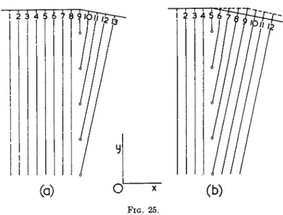
pictured in Fig. 8 can be repeated an indefinite number of times so that an indefinite number of closed dislocation lines can be obtained, each one enclosing the next younger one. The area of these closed dislocation lines can be increased by the process illustrated in Fig. 6, and they can be driven to- ward the outer border of the block (not indicated in Fig. 8), which will make them disappear from the picture. Every closed dislocation line produces a mean shift of the upper part of the block with respect to the lower part, always in the direction of the x-axis; any time a closed dislocation line is driven to the border, the corresponding mean shift has become equal to a.
In the picture developed here the whole slip takes place along a single glide plane. Although, as mentioned before, there are no experimental data concerning simple cubic lattices, it may be noted that in aluminum, which has a face-centered cubic lattice and where slip occurs along a (111) plane in the direction [10Ϊ], slipping along a single glide plane has been observed over distances of the order 1500 to 2500 A.20
c. Mechanism for the Production of Homogeneous Shear
An interesting extension of the case pictured in Fig. 7 is obtained when we suppose that there is also a screw dislocation in the field along a line passing through the point A perpendicular to the plane of the drawing and extending from the under surface of the block until the upper surface, with characteristic vector [0, 0, a]. In this case the movement of the sweep- ing dislocation (the segment parallel to the x,y-plsnie) will take place along a helicoidal surface, ascending one atomic distance upward (or de- scending downward, as the case may be) in each complete rotation.
The result obtained here can be generalized.21 The anchored part of the dislocation line need not be normal to the plane in which, or parallel to which, the rotation takes place. If the anchored part of the dislocation line stretches out on both sides of this plane, with characteristic vectors bi on one side and 1)2 on the other side, we shall have at the node bi = b2 + b, where b is the characteristic vector of the sweeping dislocation. Since the latter must satisfy the condition b · v = 0, where v is the unit normal to the plane of motion, it follows that
bi*v = b2*v
20 R. D. Heidenreich and W. Shockley, ref. 5, pp. 57-75, in particular p. 60; A. F.
Brown, Nature 163, 961-962 (1949); D. Kuhlmann-Wilsdorf and H. Wilsdorf, Ada Metallurgica 1, 394-413 (1953).
For comparison it may be mentioned that in the case of aluminum a = 4.05 A.;
length of the characteristic vector of a unit dislocation %a \/2 = 2.87 A.
21 The mathematical formulation of the process is given by B. A. Bilby [Phil. Mag.
[7] 44, 782-785 (1953)]. Bilby is rather concerned with a more general problem, to which we shall briefly return in Section II-5 (c).
without dislocations, over a distance equal to the characteristic vector of that dislocation. Hence in every turn of our sweeping dislocation, the dislocation suffers a displacement of magnitude bi or of magnitude b2 (or, rather — b2), depending on the direction of rotation. Of importance is only the step or pitch bi-v = b2v perpendicular to the plane of rotation. When this step is different from zero (which means that bi and b2 have a screw component in the direction of the normal v), the sweeping dislocation in each turn ascends (or descends) over a distance equal to this step. (The word
"ascend" is chosen, since "climb" has been adopted by Read for the nonconservative motion of a dislocation line. See Section 1-5(a) and refer- ence14.)
Since in each rotation the sweeping dislocation produces a shift of magni- tude b of the part of the lattice on one side of the plane of rotation with respect to the part on the other side, the result of this process is a homo- geneous shear of the part of the lattice traversed by the sweeping dislocation line, while ascending (or descending) along the anchored dislocation line.
This distinguishes the process from the original Frank-Read source, where the entire shear is concentrated along a single glide plane.
3. THE FACE-CENTERED CUBIC LATTICE
a. Unit Dislocations
Metals crystallizing in the close-packed face-centered cubic lattice are Cu, Pb, Ag, Au, AI, and Ni. Plastic slip occurs in octahedral planes, like (111), in the direction of a diagonal of a cube face, like [10Ϊ], etc.15
The unit cell of the lattice is usually pictured in the form of a cube with side a, and contains 4 atoms. Such a cell, with some of its atoms, has been represented in Fig. 9. The lattice can be described by various systems of basic vectors; the following system is symmetrical:
Ma, y2a, 0]; [^α, 0, Y2a\; [0, Y2a, Y2a]
This set determines a unit eel with volume J^a3, containing one atom. They are the shortest lattice vectors and thus correspond to closest atomic pack- ing. All other lattice vectors can be built up from this set.
The three perfect unit dislocations have these lattice vectors as charac- teristic vectors.
One could imagine a dislocation with vector [j^a, Ya, 0] to be obtained by making a partial cut according to a plane (110) and driving the two sides apart over the distance Υαλ/2. However, we arrive at a more satis-
164 J. M. BURGERS AND W. G. BURGERS
QPR: (MÖ
F I G . 9.
factory picture by starting from the octahedral plane QPR (111) with the atoms Q, F, P, E, Ä, D. These are represented again in Fig. 10, together with the corner atom B (above the plane of the drawing of Fig. 10) and an atom C still higher (in Fig. 9 BC = FB = Hay/2). The sides of the triangular meshes in Fig. 10 are Ηα\Ζ^>\ the distance between successive octahedral planes (measured perpendicularly to the plane of Fig. 10) is Hay/%' The atoms in successive layers are situated so that each atom fits into a triangular hollow between the three atoms below it. Since a layer of atoms can fill up only one-half of the available hollows, the next layer comes above the other half of the available positions, while the third layer comes just above the atoms of the first layer. When the positions Q, F, - - - D are labeled a, the positions of the atoms in the next layer β and those in the third layer 7, the regular sequence of the layers can be represented by the scheme · · · aßyaßyaßy
Now suppose that part of a ß layer is removed. We can bring together the layers immediately above and below it by approaching them over the dis- tance }ia\/S perpendicular to the (111) plane, that is, by moving the 7 atoms over the vector [Πά, Ύ/φ, Υφ\ Since this layer must come into the relation of a β layer to the a layer below it, it is necessary at the same time to introduce a shift parallel to the plane QPR (111) of amount Hay/§ in the direction RF, that is, over the vector [Hä, }£ä, H<A- The atoms which originally were in 7 positions are then brought into β positions. The total
FIG. 10.
resulting shift is determined by the sum vector [}^ä, }^äy 0], or with a change of sign by [^α, 3^α, 0], in the direction of CB or BF in Fig. 9. In this way we have obtained the desired perfect unit dislocation.
The part of the original β layer which has been removed can be bordered by an arbitrary dislocation line in the (111) plane. The direction QP [110]
would give a glide plane parallel to the cube face QPB (001); such a glide plane, however, is not observed. The directions QR [Oil] and PR [10Ϊ]
give as glide planes octahedral planes OQR (111) and OPR (ill) (not pictured in Fig. 9). To illustrate the second case, Figs. 11 and 12 have been constructed. In Fig. 11 the plane PRS has been taken as representative for (ill) and Fig. 12 pictures the situation of the atoms P, G, S, H, Ä, E in this plane and that of the atoms F, B, C above it. The glide direction is parallel to PS or FB [110].
Figure 13a gives a rough schematical section of the system of layers parallel to QPR (111) by a plane (101), which plane in Fig. 11 passes through the atoms Q, By S, E. This plane cuts QPR (111) according to the line QE [Ϊ2Ϊ], and PSR (111) according to ES [121]; it is perpendicular to both. Since we had assumed that the ß layer was bordered by a line parallel to PR, the dislocation line is perpendicular to the plane of the paper in Fig. 13.
I t must be observed that the transition from the γ situation to the ß situation in the layer above the partly removed ß layer is obtained by a gradual distortion, combined with a distortion in opposite sense of the a
166 J. M. BURGERS AND W. G. BURGERS
FIG. 12.
layer immediately below the ß layer. This distortion is accompanied by ten- sions in the lattice. Higher up above the y-ß layer, and similarly lower down below the a layer, the distortions distribute themselves over greater and greater distances and consequently become weaker and weaker, so that they soon become practically unobservable.
The migration of the dislocation can take place by movements of the
(normal)
SECTION BY PLANE (ΐθϊ) OR BY ( M ° )
FIG. 13.
atoms parallel to PS. The magnitude and the direction of an individual jump can be represented in Fig. 12 by a vector like BC of length ^a\/2.
The direction oi PS cannot be easily represented in Fig. 13, since it is neither parallel, nor perpendicular to the plane QSE (101); it would only be possible to indicate its projection ES on this plane, which makes an angle of about 109.5 deg. (2 tan" 1\ / 2 ) with the direction of QE [Ϊ2Ϊ].22
b. Frank's Sessile Imperfect Dislocation
In order to obtain a satisfactory fit of the atoms on both sides of the re- moved part of the ß layer, the shift of magnitude %ay/§ parallel to RF in the (111) plane is not necessary. Another good fit is obtained if we restrict to a relative displacement of the atoms in the adjacent a and y layers in a direction perpendicular to the (111) plane. I t is evident, however, that in
22 The unit dislocation [}^a, J£a, 0] can be decomposed into edge and screw com- ponents in various ways, depending on the dislocation line. With respect to a dis- location line parallel to PR [ΙθΓ] there will be an edge component [J^a, J^a, Υ±α\ and a screw component [^α, 0, \4fi\. With respect to a dislocation line parallel to QP [Ϊ10], it would be of the pure edge type. The same unit dislocation also could have a dis- location line perpendicular to the plane QPR (111); in that case there would be a screw component [J£a, J£a, }ia], combined with an edge component [%α> %α, \%α\.
This latter decomposition will be considered in a different sense—with dislocation line parallel to PR—in Section 11-3(6) and (c).
Figs. 13a-13c can also be considered as sections by a plane (110). Taking the dis- location line perpendicular to the plane of the drawing will now make this line to be parallel to [Ϊ10], that is, to QP. The dislocation vector [J^a, }£a, 0] would then be in the plane of the drawing, and the same applies to the vectors of the imperfect dislo- cations considered below in Sections 11-3(6) and (c).
168 J. M. BURGERS AND W . G. BURGERS
this case a γ layer will come to follow immediately upon an a layer. Thus the original stacking order is disturbed and we arrive at the order
• · · aßyayaßy · · · . This means that we have obtained an imperfect disloca- tion, since the stacking fault can be recognized over the whole region where the ß layer had been removed. A schematical representation is given in Fig.
136. In this case there are no horizontal distortions in the 7 layer above the partly removed ß layer, nor in the a layer below it.
This imperfect dislocation cannot migrate. Its characteristic vector is [}ία> λΑα<> }i<A™ Dirt there are no rows of contiguous atoms with this direction in the lattice, so that no migration can take place in this direction by simple jumps. A migration of the dislocation line in the plane (111) would require the removal or the introduction of atoms, which can only be the result of diffusion processes. The imperfect dislocation considered here is therefore called a sessile imperfect dislocation (also called a Frank partial dislocation).24 Its dislocation line must be situated in the (111) plane, that is, in a plane perpendicular to its characteristic vector.
c. Shockley's Glissile Imperfect Dislocation
A comparison of Figs. 13a and b shows that their difference is due to the fact that in a a 7 layer, through distortions parallel to the (111) plane, passes into a β layer, whereas this does not take place in b. The distortion from 7 positions immediately above an a layer to β positions is also possible without the accompanying removal of a part of a β layer; this has been indicated in Fig. 13c. Here it is supposed that in the layer marked 7-β, along a line through the point X, appropriate horizontal shifts of the atoms have been introduced, of amount %a\f§ parallel to RF (making an angle with the plane of the drawing of Fig. 13). The line through X in that case marks a discontinuity of the structure: on one side of it the atoms are in
23 In order to define the characteristic vector by means of a circuit in the way ex- plained in Section 1-5(6), we remember that in the case of a perfect dislocation as pictured in Fig. 13a we can use any closed circuit encircling the edge of the partially removed β layer. With an imperfect dislocation the circuit cannot be closed, since it may not pass through the region where the stacking order is disturbed. In the case of Fig. 13b we start from a point 1, considering it as belonging to the upper part of the lattice, go around the border of the partially removed β layer, and end at the point 2, considered as belonging to the lower part of the lattice. This circuit is
"mapped" onto a perfect lattice; if 2 is taken sufficiently close to 1, it will then show a closing fault, of amount [>£α, %α, }ia\.
In the case of Fig. 13c we likewise must start from a point 1, considered as belong- ing to the upper part of the lattice, and go around the point X, in order to arrive at 2, close to 1, but considered as belonging to the lower part of the lattice. When this circuit is mapped onto a perfect lattice, the closing fault will be [%α, %α, %ä].
24 F . C. F r a n k , Proc. Phys. Soc. (London) A62, 202-203 (1949); see N a b a r r o , ref. 4, p . 383; Cottrell, 4a, p . 75; R e a d , 4b, p p . 98-101.
SECTION BY PLANE (lOT)
F I G . 14.
7 positions with respect to the a layer just below; on the other side the atoms are in ß positions with respect to the a layer. Corresponding shifts of position will be necessary in the layers higher up; however, the shifts here take a more gradual character, distributing themselves over greater and greater distances, so that they become less and less perceptible. The tensions produced in this way have the consequence that also the a layer and the layers below it will be subjected to certain distortions—of grad- ually diminishing character—opposite to the distortions in the layers above.
I t is only in a single layer that there is an abrupt change of position.
The type of deformation obtained in this way is again an imperfect dislo- cation. Since it depends on shifts parallel to the (111) plane, the dislocation line can freely migrate over the (111) plane; consequently we now have arrived at a glissile imperfect dislocation (also called a Shockley partial dis- location) ,25 Its dislocation line must necessarily be situated in an octahedral plane containing the characteristic vector [%a, }/§a, }/&ä], that is, in the present case the plane (111).
A schematic picture of the situation of the atoms in a slightly different case is given in Fig. 14. The diagram again represents a section by the plane QSE (101) of Fig. 11, but it has been supposed that the transition from the normal stacking order (left-hand side) to a faulty order (right-hand side)
26 R. D. Heidenreich and W. Shockley, ref. 5, pp. 71-74; see Nabarro, 4, pp. 378- 382; Cottrell, 4a, pp. 72-75; Read, 4b, pp. 97-98.

![Figure 6a pictures a dislocation line with the same characteristic vector [a, 0, 0], bounded by a closed line in the glide plane (x,i/-plane), the seg-ments AB and DC being of screw type, AD and BC being of edge type](https://thumb-eu.123doks.com/thumbv2/9dokorg/1178693.86390/18.664.197.477.101.386/figure-pictures-dislocation-characteristic-vector-bounded-closed-glide.webp)