THE CARTESIAN DIVER
By H . H O L T E R
Carlsberg Laboratory, Copenhagen, Denmark
I . I n t r o d u c t i o n . . . . . . . . . . 9 3
I I . S t a n d a r d D i v e r (μ,Ι-Diver) . . . . . . . . 9 4
A . M a k i n g t h e D i v e r . . . . . . . . . 9 7
B . C a l i b r a t i o n o f t h e D i v e r . . . . 9 8 C. D e t e r m i n a t i o n of t h e S p e c i f i c G r a v i t y of t h e D i v e r G l a s s . . 9 9 D . D i m e n s i o n s a n d S h a p e s . . . . 1 0 0
E . F i l l i n g t h e D i v e r 1 0 1 F . D i v e r C h a r g e 1 0 5 G . P r e v e n t i o n of G a s L e a k a g e f r o m t h e D i v e r . . . . . 1 1 0
I I I . T h e o r y o f t h e D i v e r . . . 1 1 1 A . G e n e r a l R e m a r k s . . . . 1 1 1 B . D e n o t a t i o n s . . . . 1 1 3 C. D i v e r E q u a t i o n f o r t h e I d e a l C a s e . . . . 1 1 4 D . I m p e r f e c t i o n s o f t h e D i v e r S y s t e m . . . . 1 1 6 I V . M e a s u r e m e n t o f F a n d Ρ . . . . 1 2 4 A . D e t e r m i n a t i o n o f V, t h e D i v e r C o n s t a n t . . . . . 1 2 4 B . A d j u s t m e n t o f E q u i l i b r i u m P r e s s u r e . . . . 1 2 5 C. I n f l u e n c e o f C h a n g e s i n T e m p e r a t u r e . . . . 1 2 7 V . A p p l i c a t i o n s o f t h e S t a n d a r d D i v e r . . . . 1 2 7
R e f e r e n c e s . . . . . . . . . . . 1 2 8
I. INTRODUCTION
We owe the discovery of the usefulness of the Cartesian diver as a tool for microgasometric measurements to the acumen of Linderstrom-Lang.
Since his first description (Linderstrom-Lang, 1937), a great number of variations of the original diver have been developed, proving that the versatility of the diver principle permits its adaptation to a wide range of uses and orders of magnitude. In view of this versatility, it is incorrect to call the Cartesian diver a "respirometer". I t was never intended to be only that, and in fact, the very first application of the diver principle by Linderstrom-Lang and Glick (1938) concerned the determination of a non-respiratory enzyme.
Many of the advantages and difficulties involved in the use of the various forms of the Cartesian diver are, of course, common to all forms, since they are related to the Cartesian diver principle as such. I n the following, these common traits will be presented by means of a descrip
tion of the diver in its original, and still most widely used form, the ' ' standard diver '5.
93
94 H. HOLTER
II. STANDARD DIVER (/J-DIVER)
A Cartesian diver measures the buoyancy of an open, gas-containing vessel. I t consists of a container, surrounded on all sides by liquid, and enclosing a gas space which enables the diver to float. If the pressure on the liquid is changed, so is the volume of gas enclosed, and the diver rises
F I G . 1. D i a g r a m of C a r t e s i a n d i v e r a p p a r a t u s . D i v e r : a, b o t t o m d r o p ; 6, n e c k s e a l ; c, m o u t h s e a l ; d, g a s p h a s e . A p p a r a t u s : A, r u b b e r t u b i n g ; B, c o a r s e s c r e w ; O, fine s c r e w ; D, m a n o m e t e r ; E, flotation v e s s e l ; F, c i r c u l a r m a r k (in m o s t w o r k r e p l a c e d b y t h e c r o s s - t h r e a d of t h e r e a d i n g m i c r o s c o p e ) ; G, m a n i f o l d ; H, t h r e e - w a y t a p ; J, p r e s s u r e t u b i n g ; K, g r o u n d glass j o i n t (from H o l t e r , 1943).
or sinks. If, on the other hand, gas is absorbed or liberated in the diver, then a corresponding change occurs in the pressure necessary to bring the diver to rest at a given level ; this ' ' equilibrium pressure ' ' can be measured very accurately, and from it the change in the amount of gas can be calculated.
The essential parts of the apparatus are shown in Fig. 1. To the right is the diver, a small thin-walled tube with or without bulb, and with a
solid tail which serves to regulate the weight of the diver and to place its centre of gravity as low as possible. The reaction mixture is placed at the bottom; in addition, the charged diver contains one or several "neck- seals" which are held by surface tension (only one, the indispensable oil seal, is shown in the figure). The flotation medium extends into the neck ("mouth seal") and limits the gas phase by a meniscus which forms the boundary between 4 ' inside5 ' and '' outside ' '.
FIG. 2. D i v e r a p p a r a t u s a s s e m b l y . A, m a n o m e t e r ; B, p r e s s u r e r e g u l a t o r ; C, w a t e r b a t h ; JD, w a t e r inlet ; JE7, c i r c u l a t i o n p u m p ; F, w a t e r o u t l e t filter ; G, air b o t t l e , accessible b y t u b e H; J , c o o l e r ; K, h e a t e r ; L, t h e r m o r e g u l a t o r ; M, N, l i g h t s o u r c e ; 0 , m a n i f o l d , c a r r i e d b y f r a m e P; Q, flotation vessels, c a r r i e d b y R, S, T; 17, r e a d i n g m i c r o s c o p e ; V, electrical accessories (from t h e c a t a l o g u e of O. D i c h , C o p e n h a g e n , B r o n d b y S t r a n d , D e n m a r k ) .
After filling, the diver is submerged in the flotation medium,1 in which gases are sparingly soluble. I t is contained in the flotation vessel E, in a constant-temperature bath. The vessel is by means of the manifold G connected to the manometer D, and by means of the compressor screws
1 A s o l u t i o n o f 2 7 · 2 g N a N 03, 13 · 7 g N a C l a n d 0 · 2 g N a - t a u r o c h o l a t e i n 5 9 m l w a t e r ( d p '5 0 = 1 · 3 2 6 ) . C o n c e r n i n g t h e p r o p e r t i e s a n d s e l e c t i o n o f a s u i t a b l e m e d i u m , s e e H o l t e r ( 1 9 4 3 ) .
96 H . H O L T E R
B and C the pressure is so adjusted that the diver is made to float, and brought to a standstill at the mark F (which in practice is often replaced by the ocular cross-hair of the reading microscope). The corresponding difference of level in the manometer branches is then read off. The open branch of the manometer is connected to a large air bottle in the thermo
stat, which makes the diver independent of barometric pressure changes.
Figure 2 shows an example of the whole apparatus assembled.
The sensitivity of the diver depends on the volume of the gas phase.
When Brodie's solution is used in the manometer, 1 atmosphere corre
sponds to 10,000 mm of fluid. A pressure change of 1 mm, which is easily read on the manometer, corresponds to a volume change of 1 in 10,000.
For the "/zl-standard diver" in the volume range of 1-10 μΐ, this results in a sensitivity of 1-10 χ 10~4 μ\ of gas.
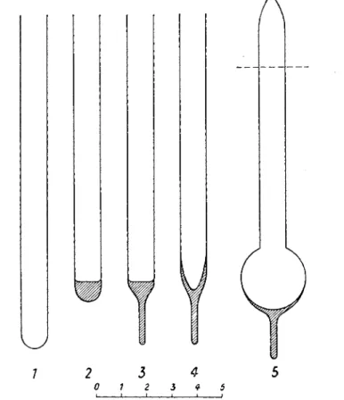
F I G . 3 . M a k i n g of d i v e r a c c o r d i n g t o Boell et al., ( 1 9 3 9 ) . S t a g e 1 - 3 : E n d of t u b i n g is collapsed a n d d r a w n o u t t o form a tail. S t a g e 4 : Glass is a c c u m u l a t e d a b o v e t h e tail.
S t a g e 5 : C a p i l l a r y is sealed a n d b u l b is f o r m e d b y h e a t i n g t h i c k - w a l l e d p a r t in a m i c r o flame. N e c k is c u t a t desired l e n g t h (from H o l t e r , 1 9 4 3 ) .
7
A. MAKING THE D I V E R
Most of the methods for making divers that have been described (Claff, 1948 ; Lazarow, 1950) adhere to the principle used by Boell et al., (1939), in which the pressure of the air volume enclosed in a sealed piece of capillary tubing is employed in blowing up the diver's bulb (Fig. 3). The method is well suited for making relatively thick-walled divers with a volume larger than 10 μ\, but it is rather wasteful with the calibrated capillaries. This method has been improved by Claff (1948) who has devised a jig for holding the divers during the glass blowing. The jig facilitates the production of well-shaped and uniform divers.
Another method of blowing divers has been described by Holter (1943). I t is more economical with regard to calibrated capillaries and is, according to our experience, superior for the production of divers smaller
d e F I G . 4 . M a k i n g of d i v e r a c c o r d i n g t o H o l t e r ( 1 9 4 3 ) . S t a g e a: Glass d r o p fused o n t o e n d of c a p i l l a r y . S t a g e b-c: C a p i l l a r y c o n n e c t e d t o m o u t h b y t h i n , l o n g (!) r u b b e r t u b i n g ; r o t a t i n g o v e r m i c r o flame a n d h e a t i n g o n l y glass d r o p , t h e air s p a c e is " b l o w n i n t o "
t h e d r o p . S t a g e d-e : Glass t h r e a d for t a i l is fused o n t o t h i c k - w a l l e d p a r t of b u l b , h e a t i n g t h r e a d s t r o n g l y a n d b u l b lightly. N e c k is c u t a t d e s i r e d l e n g t h (from H o l t e r , 1 9 4 3 ) .
4
98 H. HOLTER
than 10 μΐ. In this method, the blowing pressure is supplied by mouth through a piece of rubber tubing. The glass destined for the diver body is taken from waste glass which is fused to a drop, and sealed on to the end of the capillary. Heating only this drop, and under constant rotation, the hollow of the diver bulb is "blown i n t o " the solid glass drop. The tail is sealed on after the formation of the bulb (Fig. 4).
The difficulty involved in the making of smaller divers is chiefly due to the circumstance that the wall thickness of the glass tubing employed must be very small, since the ratio between diver surface and volume enclosed changes in disfavour of the latter with decreasing volume. The glass of the tubing must be chosen so thin that the buoyancy of the diver makes it possible, by means of ample glass in the tail, to place the centre of gravity so low that the diver floats in an upright position.1 The follow
ing values of tube diameter and corresponding wall thickness may serve as a guide to the selection of suitable capillaries :
I n s i d e d i a m e t e r o f t h e c a p i l l a r y
( w i d t h o f t h e d i v e r n e c k ) W a l l t h i c k n e s s
i n m m i n m m
0 - 6 5 - 0 - 7 5 0 - 0 8 - 0 - 0 9
0 - 7 5 - 0 - 8 5 0 - 0 9 - 0 - 1 0
0 - 8 5 - 1 - 0 0 - 1 0 - 0 - 1 2
> 1 0 0 - 1 2 - 0 - 1 5
B . CALIBRATION OF THE D I V E R
When a diver of approximately the desired size has been prepared by one of the methods mentioned, it has to be brought to the weight that corresponds to its size and the charge which it is intended to contain.
The charge normally consists of a certain volume of water, vw (bottom drop + neck seals), the oil seal, voib and the mouth seal, vM. The magnitude of the charge is decided upon, according to the purpose of the experiment.
The total volume, vT, of the diver is determined by weighing it empty and
1 U p s i d e - d o w n d i v e r s m a y , o f c o u r s e , b e e m p l o y e d . T h e i r c h i e f d r a w b a c k s a r e : (1) I f t h e y h a v e n o t a i l a t a l l , t h e i r c a l i b r a t i o n i s v e r y difficult ; if t h e y d o h a v e a t a i l t h e y u s u a l l y d o n o t float v e r t i c a l l y u p s i d e d o w n , b u t i n s o m e s l a n t i n g p o s i t i o n , w h i c h is t e c h n i c a l l y i n c o n v e n i e n t . (2) T h e r i n s i n g of t h e m o u t h s e a l i s v e r y a w k w a r d .
filled with water. The desired weight, gD, of the diver is then given by the formula (compare Section III) :
ντ φ M — ν oU φ oU — vw<j>w — vM ΦΜ
9D = 7
Φοί
where φΜ, φοφ φΐν, <f>gl are the densities of the flotation medium, the oil (paraffin oil) and the diver glass. All these values are determined once and for all ; the only one that may cause trouble is the density of the glass (see next section).
The diver is then brought to the weight gD (within 0 · 1-0 · 2 mg) by fusing on to the tail the required quantity of glass of the same specific gravity, most conveniently applied as an even thread of known weight per cm.
After cleaning and drying, the diver is given a test filling with the chosen charge. If properly calibrated, the equilibrium pressure should not deviate more than 20 cm from the barometric pressure. If necessary, smaller adjustments are made by correcting the length of the mouth seal (see Section II, F.3).
C. DETERMINATION OF THE SPECIFIC GRAVITY OF THE D I V E R GLASS
Since the specific gravity shows considerable variation not only for different glasses, but also within different lots of the same glass, it is impossible to rely on the commercially accepted figures.
The specific gravity is most conveniently determined by means of the Mohr-Westphal balance : a piece weighing 2-5 g is cut from the tubing in question, and a thin, hooked glass thread is fused on to it. By means of this hook the piece of glass is attached to the wire loop which otherwise carries the sinker of the Mohr-Westphal balance, and its weight is deter
mined in air and in water with an accuracy of 1 mg. The coefficient of expansion of the glass is so small, that the temperature at which the determination is made need only be considered in so far as the density of the water is concerned.
The specific gravity thus determined with an accuracy of 0 · 5% may be used directly in the calibration formula. Difficulties will only arise if insufficient care has been taken in the making of the diver tail and large air bubbles have been fused into the glass ; these bubbles naturally will change the buoyancy of the diver and may make it necessary to re-deter
mine its specific gravity. This is done most conveniently by the flotation method.
100 H . H O L T E R
As flotation liquids we use mixtures of ethylene bromide and bromo- form. The small table below shows the composition of the mixtures ; other commercial samples may possibly give somewhat different values.
E t h y l e n e b r o m i d e , m l
B r o m o f o r m ,
m l d | ?5°
2 0 5 2 - 3 1 4
1 5 10 2 - 4 6 0
1 5 15 2 - 5 2 9
10 2 0 2 - 6 4 3
Intermediate values may be found by interpolation—most easily if the mixing proportions are plotted on a logarithmic scale. The determina- tion of <j>gi with an accuracy of 0*5% requires, in general, testing with three to four flotation mixtures.
D . DIMENSIONS AND SHAPES
The dimensions of the divers most frequently used by us are approxi- mately as follows : Neck, inside diameter 0 · 9 mm, wall thickness 0 · 1
-M —
Ï Τ
F I G . 5. V a r i o u s t y p e s of d i v e r s a n d w a y s of c h a r g i n g t h e m . B, r e a c t i o n m i x t u r e (or o r g a n i s m ) ; A, a b s o r p t i o n s e a l ; O, oil s e a l ; M, m o u t h seal. ( 1 ) M a i n r e q u i r e m e n t s m a l l v o l u m e : cylindrical diver, a, g a s e x c h a n g e b e t w e e n Β a n d g a s p h a s e sufficient, also w h e n t h e surface of Β is small. 6, t h e g a s e x c h a n g e r e q u i r e s a l a r g e surface of Β (only possible in case of o r g a n i s m s w h i c h c a n r e s t o n a n a i r m e n i s c u s ) . (2) M a i n r e q u i r e m e n t l a r g e surface of B, air s u p p o r t n o t t o l e r a t e d b y o r g a n i s m : flask-shaped diver, c, r e l a t i v e l y l a r g e g a s s p a c e ; d, gas s p a c e a s s m a l l a s possible. T h e n e c k d i a m e t e r a n d t h e l e n g t h of M d e p e n d o n t h e i m p o r t a n c e of p r e v e n t i n g t h e g a s loss b y diffusion (from H o l t e r , 1 9 4 3 ) .
mm, length 9 m m ; bulb, diameter 2-3 mm; length of tail 5-8 m m ; total volume 10-12 μ\, weight 20-30 mg. These dimensions can readily be enlarged ; the only limitation is in the width of the neck which ought not to exceed 2 mm on account of the neck seals. For special problems, divers of volumes up to 200 μΐ have frequently been employed.
Matters are different if the diver is to be made smaller. A reduction of the neck diameter soon reaches its natural limit, as the increase in capillary forces makes the placing of the neck seals very difficult. I n our experience, this limit lies at about 0 · 6 mm. If accompanied by corre
sponding reduction of the length of the neck and abolition of the bulb, this neck diameter permits the construction of divers having a gas volume of about 1 μ\, which constitutes the practical lower limit in size of the standard diver.
Various shapes of divers have been employed. Some of these are shown in Fig. 5, together with a number of proposals for the variation in diver charge according to different experimental requirements.
E . FILLING THE D I V E R
The divers are filled by means of thin, capillary pipettes capable of measuring volumes of 0 · 2-2 μ! with an accuracy of about 1 %. They are operated by pressure from the mouth.
A special feature characteristic for work with divers, which must be considered when choosing pipette dimensions, is that strong capillary forces may occur as soon as a liquid bridge is formed between the pipette inserted into the diver and one side of the diver neck (see Fig. 9 (6)).
These capillary forces exert a side-pull on the pipette and may, when the pipette is elastic and yielding, pull originally well-centred pipettes out of position, thus contaminating large stretches of the diver wall.
Three different types of pipette have been used :
1. Type 1 (Fig. 6) is intended for the measuring of aqueous solutions of low viscosity (e.g. alkali used for C02-absorption in determinations of the respiration). The bore of the tip of these pipettes may be kept small, permitting of sufficient wall thickness to make the pipette rigid.
These pipettes are drawn from thick-walled thermometer capillaries having a bore of 0 · 2-0 · 3 mm. Before drawing the tip of the pipette, the thickness of its presumptive wall must be brought into proper relation to the bore. For this purpose, the capillary is heated and widened into a bubble close to one end. As soon as the bubble has reached the desired dimensions (as a guide : wall thickness equal to half the bubble's diameter), a very slight pull is applied and the capillary is given the shape shown in Fig. 6 (a). I t is then heated over the micro flame at the point indicated by
102 H . H O L T E R
an arrow and pulled out (Fig. 6 (δ)). The resulting pipette tip should have an inside diameter of about 0 · 07-0 · 12 mm, and an outside diameter of about 0· 15-0· 25 mm, all according to the size of the diver to be filled.
2. The second type of pipette resembles the first one. I t is intended for viscous liquids, chiefly paraffin oil, and the only difference from type 1 consists in the width of the bore, and the corresponding wall thickness of
Ψ
F I G . 6. M a k i n g of d i v e r p i p e t t e (from H o l t e r , 1 9 4 3 ) .
the tip. In order to avoid inconveniently high pressure of discharge, the opening must not have a diameter below 0· 15-0· 18 mm, and the glass thickness must therefore (since the outside diameter of the pipette must not exceed 0 · 25 mm, on account of the dimensions of the diver neck) be about 0-04 mm. Hence, when widening the capillary, the bubble (Fig.
6 (a)) is made so large that wall thickness and diameter are in the ratio of about 1:4, whereupon the tip of the pipette is drawn out to a thickness (outside diameter) of 0 · 2-0 · 25 mm.
3. The third type (Fig. 7) of pipette is the braking pipette (Holter, 1943 ; Claff, 1947). I t is used chiefly for the transfer of cells and pieces of tissue (which by their dimensions determine the opening of the pipette), together with known and small amounts of liquid.
Its principle consists in regulating the rate of intake and discharge not by the dimensions of the mouth of the pipette, but by slowing down the air current which simultaneously runs through the upper opening of the pipette.
Figure 7 shows the cheapest and most easily made type of braking pipette; its brake consists of an extremely narrow capillary channel forming the upper end of the pipette. The making of the pipette is directly apparent from Fig. 7. A is the pipette proper, a thin-walled cylindrical capillary of outside diameter 0 · 3-0 · 5 mm, drawn at its upper end into a
hair-thin tip E. By means of a cork, B, smoothly cut in halves length
wise and equipped with a longitudinal groove, the pipette is fixed in the glass tube ("jacket tube"), 0, which at its upper end carries the rubber tubing D for sucking and blowing. Instead of the cork arrangement, the pipette can also be fitted into a tapering jacket by means of some cement.
Β
A
F I G . 7. B r a k i n g p i p e t t e . A, p i p e t t e ; B, cleft c o r k ; (7, j a c k e t t u b e ; D, r u b b e r t u b i n g ; E, b r a k e (from H o l t e r , 1943).
The use of these various types of pipettes follows general microchemi- cal principles for handling 0 · 1 μΐ samples, and cannot be discussed here (for detailed description compare Holter, 1943). As shown in Table I I I (p. 125), the pipetting does not require great accuracy in volume. The mechanical delivery of pipette contents, however, has to be done rather carefully, in order to place the various drops and seals of the diver charge
104 H. HOLTER
exactly where they are needed. For this purpose, various accessory diver- filling devices have been described (Holter, 1943; Lazarow, 1950); the
latest, constructed by E. Boell, is shown in Fig. 8. I t is a very attractive apparatus of stainless steel, and requires less space than its predecessors.
F I G . 8. Boell's diver-filling a p p a r a t u s . A, ball a n d s o c k e t c l a m p s ; B, m i r r o r ; (7, d i v e r c l a m p ; D, E, m o v a b l e slides ; F, r u b b e r t u b e t o m o u t h ; G, o p a l glass ; H, lens ; / , r a c k a n d p i n i o n ; K, selector s w i t c h (from t h e c a t a l o g u e of O . D i c h , C o p e n h a g e n , B r 0 n d b y S t r a n d , D e n m a r k ) .
The common principle for all these diver-filling instruments is that they must allow the pipettes to be adjusted exactly parallel to the diver's neck, and that they must permit the divers to be held and moved in such a fashion that the tip of the pipette is introduced in the centre of the neck.
Only in that way can the seals be delivered without being drawn up by capillary forces. Any filling device that fulfils these requirements, is suitable. The necessary mechanical accuracy depends entirely on the diver dimensions: 100 μ\ divers with a neck diameter of 2 mm can be filled by hand.
F . D I V E R CHARGE
The diver charge which is placed by means of these devices consists normally (see Fig. 5) of the following components : the bottom drop, the neck seals, and the mouth seal. The neck and mouth seals will be con
sidered separately in their respective sections, while the bottom drop, which normally is the easiest to place, needs only a few remarks.
1. Bottom Drop
The calculations of Linderstrom-Lang (1943) have led to the rule that the thickness of the layer of the bottom drop must not exceed 0 · 5 mm, in order to ensure a sufficient rate of gas diffusion. This rough rule refers to gas exchanges like those expected in many biological processes (of the order of magnitude of 10~2 μ,Ι per hour). Naturally, the rule is most important for cylindrical divers, but also if spherical or conical diver bodies are used, the gas exchange depends on the actual spreading of the bottom drop. If necessary (and permissible), the spreading may be aided by suitable wetting agents, e.g. an addition of 0 - 1 % sodium taurocholate.
The bottom drop which frequently contains living organisms, will often be introduced by means of braking pipettes, the width of which is determined by the size of the object. The pipetting is facilitated, and organisms will be spared, when the tip of the pipette does not have to touch the dry diver bottom, but instead may be dipped into an already existing drop. For this purpose a small amount (about 0· 1 μ\) is intro
duced as a "forerunner". Frequently one has to provide a series of divers in this way with "forerunners" for quick and secure reception of sensitive experimental objects. In that case it is necessary to keep the divers in a moist chamber until the placing of the actual charge, in order to prevent evaporation of t h e ' 6 forerunners ". This is especially important when working with salt solutions.
The technically most difficult cases are usually those in which the biological object is so large or so delicate that it cannot be transferred by means of a pipette. In these cases the diver is filled completely with the solution intended for the bottom drop, the object is led into the diver's mouth and permitted to sink to the bottom by gravity. Afterwards the excess solution is removed, the neck is dried (this is often unnecessary if the diver is silicone-coated, see the next section) and the filling is com
pleted as usual. This technique has been especially useful in the study of tissue culture samples (Zamecnik, 1941 ; Danes, 1955).
106 H. HOLTER
2. Neck Seals
Among the most characteristic features of the charged diver are the neck seals, the number and function of which depends on the purpose of the experiment. One neck seal at least is indispensable, namely, the seal of paraffin oil which prevents the exchange of water between the diver and the flotation medium.
The neck seals are all placed according to the method shown in Fig.
9. The pipette is led centrally into the diver neck so that its tip is at the level where the lower meniscus of the neck seal is to be placed. By blowing
F I G . 9 . P l a c i n g of n e c k s e a l ; t h r e e successive s t a g e s (from H o l t e r , 1 9 4 3 ) .
into the pipette a drop is first formed at the tip (Fig. 9 (a)), which grows until touching the diver wall (Fig. 9 (6)), and ends up by forming a
" s e a l " (Fig. 9 (c)). The better the pipette is centred, the shorter is the critical stage b during which a lateral pull acts on the pipette that may cause a spreading of the drop. This may be avoided in stage b by shifting the diver stand so as to remove the tip of the pipette a fraction of a milli
metre from the moistened side of the diver neck. As soon as the seal is formed the danger of spreading is much smaller.
It frequently happens, especially in the case of wide necks, that in order to make the seal reach the wall on all sides, it becomes necessary to blow more liquid out of the pipette than the neck seal is to contain. If this has been the case, the diver is lowered a little in order to bring the tip of the pipette away from the meniscus into the interior of the drop, and the excess liquid is sucked back into the pipette.
Another critical stage may be experienced at the withdrawal of the pipette. This applies only in case of very narrow diver necks combined with coarse pipette tips, in which case the neck seal may be pulled up along with the pipette. To avoid this, one removes the pipette from the neck seal with a slight jerk. A silicone coat on the outside of the pipette is a great help in these cases.
The dimensions of the neck seals : the lowest possible length (from meniscus to meniscus) of a neck seal depends on the diameter of the diver neck, but should in general not be less than 0 · 5 mm, as it otherwise may happen that the neck seal disintegrates. The upper limit is generally fixed by diffusion considerations and the number of seals to be placed in the neck. The individual neck seals must be separated by at least 1 mm of dry unmoistened glass if their mixing is to be securely prevented. This requirement will frequently conflict with the wish to keep the diver volume as small as possible. In practice, the length of the neck seals will generally be in the neighbourhood of 0 · 8-1 mm, except that of the oil which should be about 0-5 mm (cf. LinderstromLang, 1943, p . 359).
The minimum distance of 1 mm between the individual seals in the diver may be increased according to wish, with one exception however : the distance between the oil seal and the mouth seal should be as small as possible. The reason for this is given in the theoretical considerations of Linderstrom-Lang (1943, p. 377 ff.).
All neck seals move when the pressure in the diver system is changed.
This fact is utilized in an important feature of diver technique, namely the mixing of solutions during an experiment. Any drop of fluid which adheres only to the side of the neck wall, without forming a seal, is station
ary and can be mixed with a neighbouring neck seal, if the latter is moved by a suitable pressure change. The application of this principle has been tried several times, also in our laboratory, and was first des
cribed by Anfinsen and Claff (1947). The practical difficulty consists in the prevention of unintentional mixing. Anfinsen and Claff accomplished this by coating the inside of the diver neck with paraffin. Shortly after
wards, Schwartz (1949) and Waterlow and Borrow (1949) described the application of silicone-coating for the same purpose. This has, in practice, turned out to work very satisfactorily. Thanks to this device, practically all experimental arrangements used in the Warburg technique can be
108 H. HOLTER
duplicated in Cartesian divers (Andresen et al., 1951 ; Borrow and Pen
ney, 1951; Holter and Pollock, 1952; Schwartz, 1949; Waterlow and Borrow, 1949). Borrow and Penney especially (1951) have examined the adaptability of the silicone-coated diver to a great variety of experi
mental situations.
A slightly different system of mixing solutions has been employed by Claff and Tahmisian (1948), using a silicone-coated diver with two bulbs.
This device involves an increase in diver volume (and corresponding decrease in sensitivity), and may be useful in special cases, when rela
tively large volumes of solutions have to be mixed.
The actual mixing of neck seal and side drop may require considerable over- or underpressures, up to 50 cm Brodie's solution. These pressures can be applied by blowing with the mouth or (Claff and Tahmisian, 1948) by means of a special rubber bulb and valve. I n both cases it is advisable to cut the manometer off from the manifold by a three-way stop-cock during the mixing, to avoid the after-effects of a large displacement of the manometer fluid.
3. The Mouth Seal
The mouth seal has two important functions : first, it is the main obstruction to losses of gas by diffusion ; and for this reason it must have a certain minimum length (compare Linderstrom-Lang and Holter, 1942), generally several millimetres. Secondly, the adjustment of its dimensions in filling the diver regulates the initial equilibrium pressure to the desired value. The relation between the equilibrium pressure and the length of the seal depends on the size of the gas volume enclosed in the diver, but as a rough rule it may be assumed that in a 10 μ\ diver, a lengthening of the mouth seal by 0 · 1 mm changes the equilibrium pressure by 6-8 cm.
As generally it is desired to strike the equilibrium pressure with a pre
cision of a few cm, it follows that the length of the mouth seal should be adjusted with an accuracy of 0 · 1 mm.
Since for practical reasons the initial equilibrium pressure desired is nearly always the same (a few cm below 1 atmosphere), the length of the mouth seal is as a rule constant for a certain diver and a certain charge.
In filling, this length is determined by measuring the distance between the mouth seal meniscus and the diver mouth by means of a horizontal microscope, equipped with a micrometer screw.
Accordingly, the mouth seal is placed as follows: a pipette clamp holds a braking pipette ("air pipette") with a very finely drawn tip (inside diameter about 100 μ, outside diameter 150 μ), and a braking-tip.
After having placed the paraffin oil neck seal, the clamp stand with the diver is moved to the air pipette and centred. The tip of the pipette is led
into the diver neck to a depth of about 1 mm below the intended position of the lower meniscus of the mouth seal. The microscope is adjusted until the horizontal one of the crossed threads coincides with the diver mouth, and is then moved downward by means of the micrometer screw the desired length of the mouth seal. Using a fine hand pipette, a seal of flotation medium is now placed in the mouth of the diver (around the tip of the braking pipette which remains inserted in the mouth), and then lowered by suction of air through the braking pipette until the apex of the meniscus comes to rest (!) at the level of the horizontal thread. Figure 10
1 1
m
0 1 2 3mm ι Ι I ι
F I G . 1 0 . P l a c i n g of m o u t h seal (from H o l t e r , 1 9 4 3 ) .
shows the field of vision of the microscope at this moment (the vertical thread of the cross is omitted in the picture). Finally, the diver stand is quickly lowered to remove the air pipette from the diver neck, and the mouth seal is filled up to the rim of the diver mouth.
The mouth seal consists of the medium in which the diver is to float.
Since this medium is an almost saturated salt solution, it may precipitate crystals in the mouth seal during the various manipulations ; such crys
tallization must be avoided. For that reason we use medium diluted 1:1 with water for the placing of the mouth seal. A more diluted medium would be more convenient, but cannot be kept sterile for any consider
able length of time. Taurocholate (0 · 1-0 · 2%) is indispensable to prevent deformation of the menisci.
As long as the solution of the mouth seal is less concentrated than the diver medium, there is no difficulty when introducing the diver into the flotation vessel. The difference in density of the two solutions causes a rapid substitution of the mouth seal. This automatic exchange is entirely sufficient in the case of short mouth seals (about 1-1 · 5 mm) and wide
110 H. HOLTER
diver necks (diameter about 1 mm), in other words, in experiments where one usually expects rapid and large changes of the gas volume. If, in experiments with small effects, the initial equilibrium pressure must be established quickly and accurately, it is necessary to rinse the diver mouth after immersion with medium by means of a glass tube with capillary tip. The dry glass tube, equipped with rubber tubing for blow
ing, is lowered into the flotation vessel, and about 0 · 5 ml of the flotation medium is sucked into the tube ; the tip is then inserted in the mouth seal and the rinsing is done by gently blowing out most of the medium contained in the tube.
G . PREVENTION OF GAS LEAKAGE FROM THE D I V E R
The leakage of gases into the flotation medium is one of the main problems of the diver technique. No liquid seal has been found which could prevent the leakage completely. Rocher (1943) has reported the successful use of a mercury neck seal, but our own results with mercury seals have been very discouraging owing to the capriciousness of the surface tension of mercury droplets.
However, leakage can be reduced to tolerable rates in various ways.
For oxygen and nitrogen, the gas solubility in the flotation medium is so low that no further precautions need to be taken, and the problem thus arises only if carbon dioxide is one of the components of the diver gas phase. In these cases, two devices have stood the test of practical use : the introduction of a glass stopper in the mouth seal (Linderstrom-Lang and Holter, 1942), and the use of a saturated solution of benzoic acid in mineral oil ("MOBA") as an oil seal (Borrow and Penney, 1951).
The glass stopper in the mouth seal (Fig. 11) must be tight enough to substantially reduce the diffusion area ; and it must be loose enough to allow the stopper to rest freely on the mouth seal meniscus and not to hamper the free movement of the meniscus during measurements. A diameter about 30-40 μ smaller than the inside diameter of the diver's neck meets both requirements. A solid glass stopper is very easy to make, but is too heavy. Hollow glass stoppers of correct specific gravity do not increase the diver's weight appreciably, but they are unpleasant to make. Unfortunately, we have not found a suitable plastic substitute for glass (Andresen et al., 1951), since the plastics so far tried have proved to be too permeable to C 02 ; an extensive search into the variety of materials now available might well be worth while.
The "MOBA" seal has been suggested and studied by Borrow and Penney (1951). I t reduces the C 02 leakage to about one-fifth of the
ordinary oil seal and seems thus to be sufficient for most purposes, including the determination of RQ.
Arrangements for maintaining a constant C02-tension in divers have been worked out by Danes and Kieler (1958).
ω
F I G. 1 1 . D i v e r w i t h glass s t o p p e r i n m o u t h seal (from L i n d e r s t r o m - L a n g , 1943).
III. THEORY OF THE DIVER
A. GENERAL REMARKS
At the actual moment of measurement, the diver will float at the level of the equilibrium mark and will be at equilibrium pressure. After the reading is taken, the diver is allowed to sink to the bottom of the flotation vessel where it remains between measurements, either at a constant
112 H. HOLTER
pressure (close to atmospheric pressure), or at a pressure which is slightly higher than the equilibrium pressure, and is varied after successive measurements parallel with this. The latter procedure reduces the errors due to excessive displacement of the neck seals and is therefore generally employed.
The equilibrium pressure (P) of the diver is the sum of several pres
sures : the pressure resting upon the ' ' free '' manometer branch, the hydro
static pressure difference read on the manometer (p), the hydrostatic pressure of the medium above the equilibrium mark, and finally the pressure originating in the capillary forces in the diver's neck. The con
dition that the change in equilibrium pressure is equal to that of the manometer reading is, therefore, that all pressures other than ρ are constant.
The basic principle of the whole method is given by the equation (Linderstrom-Lang and Glick, 1937):
gD + Voil<t>oil + Vw<l>w = ι /JV
V + voil + vw + gD^gl ψ Μ }
which expresses the condition that at equilibrium the "compound den
sity " of the diver is equal to that of the flotation medium (for denotations see p. 113). From this equation the total gas volume V of the diver at equilibrium pressure can be calculated. I t is a constant for each diver with a given charge of aqueous solutions (bottom drop + aqueous neck seals) and oil.
I t will appear from this sketchy summary of the principle of the measurement, to which type of gasometric instruments the diver belongs.
If kept continuously at equilibrium pressure, it is essentially a " constant- volume instrument". If, however, the diver rests at constant pressure most of the time, interrupted only by the short (1-2 min) readings at equilibrium pressure, the diver system will become more like a "con
stant-pressure instrument". The deciding factor here is the rate of adjustment of the equilibrium between liquid and gas phase inside the diver. If true equilibrium in this sense is attained during the short meas
urement of equilibrium pressure, the diver is a " constant-volume instru
ment". If not at all, it is a "constant-pressure instrument", and the determination of the equilibrium pressure is just a way of estimating the volume change at constant pressure. Since the difference between the formulas obtained even in the two extreme cases is slight (see Linder- strom-Lang, 1943), we shall regard the diver as a constant-volume instru
ment because the theoretical treatment is simpler. For detailed treatment see Linderstrom-Lang (1943).
The practical determination of V and Ρ with their experimental errors will be dealt with in Section IV. Here we shall consider the connec
tion between the change in amount of any given gas inside the diver, and the corresponding change in equilibrium pressure—all experimental errors excluded. We shall start with a theoretical treatment of one ideal case and in a following section we shall investigate how far the formulas derived are applicable to real cases.
Ideal case (the best approximation is the diver in Fig. 11, where diffusion is blocked by a glass stopper which is either attached to the diver or is loose and has the density φΜ (see Section IV, A)) : the rates of passage of all gases through the oil are infinite except those of water vapour and one other gas, X, which are zero. There is no passage of gases through the medium seal. The quantities of gas taken up by the medium can be disregarded. The oil is in constant equilibrium with the gas phase, except in the case of water vapour and the gas, X. The reaction mixture is in constant equilibrium with the gas phase.
In this case the diver is assumed to contain two gas spaces only, one with volume ω and one with volume V — ω (main gas space), separated by the oil seal. In respiration measurements, it is necessary to introduce a NaOH-seal into the diver neck and the gas space will, therefore, be divided in three. Since, however, in this case C 02 is quantitatively ab
sorbed by the sodium hydroxide, the conditions are much simplified so that this case needs no general consideration.
I t should be emphasized here that in the normal application of the diver as a biological tool, C 02 is the only gas which gives rise to compli
cations because of its high solubility in water, medium and oil. Wherever C 02 is absent the simple equation (8) (see below) is valid with consider
able accuracy, irrespective of the sizes of the oil and medium seals and the degree of equilibration of gases between V — ω and ω.
Β . DENOTATIONS
f temperature of the diver system (°C).
Β barometric height (cm Brodie solution).
ρ manometer reading (cm Brodie).
hM height of column of medium above the equilibrium position of diver (distance from surface of medium to meniscus of medium in the diver's neck at equilibrium).
P0 normal pressure (cm Brodie).
σ height of rise of the medium in the diver's neck due to capillary forces.
114 H. HOLTER
P equilibrium pressure (cm Brodie) = J5f + hM φΜ% +p + σφΜ. V total gas volume (upper + lower bubble) at equilibrium pressure
and f (diver constant).
ω gas volume of upper bubble (equilibrium pressure, f) (Fig. 11, p. 1 1 1 ) .
vT total volume of empty diver.
vM volume of medium in the mouth of the diver.
vw volume of reaction mixture in the diver.
vo U volume of oil in the diver.
φΜ, ΦΜ, φοίι, φρι densities of medium, reaction mixture, oil and glass, respectively.
gD weight of empty diver (mg).
7γ water vapour tension at f (index w : vapour tension of medium) (cm Brodie).
Pi partial pressure of gas i (index V — ω: lower gas bubble ; index w: upper gas bubble) (cm Brodie).
Vi total quantity of any gas i dissolved and undissolved in reaction chamber (μ\ at 760 mm Hg (P0) and f ).
(ν0){ same quantity reduced to 0°.
oc'i gas absorption coefficient : volume of gas dissolved per volume of aqueous phase (760 mm Hg and t°).
βΐ the corresponding quantity for the oil phase.
Di diffusion constant (cm2/hr).
pi (standard rate of passage) : gas volume in μ\ (at 760 mm Hg and f) which in 1 hr diffuses through a column with area 1 m m2 and length 1 mm, the difference between the partial pres
sures of the gas on both sides of the column being P0 ( 1 atmosphere). p{ = Di. . 100.
C . D I V E R EQUATION FOR THE IDEAL CASE
If there are η different gases in the diver, including the gas X but not including water vapour, we have the fundamental n—l equations :
(Pùv-ω = (Pi)œ = Pi (2) p .
and Vi = ^{V + Voaft + VvGc'i} (3)
f O r P g = p r e s s u r e i n a i r b o t t l e .
% I f t h e d i v e r c o n t a i n s a l o o s e s t o p p e r w i t h a d e n s i t y w h i c h is d i f f e r e n t f r o m ΦΜ, a t e r m s h o u l d b e a d d e d , v i z . Gsp/aj), w h e r e Gsp i s t h e r e d u c e d w e i g h t of t h e s t o p p e r a n d ap t h e n e c k a r e a o f t h e d i v e r (see S e c t i o n I V , A ) .
valid for all η gases except X, and
Σ Pi = Ρ + Ροίι-π«,-(Ρχ)ν-ω = Ρ-*Μ~(Ρχ)ω W
n-1
where Po i l is the negligible and constant hydrostatic pressure of the oil seal. From equation (4) we obtain :
{Ρχ)ν-ω~{Ρχ)ω = KM — TTw+Poil (5)
These equations immediately demonstrate the necessity of introducing the gas X as a means to establish equilibrium. I n its absence all the
(Pi) ν-ω could not be equal to (Ρ{)ω, and since
ΡοίΙ + π
Μ <
^wyΣ
(Pi)ω >Σ
(Ρΐ)ν-ωso that V — ω would grow at the expense of ω due to diffusion of some of the gases i. The quantity of X is assumed to be constant (nitrogen may be taken as an example) and, since the diver is supposed to be kept constant at the equilibrium pressure, (Ρχ)ν__ω and ( P ^ are constant too, and
Δ Σ Pi = ΔΡ (6)
n-1
expressing that the sum of the variations of the partial pressures of the gases evolved, or consumed in the diver, is equal to the variation of P . From equation (3) and equation (6) we obtain:
y *h . „ el
(7)^ V + Vrtfi +
Vuoi
P0 v 1which is the general equation for the calculation of changes in amounts of gas from changes in equilibrium pressure. Equation (7) is identical with that given by Boell, Needham and Rogers (Boell et ah, 1939, p. 331) :
((»«))* = Practical examples are :
1. The solubility of all gases is small ( a i and $ ~ 0 ; i = 02 or N2). This case comprises all experiments in air, N2 or 02, where C 02 does not occur, or in which all the C 02 formed disappears, e.g. through absorption by alkali (respiration experiments). Equation (7) here assumes the simple form :
Σ
YAP1 1 6 H. HOLTER
2. One of the gases ( C 02) is easily soluble in oil and reaction mixture.
Its partial pressure is small ( < 5 % ) in comparison with P . The other gas (e.g. nitrogen) is sparingly soluble and does not change in quantity. This case includes experiments in which acid is formed or disappears in a carbonate buffer system.
The equation for this system is
Δν
00ι= ψ [ ΐ
+ ν^ ψ ^ ) (9)
3. Diver equations for the case that the oil seal is impermeable to Borrow and Penney have suggested the use of mineral oil saturated with benzoic acid ("MOBA"), instead of paraffin oil as a protection against C 02 loss. Adopting this principle, and assuming complete block
ing of C 02 escape through the "MOBA" seal, leads to the equation:
<->
(see L i n d e r s t r 0 m - L a n g , 1 9 4 3 ) .
In all the examples given above, the temperature correction has been neglected. If experiments done at different temperatures are to be com-
(
— — — - 5 I has to be 2 7 3 \2il ô -f-1 J applied.
D . IMPERFECTIONS OF THE D I V E R SYSTEM
1. Diffusion and Attainment of Equilibrium
The first problem met with when going into the theory of the diver, is that of the attainment of equilibrium between the fluid reaction mixture and the gas space. As distinct from the existing macro respirometers, which are all equipped with some stirring device, the diver, and in fact all micro respirometers, are tacitly assumed to be able to function without stirring; diffusion being considered fast enough to secure equilibrium in systems of the dimensions here chosen.
Since the composition of the gas space practically always changes during an'experiment, it has been attempted to derive approximate formulas for non-stationary or quasi-stationary states (see Linderstrom- Lang, 1 9 4 3 ) . These formulas have been applied to the three cases depic
ted in Fig. 1 2 .
The divers are assumed to be filled with air initially. The gas volume, v, is kept constant and equal to 8 · 9 μ!1, and it is assumed that the meniscus A is impermeable to gases. The ratio between the volumes of liquid (vw) and gas phase (v) is constant and equal to .1/8· 9, but the shape of the fluid body is varied as indicated. The diffusion was investigated on the basis of two different assumptions :
(a) In each volume element Avw of the liquid phase, which consists of a dilute aqueous solution, C 02 is formed at the constant rate q.Avw μί per
ι II in
F I G . 1 2 . T h r e e diffusion s i t u a t i o n s (from Linderstr0m-Lang, 1 9 4 3 ) .
hour (at 760 mm Hg and f, the temperature of the diver). Example:
Carboxylase action of homogeneously suspended or dissolved material.
(b) C 02 is formed in an infinitely small element of the liquid phase (dilute aqueous solution). In case I this element is a half-sphere situated around the centre of the larger half-sphere, in cases I I and I I I it is a sheet at the bottom of the liquid cylinder. The rate of formation of C 02 is the same as under assumption (a), viz. q. Avw μ\ per hour. Example : Carboxy
lase action of material situated in living organisms. Excess of substrate so that the C 02 production is not influenced by the diffusion of the substrate.
1 T h e c h o i c e o f t h i s p e c u l i a r v a l u e i s e x p l a i n e d b y L i n d e r s t r o m - L a n g ( 1 9 4 3 ) .
118 H . H O L T E R
The result of the investigations of these six cases (Ia-IIIb) is seen in Fig. 13. F is given by
F (10)
and represents the ratio between the experimental and theoretical values of the rate of C 02 evolution. (Temperature 22-5°C, <x'C02 = 0-89,
1.0
0.8
t o .
0.4
0.2
L t
I II1 0 0 10 0 10 2 0
Time, min. — * ~
F I G . 1 3 . C 02 e v o l u t i o n i n v a r i o u s d i v e r c h a r g e s (from L i n d e r s t r o m - L a n g , 1 9 4 3 ) .
DCQ2 = 0· 067 cm2/hr, see Table I.) The abscissae are the times from the start of the experiment, i.e. when C 02 begins to form in aC02-free system.
Since the first stages of the reactions studied will usually have passed
T A B L E I
V A L U E S O F OÎÇ0Z, pC O a A N D DCQZ F O R D I F F E R E N T M E D I A A T 2 2 - 5 ° C
M e d i u m ac o2 Pco2 ^ c o2
c m2/ h r c m2/ h r c m2/ h r
W a t e r 0 - 8 9 5 - 9 0 - 0 6 7
N a N 03- N a C l m e d i u m 0 - 1 7 0 - 5 9 0 - 0 3 4
P a r a f f i n o i l 0 - 9 1 1 - 4 7 0 - 0 1 6
during the processes of filling and inserting the diver, and in the course of the time required for temperature adjustment, we see that the rate of measurement is unaffected by diffusion difficulties in the system here
considered. Figure 13 shows that even in the most unfavourable case I I I , we find the correct slope after less than 20 min so that no dangers can arise from this source of error unless the height of the bottom drop (b) is chosen considerably greater.
This is, of course, only strictly valid if q is independent of time, so that we can pick and choose the time interval in which q is measured. If the rate of C 02 evolution is variable and its entire curve is wanted, we shall have to reduce b sufficiently to make the study of the early stages of the process possible. This problem has been discussed by Linderstrom-Lang (1943). I t is not of great importance in most cases.
The above examples have dealt with evolution of C 02. In the case of gas absorption quite similar calculations can be made. There is, however, one additional fact which must be taken into consideration here, viz.
that there is an upper limit for q, which must not be exceeded if the con
centration of gas in any volume element of the liquid phase shall remain positive throughout a given experimental period. If we seek the condition for the gas concentration in any volume element to remain above a certain critical value, say that corresponding to a gas pressure of Pcrit, the formulas given by Linderstrom-Lang (1943) permit the calculation of the rate of absorption (q) corresponding to this minimum gas concen
tration. Table I I shows the value of PQ—Pcritf for different values of q;
T A B L E I I
V A L U E S o rPQ— Pc r i t ( A T M O S P H E R E S ) E> = 0 · 0 6 6 7 e m2/ h r ; a^0 a = 0 · 8 9 ; αθ 2 = 0 · 0 3 0
C a s e I I C a s e I I I
q (μΐ/hr) C 02 C 09 o2 c o2 o2 c o2 o2
0 - 0 0 5 0 - 0 0 2 5 0 - 0 0 3 3 0 - 0 1 0 - 0 0 5 0 0 - 0 0 6 6 0 - 0 2 0 - 0 1 0 1 0 - 0 1 3 1 0 - 0 4 0 - 0 2 0 2 0 - 0 2 6 2 0 - 0 6 0 - 0 3 0 3 0 0 3 9 3
0 - 0 0 2 6 0 - 0 0 4 0 0 - 0 0 2 9 0 - 0 0 5 1 0 - 0 0 8 0 0 - 0 0 5 7 0 - 0 1 0 2 0 - 0 1 6 0 0 - 0 1 1 5 0 0 2 0 4 0 0 3 2 0 0 0 2 3 0 0 - 0 3 0 5 0 - 0 4 8 0 0 - 0 3 4 5
0 - 0 1 5 0 0 - 0 0 3 3 0 - 0 2 7 4 0 - 0 2 9 9 0 - 0 0 6 5 0 - 0 5 4 8 0 - 0 5 9 8 0 - 0 1 3 0 0 - 1 0 9 6 0 - 1 1 9 6 0 - 0 2 6 0 0 - 2 1 9 2 0 - 1 7 9 4 0 - 0 3 9 0 0 - 3 2 8 8
the experimental period is assumed to be 5 hr. I t appears from this table that the values of P0—PcHt are much higher for oxygen than for carbon dioxide, owing to the smaller solubility of the former gas. In case III6, the oxygen pressure at the bottom of the liquid reaches the value
120 H . H O L T E R
zero after 5 hr if q = 0·04 μΐ/hr and the diver is filled with air initially ( P0= 0 - 2 1 ) .
2. Escape of Gas from the Diver (or Uptake of Gas by the Diver) The escape of any gas i from the diver through the medium seal is described by the equation (see Linderstrom-Lang, 1942) :
in which (Ρ^Ω ~ (P{)M> ^n e difference in atmospheres, between the partial pressures of the gas i in ω and over the medium in the diver vessel (Pig. 11 ), is assumed to be constant or to vary very slowly. (Ρ^)ω — {Pi)M may be positive or negative. The quantity of escaping gas is v{ in μ\ at 760 mm Hg and f. The time, t, is expressed in hours, A" and L"D are the area and length of the medium seal and are expressed in square millimetres and millimetres, respectively, and p" is the standard rate of passage through the medium. LD is calculated in all cases by dividing the volumes of the seals by the neck area. Concerning the error involved in this calculation see Linderstrom-Lang (1943) and Linderstrom-Lang and Holter (1942).
For numerical values of α', ρ and D for C 02 in different media, see Table I.
Since under similar conditions we have for the quantity of the gas passing the oil seal :
, l 2 )
where A', p\ and L'D are the corresponding quantities for paraffin oil, we arrive at the equation :
_/dvX _(dvi\ (Pi)v-(Pj)M ^1 3j
\dt)M \dt)oU UD L"B A pi A pi (stationary state).
An equation like (13) may be used for the calculation of the loss of gas from a diver in which ν — Υ — ω is large in comparison with w, vM and voil, and in which (Pi)v is nearly constant. We must, however, always reckon with an initial non-stationary period which depends upon L'D, L"D, voib ω, etc. ; but since, anyhow, the initial stages of the reactions taking place inside the diver are lost in the processes of filling the diver and temperature adjustment, equation (13) may be useful in some cases (see Linderstr0m-Lang, 1943), especially where the diver contains C 02 initially in finite quantities. The correction for the escape of C 02 by
means of control divers will in this case always require some minor calcu
lations, because the dimensions and charges of two different divers are never quite equal.
If (Pi)v changes continuously (the gas i being evolved or absorbed in the diver), the application of equation ( 13) is more uncertain and we must refer to the calculations in Linderstr0m-Lang's paper (1943). Figures 14 and 15 show the distribution of C 02 in a narrow-necked diver in such a case. The diver and its charge is as follows :
Total gas volume V = ν + ω = & μ\: ω = 1 · 6 μ,Ι ; voil = 0-2 μλ;νΜ = 1 · 6 μ,Ι, neck area 0 · 4 m m2 ; length of oil seal 0 · 5 mm ; length of mouth seal 4 mm (no glass stopper). Carbon dioxide is evolved at a constant rate q /xl/hr in ν (which contains a negligible quantity of reaction mixture).
The ordinates in Fig. 14 are the rates of the quantities of C 02 in the different parts of the diver, divided by q. t, the total quantity of C 02 at the time t. The factor φ in Fig. 15 is given by
and represents the ratio between the experimental and theoretical values of the ratio of C 02 evolution.
Since, however, the use of calculations of this type is too laborious for ordinary experimental work, the investigator will have to make use of one of the devices proposed to hinder the passage of C 02 so much that correction is superfluous. I t should be emphasized that generally it is the medium seal, situated in the mouth of the diver, which determines the rate of exchange of gases between diver and medium. The necessity of introducing mouth seals of suitable lengths should therefore be stressed (see Linderstr0m-Lang, 1943), and application of glass stoppers in the mouth seals recommended. In certain cases, however, the use of ' ' MOB A' ' seals may be advantageous. For most other gases than C 02 ( 02, N2) the loss or uptake through the mouth seal is very small (Linderstr0m-Lang,.
1943), unless the pressure gradient is high, as in the case erf divers filled with pure oxygen and immersed in a flotation medium saturated with air ; and even then the error is not substantial, p0% in NaN03-NaCl medium being of the order of magnitude of 0-01 (see Linderstr0m-Lang and Holter, 1942). The loss of oxygen from a diver with a neck area of 0-4 m m2 and a 4-mm mouth seal without glass stopper is thus 0 · 0008 /xl/hr.
If this loss is essential in comparison with the changes in gas volume measured, corrections may be introduced by means of control divers, or the medium may be saturated with oxygen, or a glass stopper may be used.
(14)
122 H . H O L T E R
l.Or- 1 1 1 ! ! 1
\ ~ C 02 in total gas
\ space ν+ω 0.9 V
t
o.8 ^ ^ ^ ^ ^-σ C 02 in main gas
-22 space ν υ
X3 c (Λ
I 0.71 1 1 1 1 1 1 1
I 0.2 I , « ! « 1 1 1 Ô
C 02 in ω
/ Total loss lo oil / —- and medium / _ Loss through / ^ ^ — " —" "~ medium seal (PM) y ^ Z - ^ » ——' * C 02 diss, in oil
£^~~~— ' seal (yoil)
0 2 4 6 8 10 Time, hours —>-
F I G. 14. C 02 d i s t r i b u t i o n (from Linderstr0m-Lang, 1943). «
1.1
φ 0.9 0.8
0 j I 1 1 1 1
0 2 4 6 8 10 Time, hours —>·
F I G. 15. L o s s of C Oa (from Linderstr0m-Lang, 1943).