M A S S S P E C T R O M E T E R F O R T H E I N V E S T I G A T I O N O F L O W C O N C E N T R A T I O N S O F F R E E
R A D I C A L S I N G A S E S
P . G . B E N T L E Y , J. B I S H O P and J. L E E C E
United Kingdom Atomic Energy Authority {Development and Engineering Group), Research and Development Branch, Capenhurst, Chester, England
This mass spectrometer has been built specifically for the investigation of free radicals in gases at high pressures. It is to be used at A.E.R.E., Harwell, for studying the reaction between graphite and carbon dioxide in reactor systems, and a possible application would be the examination of free radi- cals in flames [2]. Tests on the instrument performance have been confined to the measurement of traces of stable chemical impurities in gases, and the instrument is described chiefly in this light. Although the mass spectro- meter may be set up rather differently for free radicals and for ordinary chemical analysis, there is no difference in principle except in one respect:
for free-radical work, the inlet system to the spectrometer must be designed so that no wall collisions occur. This means that molecular beam techniques have to be used to transfer the sample from a reaction chamber into the spectrometer.
In designing the instrument, particular attention has been given to increasing the sensitivity for trace detection. The factors determining overall sensitivity are three. First is the maximum rate at which sample can be fed into the spectrometer; this is normally set by some deterioration of spectrometer characteristics at high flow rates but in this instrument it is limited by the behaviour of the molecular beam inlet system. The second factor is the efficiency of ionization in the spectrometer ion source, and the third is the sensitivity for ion detection. W e consider this sensitivity for ion detection in more detail, below p. 256.
C O N S T R U C T I O N
Fig. 1 shows the general layout of the instrument. The spectrometer itself is a single-focusing, 90° magnetic sector type with a radius of 6 in. For convenience in operation the collector slit is wide and the resolution only about 100; this, however, is quite adequate for the work to be done.
The molecular beam, electron beam and resulting ion beam are all
chosen for the molecular beam so that it fires through the ion source and straight into a cold trap. Sample gas is therefore pumped away very effi- ciently and prevented from reaching the ionization region after making a wall collision.
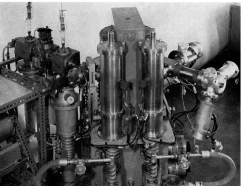
Particular attention has been given to the layout of the spectrometer tube so that the ends are readily accessible for fitting alternative inlet systems or collector systems if necessary. This is achieved by the basically triangular design shown in Fig. 2; the tube is supported at two points only by the pumping tubes to the two liquid-nitrogen cold traps. The cold traps are bolted to a low-level platform which also supports the magnet, and there is therefore no obtrusive framework except at ground level. The tube and vacuum system are all metal—stainless steel and copper with gold gaskets—
capable of being baked out at 300°C. Pressures measured on this vacuum system are of the order of 1 0- 8 mm Hg.
The molecular beam inlet system, shown in Fig. 1 and 2, is built up in three stages. Gas from the reaction chamber or a reservoir passes through the first orifice into the vacuum system. A small fraction of the molecules happens to be travelling in the right direction, and passes through the ion source as a molecular beam defined by the series of slits which follow.
The remainder of the gas is pumped away by pumps situated between successive orifices. There are three of these pumping chambers, all machined from brass blocks so that the slits are accurately aligned when the system is built up. The first has a 4 in. oil diffusion pump, the second a 2 in. oil diffusion pump and the third a 2 in. mercury diffusion pump with liquid- nitrogen cold trap. The third stage is mainly to act as a buffer between the oil diffusion pump and the clean spectrometer vacuum system. The first
Spectrometer design
The inlet system
Fig. 2.—General view of the completed instrument; the ion source is not shown.
orifice hole is approximately circular with a diameter of 0.001 in. for operat
ing pressures in the reaction chamber of up to five atmospheres. Under these conditions, the pressure in the first chamber rises to 10~3 mm Hg, even with the high pumping speed of the 4 in. diffusion pump. It is scattering of molecules from the beam in this region that finally limits the maximum beam intensity, and in order to reduce the scattering effect, the second orifice is brought up near to the first on a cone. The final orifice is a rec
tangular slit, 0.040 by 0.400 in. which defines the cross section of the mole
cular beam at the ion source; with these slit dimensions, the cross section is greater than that of the electron beam, and this ensures that there is the maximum production of ions.
Maximum beam intensities at the ion source are of the order of 3 χ 101 3 molecules/cm2 sec, and the flow of gas under these conditions through the first orifice is 50 μΐ/sec.
Ionization and collection
Ionization is by electron impact in a Nier type source which has the ioni
zation chamber cut away in the manner described by McKnight [3]. This allows the molecular beam to pass straight through and into the cold trap.
T o increase the ionization efficiency the electron beam current has been
increased to 1 mA—this still leaves much to be desired on sensitivity grounds since it means that only 0.04 per cent of molecules passing through the electron beam are ionised. In order to increase the transmission of the ion- focusing system, some of the source slits have been widened, but otherwise they are similar to those used in a standard Nier source. With the maximum intensity of molecular beam, ion beams are of the order of 5 x 1 0- 1 1 A . After ions have been separated into their respective masses in the magnetic analyser, they are detected by a twelve-stage electron multiplier.
D E T E C T O R S Y S T E M S
The noise level of an electron multiplier detector is normally about 10~1 9 A . With maximum ion beams of the order of 5 χ 1 0- 1 1 A , it should then be possible to detect trace components with concentrations of one part in 108 or less. (Discussion is limited to cases where the mass spectra of dif
ferent components in a gas mixture do not overlap, and it is assumed for convenience that the sensitivities for ionisation are the same.) Unfortunately the detector noise level is not the only determining factor; the limit is invariably set by the presence of background ion beams which result from residual gases in the spectrometer. Fig. 3 shows part of the background mass spectrum with no sample flowing into the spectrometer, and typical ion beams are of the order of 5 χ 1 0- 1 4 A in the mass region 10-100. Back
ground ion beams can change by up to 50 per cent when sample gas is allowed to flow into the spectrometer, and it is therefore reasonable to assume a detection limit corresponding with one-half the background ion beam. This then brings the detection limit down again to about one part in 103.
Fig. 3.—Mass scan of the D.C.
background.
MOLECULAR BEAM ION BEAMS
OSCILLATOR V
FREQUENCY- SELECTIVE A.C. AMPLIFIER
Fig. 4.—Schematic diagram of the A.C. system.
PHASE- SENSITIVE DETECTOR
T o avoid this difficulty, the incoming molecular beam is modulated [2, 4, 5] by a mechanical vibrator. Modulation gives ion beams which are a mixture of A . C . pulses originating from the sample and a D.C. component from the residual gas pressure. By using an A . C . amplifier after the electron multiplier detector instead of the more usual D.C. amplifier, it is then pos
sible to pick up only the A . C . signal from the sample and to discriminate against the D.C. background. The vibrator is a simple electromechanical device, situated in the second stage of the molecular beam system, and consisting of a vibrating reed tuned to 70 c/s which is driven from outside the vacuum system by coils fed from a 70 c/s audio oscillator. A t the detecting end there is a narrow-band 70 c/s A . C . amplifier and phase- sensitive detector with a reference voltage coming from the oscillator which drives the vibrator (Fig. 4).
Although this system now discriminates against background ion beams, they still set the limit for sensitivity of trace detection. This is because the background ion beam is not a true D.C. beam of unvarying intensity but a random arrival of ions at the electron multiplier detector. This random arrival corresponds with electrical noise which is uniformly spread through the frequency spectrum. With no sample flowing into the spectrometer, therefore, a background ion beam gives noise, part of which is amplified by the A . C . amplifier and appears at the output of the phase-sensitive recti
fier. This is illustrated in Fig. 5, which shows the effect of background ion beams and also the detection of ion beams from a sample of air. Back
ground ion beams give noise which is spread equally about the zero level;
ion beams from the sample are rectified to give the familiar peak.
The intensity of the noise at the output is determined by the effective band width of the A . C . amplifier and phase-sensitive rectifier. If the band
width is that corresponding with an output time constant Τ seconds, the effective r.m.s. input current noise is given (in amperes) by
17 - 60143045 I ώ Μ
In = 1/1.6 x 1 0 -1 9· /&· / Γ , (1)
Fig. 5. Fig. 6.
Fig. 5.—Mass scan of a sample of air using the A.C. system.
Fig. 6.—Mass scan of a sample of carbon dioxide using the A.C. system.
where Ib is the background ion beam in amperes. For a background ion beam of 5 x 1 0- 1 4 A and an output time constant of one second, /n^ 1 0- 1 6 A . With maximum ion beams from a pure sample of the order of 5 x 1 0- 1 1 A , the sensitivity for trace detection is about one part in 106.
Fig. 5 is a spectrum obtained from a sample of atmospheric air; at mass 38 it shows the smallest isotope peak of argon in air, which corresponds with a concentration of 5 parts in 106. Fig. 6 is a spectrum of carbon dioxide where the mass 48 peak corresponds with a concentration of 4 parts in 106. By manual scanning and the use of longer time constants it is possible to smooth out the noise to a greater extent, and for most mass numbers in the range 10-100, the ultimate detection limit is about one part in 106 or slightly better. A t low or high masses, where the background ion beams are much smaller, the detection limit is about one part in 107. The smallest ion beam which we have yet found corresponded with a concentration of 1.2 parts in 107 and was at very high mass.
C O N C L U S I O N S
In conclusion, this system is compared with more conventional mass spec- trometers. Most mass spectrometrists would probably agree that the detection limit for a conventional gas-analysis mass spectrometer is usually set by background troubles at about one part in 105, or possibly 106 in a favourable case [1]. With the system described here, and with conventional D.C. detection, background sets a limit of one part in 103 to 104; there is
T A B L E I. Comparison of different methods for trace detection.
Method Detection Level
1. Conventional One part in 105-106
2. With molecular beam inlet system (a) Detector Noise
(b) D . C . background (c) A . C . background
One part in 108 One part in 103-104 One part in 1 0 M 07
therefore an immediate loss by a factor of 100 caused by the need to use a molecular beam inlet system. In an instrument designed purely for trace detection of stable chemical impurities it might be possible to design a more efficient inlet system which could still be pulsed and hence regain this factor of 100. A . C . detection with the present system brings us back to a detection limit of one part in 106-107, an improvement by a factor of 1000 on the comparable D.C. system and a net gain by a factor of 10 on the conventional system. These figures are summarized in Table I.
In respect of reliability and ease of operation, the A . C . system offers some advantages which are not immediately obvious. Mass spectrometers are notoriously difficult to run at maximum efficiency for long periods, especially when the vacuum standard has to be the highest possible to reduce background ion beams. A n y chance increase in background on a bad day will reduce the sensitivity of detection of a conventional gas-analysis spectrometer. The same is true when using an A . C . system, of course, but equation (1) shows that there is now only a square-root dependence on the size of background; hence even on a particularly bad day it is still possible to detect a few parts in 106. Moreover, any change in background cannot lead to ambiguity in interpreting results.
1. BARNARD, G . P., Modern Mass Spectrometry, p. 177. institute of Physics, London, 1953.
2. FONER, S. N . and HUDSON, R . L., /. Chem. Phys., 21, 1374 (1953).
3. M C K N I G H T , J. Α . , U.K.A.E.A., DEG Report 57 ( C A ) (1959).
4. Q U I N N , W . E., PERY, Α . , BAKER, J. M., LEWIS, H . R . , RAMSEY, N . F . and L A T O U - RETTE, J. T . , Rev. Sci. Instr. 29, 935 (1958).
5. WESSEL, G . and L E W , H . , Phys. Rev. 92, 641 (1953).
R E F E R E N C E S