Adaptive Flow QoS Management Model for Wireless Communication in Mobile
Environments
Taeyoung Kim
1, Youngshin Han
2, Jaekwon Kim
1, Jongsik Lee
1*1Department of Computer and Information Engineering, INHA University, Seoul 402-751, Inha-ro 100, Nam-gu, Incheon, Republic of Korea, e-mail:
taeyoung.kim@selab.inha.ac.kr, jaekwonkorea@selab.inha.ac.kr, jslee@inha.ac.kr
2Department of Computer Engineering, Sungkyul University, Seoul 430-742, Syunkyuldaehak-ro 53, Manan-gu, Anyang, Kyungi-do, Republic of Korea, e-mail: hanys@sungkyul.ac.kr
Abstract: Mobile environments are based on wireless communication, and wireless networks that provide communication services via radio signals. Although both mobile and wireless systems may be free from space constraints, they suffer from certain unstable characteristics. These problems can be compensated by applying some countermeasures to the communication environment. This paper presents an adaptive communication management model based on fuzzy logic. The proposed model includes an estimation module to control the flow throughput, and adopts a policy of providing greater benefits to better links. In addition, the model includes tuned snooping and retransmission schemes to ensure the quality-of-service of wireless communication. Simulation results verify the efficiency of the proposed model.
Keywords: Adaptive Flow Management; Fuzzy Logic; Mobile Wireless Network
1 Introduction
Information technology has advanced rapidly over the past two decades, with the most notable advances in the field of mobile and wireless technology [1]. In the past, a handheld device was a simple tool that performed a specific function. In contrast, current devices are equivalent to a small computer, and mobile users are able to access a range of services at any time [2]. Furthermore, wireless technology can maximize the functionality of mobile devices. A wireless network uses radio signals for communication, and devices can access the network from
* Corresponding Author. E-mail: hanys@sungkyul.ac.kr, jslee@inha.ac.kr
anywhere provided they can receive a sufficient signal. Thus, mobile and wireless technologies enable users to overcome the limitations of time and space [2, 3].
However, there are several problems that users cannot recognize. Most of these problems are related to wireless communication. A wireless signal is a radio wave transmitted from a source to the atmosphere. The quality of the received signal varies with the distance from the source. Moreover, the signal quality is significantly influenced by the surroundings. To address these problems, a supplementary method is required.
Many studies have attempted to ensure quality-of-service (QoS) in wireless networks. Most of these studies have focused on improving the communication protocol because conventional protocols are designed for wired environments. For example, the Transport Communication Protocol (TCP) has been used to ensure QoS in communication networks. However, some TCP functions may cause performance degradation in a wireless environment. This problem arises from the differences between wired and wireless environments [4]. Thus, various studies have attempted to improve the protocol from the viewpoint of wireless networks.
A number of researchers have focused on the protocol itself, whereas others have attempted to develop a supplementary method [5-9]. Although existing methods have attempted to resolve the QoS issue for wireless networks, further investigation is required to improve wireless QoS.
In this paper, we propose an adaptive QoS management model for wireless communication that is based on fuzzy logic [10] and packet snooping [8, 9]. The snooping method includes packet storage and local retransmission schemes. Both schemes supplement the communication protocol to ensure packet delivery in a wireless network. However, the conventional method always applies the snooping scheme under the same conditions. Such fairness leads to a waste of resources while providing average performance. Therefore, we add a fuzzy-based scheme to estimate the link state. The state estimation serves as the basis for determining flow QoS management. When a link is in a good state, it consumes additional resources in the process of applying the scheme. In other words, the proposed model performs adaptive flow management according to the link state. This adaptive scheme allows for more efficient resource utilization in the snooping process.
The remainder of this paper is organized as follows. Section 2 briefly reviews related studies, before Section 3 describes the key concept of our fuzzy-based adaptive scheme. Section 4 discusses the simulation design and presents experimental simulation results. Finally, Section 5 summarizes our findings and concludes the paper.
2 Related Work
Reliability and QoS are the biggest problems in wireless communication, and many studies have proposed techniques and methods to overcome these issues.
The focus of most studies is to improve the communication scheme in the protocol via protocol-based supplements or supporting methods. The former studies focus on the problem of conventional TCP in wireless communication, whereas the latter emphasize supplementary measures to control the wireless communication or network. In this section, we survey existing studies on wireless TCP and fuzzy- based QoS management.
2.1 TCP in Wireless Networks
TCP enables reliable communication over a wired network. However, the error occurrence probability in a wireless environment is higher than that in a wired environment. In a wireless environment, the TCP scheme degrades the communication QoS, because it repeats the entire transmission flow to recover from an error. Most communication lines are based on wired networks, whereas wireless communication only occurs between a device and an access point in a wired network. Therefore, most existing studies have focused on improving the TCP scheme for wireless networks.
The simplest solution is to use the TCP control packet. A mobile device is connected to a wired network via a base station. Thus, the base station can recognize the communication state of the mobile device. Therefore, it is possible to deliver a failure notification to the fixed host in the control scheme. This approach is referred to as mobile TCP (M-TCP). M-TCP uses a control packet to notify the network of a transmission failure. The use of control packets leads to increased network traffic [4]. To overcome this problem, a method that divides the flow control scheme has been proposed. In this approach, which is referred to as an indirect TCP strategy, the base station separately communicates with a fixed host and a mobile host. A failure in the wireless network can be resolved between the base station and the mobile host. The fixed host is only involved in the recovery process in the event of total transmission failure at the base station [6].
However, this indirect strategy may reduce efficiency at the base station because the base station is responsible for controlling the flow toward mobile devices.
Therefore, an efficient control strategy should be established at the base station.
A snooping TCP mechanism is a control technique that can be adopted by indirect strategies to monitor packets in the network. For this purpose, the snooping module can capture and analyze packets to supplement wireless flow control. The base station can determine a packet's destination using the snooping module.
Moreover, the snooping module creates the opportunity of saving the packet through the capture function. Thus, the base station gains the ability to control the
packet flow. In the event of a transmission failure, the base station may locally attempt to resend the stored packet. The base station may also adjust the transmission rate of packets according to the communication state. Therefore, the design of the snooping policy is the most important factor in improving the QoS [8, 9].
Existing studies have focused on improving the snooping policy. The objective of the present study is to establish an adaptive snooping policy based on fuzzy logic in order to impart greater flexibility to the snooping technique. Consequently, we can improve wireless QoS.
2.2 QoS Management with Fuzzy Logic
In engineering, classical logic uses values of 0 (false) or 1 (true). With fuzzy logic, however, the truth is a multi-valued state ranging from 0 to 1 [11]. Parameters in fuzzy logic are indicated as a degree by a linguistic expression. The fuzzy system includes specific functions to manage these linguistic values, and also contains a rule-based engine to estimate the output result. These features are useful in determining the system control with complicated and uncertain conditions [10].
Thus, most researchers have applied fuzzy-based methods to QoS management in wireless environments [11-15].
In wireless sensor networks (WSNs), QoS is influenced by various factors [11].
Thus, the QoS management system should identify essential factors and deal with them. WSNs are distributed networks that consist of a number of battery-powered sensors. Energy efficiency is the most essential issue in WSNs. Thus, QoS management has focused on improving throughput and traffic control, and fuzzy logic has been used for congestion estimation [12], output QoS determination [11], and traffic estimation [13]. Each method handles QoS by regulating the packet generation rate, node transmission power, and traffic congestion [11-13].
Mobile (or wireless) ad hoc networks (MANETs) must consider routing and scheduling issues, because these are closely related to QoS requirements.
Alternative methods that control the packet rate and flow admission also exist.
Under fuzzy logic, rate control allows every node to regulate the traffic, which may have a positive effect on QoS management. The role of fuzzy logic is to determine the regulation rate based on measurements of traffic delay [14].
The consideration of QoS in wireless networks (WNs) is similar to that in both MANETs and WSNs. However, the presence of access points (APs) makes QoS management for WNs slightly different. In WNs, QoS is managed by whichever approach is associated with the AP, because the AP supervises all communication between the mobile and fixed nodes. Load balancing can help improve the QoS in WNs. The fuzzy logic may be notified that the mobile node’s AP has changed using measured factors such as signal quality or transmission failure [15].
As described above, fuzzy-based approaches are widely used to overcome QoS management issues. Therefore, the present study adopts fuzzy logic to regulate the snooping scheme.
3 Adaptive Flow QoS Management
In this paper, we propose an adaptive management system to ensure the flow QoS in WNs. The proposed model is based on the snooping mechanism for TCP communication, and adopts fuzzy logic to control the communication flow. Figure 1 shows a schematic design of the proposed model.
Figure 1
Schematic design of the proposed model
Packets from each host are collected by a flow monitor in the base station. The flow monitor includes two schemes for adaptive control.
The first scheme estimates the link state using fuzzy logic. The flow monitor must obtain input values for this scheme. This is relatively simple because all packets are directed to their destination via the flow monitor. Thus, the flow monitor can measure statistical information for all links in real time. However, fuzzy-based estimation is performed at regular intervals, and real-time estimation can adversely affect the overall efficiency. For instance, assume that the environment of a link changes rapidly. Under real-time estimation, the link state will be updated to reflect these changes. Both estimation and state management are service features of a base station, and so frequent state updates will increase the base station’s overhead. Thus, the state estimation should only identify trends in the link state.
The second scheme adjusts the snooping and transmission cycles on the basis of the estimated link state. The snooping TCP mechanism uses a buffer to store intercepted packets. The snooping module sends the packet to the mobile host, and stores it for local retransmission in the event of a communication failure. The proposed model uses this behavior to handle the transmission cycle. Figure 2 illustrates the logic of the snooping module in the proposed model.
Figure 2
Process diagram of the snooping module in the proposed model
The key factor in this process is the presence of the free space in the buffer. Extra buffer space can provide additional benefits to the snooping process because the module can request packets to fill the buffer. Using this behavior, the proposed model can adjust the transmission cycle. The main concept of the adjustment method is to control the probability of free space existing in the allocated buffer.
This probability is directly proportional to both the degree of the link state and the buffer size. The link state is related to the speed with which packets are discarded from the buffer. Thus, links in a better state are likely to have more free space in the allocated buffer. The buffer size is associated with the number of packets that can be imported from the fixed host. If packets continue to be discarded from the buffer, the increased capacity can provide more space to the link. Ideally, the link state and the buffer size will be regulated at the same time. However, the link state has variable characteristics that cannot be controlled directly by this module.
Therefore, the proposed model adjusts the buffer size according to the link state (Figure 3).
The link state is estimated using fuzzy logic. An increase in the buffer size indicates an improvement in the link state. Thus, the flow module may request additional packets owing to the increased capacity. In contrast, a decrease in the buffer size indicates some deterioration in the link state. In this case, the buffer
may overflow. In general, the buffer discards packets that overflow from the memory. However, in our design, all packets are retained regardless of the overflow condition of the buffer. In the proposed model, the buffer is an area for storing packets that have been intercepted in the transmission flow. Packets in the buffer may be discarded in accordance with the results of wireless communication.
Because of this design, the buffer size must be adjusted carefully.
Figure 3
Adaptive buffer management based on link state
Further details of both schemes are provided in the following subsections.
3.1 Estimation of Link State using Fuzzy Logic
Various components of a communication link can be measured. However, it is very difficult to define the link state using the measured values. The link state can be quantified by a performance evaluation. For instance, it is easy to understand the link speed in terms of values such as 10 Mbps. However, whether this speed is fast or slow depends on the evaluation criteria. The measured values provide clarity in the form of crisp values, but the evaluation is subject to bias. Therefore, the control module requires a proper method to estimate the link state. Fuzzy logic has been widely used to overcome such uncertainty, as discussed in Section 2.2.
Figure 4 shows the design of our fuzzy module for estimating the link state. We have a total of four input variables: distance and signal strength, which are physical factors, and loss rate and timeout, which are logical factors. Physical factors are significantly influenced by user behavior and user circumstances. In contrast, the logical factors are influenced by the type and manner of communication. Each input element is assumed to be measured by the base station.
The fuzzy module converts the received input parameters into fuzzy values, and
the inference engine then determines the output according to the rules on the basis of the converted input. Finally, the output is converted into a crisp value via defuzzification.
Figure 4
Fuzzy module for estimating link state
Table 1
Fuzzy input and output parameters
Parameter Name Fuzzy Set
Distance {Near, Middle, Far }
Loss Rate {Very Small, Small, Large, Very Large}
Signal Strength {Negative, Unstable, Normal, Stable}
Timeout {Very Short, Short, Long, Very Long}
Estimated State {Disappointing, Questionable, Acceptable, Excellent}
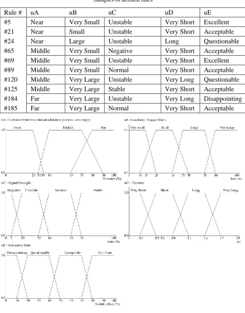
Table 1, summarizes the fuzzy input and output parameters. Each input parameter is converted into terms defined in the corresponding fuzzy set by a membership function. The inference engine deduces the output term using defined rules. The fuzzy rule table contains combinations of all input and output terms. Therefore, our inference logic is based on a total of 192 individual rules. Some characteristic samples of these rules are listed in Table 2. The samples show the effect of each input variable on the output. In the proposed design, the logical factors have a greater effect on the output than the physical factors. This design is based on the influence that each factor has on the communication QoS. Physical factors are relatively easy to control, i.e., users can move closer to the base station if required, and the signal strength can be adjusted (not recommended for power saving and safety purposes). However, it is difficult to control the logical factors. The result generated by the inference engine is converted into a crisp value by a membership function. This output is the estimated link state. The membership functions used in the above-mentioned processes are illustrated in Figure 5. There are various methods for obtaining the inferred result and its crisp output. We apply the most popular method used in fuzzy-based studies, i.e., the rule-based reasoning of Mamdani’s min-max method. The defuzzification result is obtained using the center of gravity [16].
Table 2 Samples of defined rules
Rule # uA uB uC uD uE
#5 Near Very Small Unstable Very Short Excellent
#21 Near Small Unstable Very Short Acceptable
#24 Near Large Unstable Long Questionable
#65 Middle Very Small Negative Very Short Acceptable
#69 Middle Very Small Unstable Very Short Excellent
#89 Middle Very Small Normal Very Short Acceptable
#120 Middle Very Large Unstable Very Long Questionable
#125 Middle Very Large Stable Very Short Acceptable
#184 Far Very Large Unstable Very Long Disappointing
#185 Far Very Large Normal Very Short Acceptable
Figure 5
Membership functions for input and output parameters
3.2 Adaptive Control of Snooping Buffer Size
As discussed in Section 2.1, TCP is the most widely used protocol in communication environments. However, conventional TCP is optimized to
support communication over-wired networks. A number of researches have suggested variants to extend its applicability, with snooping-based TCP suggested for wireless networks. The key features of the snooping mechanism are the packet capture and analysis functions. Thus, the buffer is the most important resource for the snooping module. This study adopts an adaptive scaling policy for the size of the snooping buffer of each flow. Figure 5 describes the process of buffer size rescaling.
Figure 5
Process of adaptive buffer rescaling
The process between measuring the link state and obtaining the current state corresponds to the fuzzy-based estimation described in Section 3.1. The rescaling process starts by comparing the current state with the historical state. The historical state is used to identify the trend in state changes. Thus, a range of historical states can be included. In this study, the historical state indicates the center of gravity of the previous three phases. The comparison result is converted to the state score, and this is utilized in the rescaling policy. The policy works to reduce the size of the allocated buffer when the condition continues to worsen, and vice versa.
The snooping buffer is a finite resource with a limited capacity for storage. Thus, the rescaling policy must consider the available capacity and utilization of the snooping buffer. If the buffer utilization is low, the utilization must be increased by allocating more space for flows that are improving. In contrast, additional allocation should be avoided if the buffer has a high utilization rate. Figure 6 presents these rescaling rules in two tables. Each table illustrates the decision- making process of the buffer rescaling for the given conditions.
In Figure 6, we do not specify the magnitude of the change in buffer size, as this can be changed according to the features, circumstances, and conditions of the network. In this study, we apply a small differential to increase or decrease the size depending on the state score and buffer utilization. However, the difference is only a few packets.
Figure 6
Rules for adjusting buffer size
This rescaling policy increases the circulation speed of the buffer. Thus, this scheme provides more space to links that can discard packets rapidly. It is difficult to predict and formalize the change in the link state, so we assume that the pattern of change is similar to a mathematical curve such as a sine or cosine wave. This curve is assumed to reflect the changes in transmission rate. The fixed buffer size can then be represented by the horizontal line. When the curve is located above the buffer size, there has been a failure to take full advantage of the transmission rate. The opposite situation indicates a transmission delay in the buffer, which is referred to as a bottleneck. Delayed packets can be transferred from the buffer when the transmission rate has been restored. This situation leads to an overall delay in transmission. The proposed scheme regulates the buffer size in accordance with this curve. Although these adjustments cannot exactly match the curve, they assist in minimizing inefficient movements.
4 Simulation Design and Results
We conducted simulations to evaluate the effectiveness of the proposed model.
The operation of communication can be expressed as a discrete event, and each operation and device has a specific state corresponding to that event. Therefore, we adopted the DEVS methodology [17, 18] for our analysis.
4.1 Simulation Design
Figure 7, shows a schematic of our simulation model. The model was designed according to the configuration shown in Figure 1. Most of the modules shown in Figure 7 were used to simulate the physical device; only the wireless link module was used to simulate the environment. In addition, there was no module for wired links in the overall structure because our study is focused on problems in wireless communication. Thus, we included a separate module to simulate errors occurring in wireless links.
Figure 7
Schematic of wireless flow simulation
The fixed host transmits a packet when the mobile host requests data. In this process, the base station controls the overall flow for packet transmission. The flow monitor plays the most important role in the base station, i.e., managing the packet flow for communication links. For this purpose, the flow monitor receives incoming packets and analyzes the flow. This analysis is based on fuzzy logic, as discussed in Section 3. The estimated state determines the snooping mode to be applied to the link. The base station sends the received packet to the destination host. If the snooping mode is activated, the flow monitor temporarily stores the packet in the buffer. The stored packet is used for local retransmission to correct transmission errors. Therefore, if the acknowledgment packet is received, the base station discards the packet stored in the buffer. The flow monitor then requests the next packet to fill the empty space in the buffer. The mobile host simulates the movement and operation of a handheld device using a map.
Figure 8 shows a virtual load map for simulating the node mobility of the mobile host. Originally, we planned to conduct simulations using a real roadmap.
However, we decided to use a virtual map because of problems with the road and base station locations. The map shows a virtual terrain in 7 × 7 grid form, with four base stations. The map has an infinite loop structure, i.e., its opposite ends are connected. All edges represent movement paths of nodes in the grid map. We designed the node mobility model on the basis of the Manhattan model [19, 20].
The dotted circles in the figure represent the coverage area of each base station.
The nodes in overlapping coverage areas have to select a base station for communication. A mobile device generally connects to a base station depending on the signal strength. Thus, the handover situation arises when the base station communicating with the node changes. However, this simulation does not consider the handover situation. Therefore, we simplified the event generated at the point of handover. Every node selects a base station that has a clear advantage in terms of signal strength.
Figure 8
Virtual map for node mobility simulation
The simulation settings were as follows. The fixed host provided all data services from a single module. The base station and the mobile host constituted a single physical module. However, these modules acted as multiple devices through internal objects. The base station module set up each virtual device using four objects. The behavior of the base station was implemented through the method and operation of the objects, whereas handover was implemented as a data exchange between the objects. The mobile host module represented individual nodes through 128 objects. Every node sent a packet and updated its current position. We applied the Manhattan model to implement node mobility. The behavior design for communication was based on data collected from wireless routers. In this process, we also referred to the Wikipedia page traffic statistics [21].
4.2 Results and Discussion
Through our simulations, we compared three metrics for three models. The first model represents normal TCP communication without the snooping scheme (N- TCP) [22, 23]. The second model represents indirect TCP communication with the typical snooping scheme (S-TCP) [8], and the third model represents the snooping TCP mechanism for adaptive flow QoS control (AFQ-TCP). A description and the measurement results of each model are presented in the following subsections.
4.2.1 Total Number of Packets Generated
Figure 9
Total number of packets generated
The first metric is the total number of packets generated. A packet is a transmission unit for exchanging data and control messages. The number of packets generated from the same data is closely related to the frequency of error recovery. Therefore, an increase in the number of packets indicates inefficiency in the error recovery scheme. This also degrades the communication efficiency owing to the increase in network traffic. Figure 9 shows the number of packets generated for each model for 10,000 discrete events. The generated packets may include both data and control packets from each model.
As shown in Figure 9, N-TCP produced the largest number of packets because it does not include any scheme for wireless environments. Both snooping-based models used fewer packets than N-TCP. However, the proposed model displayed a slight advantage over S-TCP. Although the proposed model and S-TCP are based on the same snooping technique, the former includes adaptive schemes with fuzzy logic and buffer management; in addition, AFQ-TCP controls the packet flow according to the link state.
A bad link receives fewer opportunities to control packet flow based on buffer size management. Thus, this adaptive scheme is responsible for the difference in performance.
4.2.2 Total Communication Time
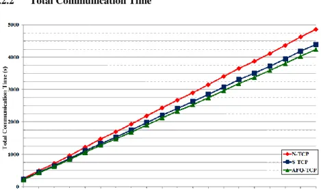
Figure 10 Total communication time
The second metric is the total communication time, i.e., the time taken for data transmission. The total communication time is a measure of the simulation time for each model. We deployed the same dataset and communication behavior for this measurement. The main factors that affect the communication time are packet error and the processing time of the control schemes. Therefore, an increase in the communication time indicates inefficiency in the control scheme. Figure 10 shows the total communication time for each model for 10,000 discrete events. For this measurement, we adjusted the simulation time ratio to be as high as possible. This is because we faced some problems in measuring the runtime without scaling the ratio.
Figure 10 indicates there was a notable gap between the runtimes of the three models as the simulation progressed. This gap is associated with delays due to transmission errors. N-TCP performs a recovery operation from a fixed host to the mobile host to correct transmission errors. In contrast, snooping-based techniques can correct packet errors at the base station. Thus, snooping-based TCP performs faster retransmission than N-TCP.
Our model provides additional communication cycles and resources according to the link state. The base station has limited resources, and S-TCP utilizes the resources evenly for each link in the snooping cycle. Our model does not guarantee a uniform distribution of resources to links. Instead, our scheme speeds up the transfer by focusing on and selecting excellent links. As a result, the communication time of the proposed model was observed to be faster than that of S-TCP.
4.2.3 Throughput
0.5 0.51 0.52 0.53 0.54 0.55
500 1000 1500 2000 2500 3000 3500 4000 4500 5000 5500 6000 6500 7000 7500 8000 8500 9000 9500 10000 N-TCP S-TCP AFQ-TCP
Simulation Event Count
Throughput
Figure 11 Throughput
s a s a
x
X
X ) (
) (
(1)
The third metric is the throughput. This was calculated using equation (1), where T denotes the throughput, Tx denotes the throughput of the x-th node, Ps denotes the total number of packets generated, Ps(x) denotes the Ps of the x-th node, Pa denotes the number of successfully delivered packets, and Pa(x) denotes the Pa of the x-th node. Thus, the throughput is obtained by dividing the number of successfully delivered packets by the total number of packets generated. Higher throughput can be achieved by using fewer packets for packet transmission, or by reducing packet loss. In other words, high throughput indicates an efficient flow control scheme. Figure 11 shows the throughput for each model for 10,000 discrete events.
As shown in Figure 9, N-TCP generated a greater number of packets than the other models. Therefore, N-TCP exhibited the lowest throughput among the three models. The difference between S-TCP and our model is attributable to their respective snooping policies. The snooping module of S-TCP only supports the enabled or disabled protocol for each link. However, the proposed model regulates
the snooping cycle in accordance with the link state. This minor difference has a significant impact on the throughput. Thus, the proposed model displayed a higher throughput.
Conclusions
We have presented a model for adaptive flow QoS management to overcome the problems suffered by conventional networking in wireless environments.
Specifically, we have developed a link state estimation method based on fuzzy logic, and designed an adaptive flow control method based on the estimated link state. This approach allows the proposed scheme to increase the communication efficiency by providing greater opportunities to better links. We conducted simulations to evaluate the performance of the proposed model. The simulation results showed that the proposed model improves the efficiency of wireless communication, as it requires fewer packets and less communication time and provides high throughput.
In future work, we will attempt to regulate the proposed scheme. The short-term objective is to design a method for sharing the collected packets between base stations. The present study does not address this issue in detail. Instead, we have simply assumed that all base stations use the virtual shared repository within the simulation constraints. The long-term objective is to conduct experiments using realistic terrain and base station placements.
Acknowledgement
This work was supported by Defense Acquisition Program Administration and Agency for Defense Development under the contract UD140022PD, Korea, and funded by the Ministry of Science, ICT and Future Planning (NRF- 2013R1A1A3A04007527).
References
[1] Raychaudhuri, D. & Mandayam, N. B.: Frontiers of Wireless and Mobile Communications, Proceedings of the IEEE, Vol. 100, No. 4, pp. 824-840, 2012
[2] Agrawal, D. & Zeng, Q. A.: Introduction to Wireless and Mobile Systems, Cengage Learning, 2015
[3] Avestimehr, A. S., Diggavi, S. N., & Tse, D. N.: Wireless Network Information Flow: A Deterministic Approach, Information Theory, IEEE Transactions on, Vol. 57, No. 4, pp. 1872-1905, 2011
[4] Maisuria, J. V. & Patel, R. M.: Overview of Techniques for Improving QoS of TCP over Wireless Links, In Communication Systems and Network Technologies (CSNT), 2012 International Conference on. IEEE, pp. 366- 370, 2012
[5] Dalal, P., Kothari, N., & Dasgupta, K. S.: Improving TCP Performance over Wireless Network with Frequent Disconnections, International Journal of Computer Networks & Communications, Vol. 3, No. 6, pp. 169-184, 2011
[6] Liu, C. P.: Adaptive Splitting TCP for Wireless Sensor Networks, International Journal of Engineering and Industries (IJEI), Vol. 2, No. 2, pp. 88-94, 2011
[7] Le, D., Fu, X., & Hogrefe, D.: A Cross-Layer Approach for Improving TCP Performance in Mobile Environments, Wireless Personal Communications, Vol. 52, No. 3, pp. 669-692, 2010
[8] Nguyen, T. H., Park, M., Youn, Y., & Jung, S.: An Improvement of TCP Performance over Wireless Networks, In Ubiquitous and Future Networks (ICUFN), 2013 Fifth International Conference on. IEEE, pp. 214-219, 2013 [9] Tiyyagura, S., Nutangi, R., & Reddy, P. C.: An Improved Snoop for TCP Reno and TCP Sack in Wired-Cum-Wireless Networks, Indian Journal of Computer Science and Engineering (IJCSE), 2, pp. 455-460, 2011
[10] Rajasekaran, S. & Pai, G. V.: Neural Networks, Fuzzy Logic and Genetic Algorithms, PHI Learning Private Limited, 2011
[11] Sethis, K., Kole, A., & Bhattacharya, P. P.: Adaptive Fuzzy Logic-based QoS Management in Wireless Sensor Network, Advanced in Electronics and Electrical Engineering (AEEE), 2013 International Conference on, pp.
72-76, 2013
[12] Munir, S. A., Bin, Y. W., Biao, R., & Jian, M.: Fuzzy Logic-based Congestion Estimation for QoS in Wireless Sensor Network, In Wireless Communications and Networking Conference (WCNC), 2007 International Conference on IEEE, pp. 4336-4341, 2007
[13] Teppala, K. & Kumar, K.: A Fuzzy Logic Control in Distributed Traffic Management for Efficient Networks, International Journal of Scientific Engineering and Technology Research, Vol. 3, No. 48, pp. 9788-9793, 2014
[14] Khoukhi, L. & Cherkaoui, S.: Experimenting with Fuzzy Logic for QoS Management in Mobile ad hoc Networks. International Journal of Computer Science and Network Security, Vol. 8, No. 8, pp. 372-386, 2008 [15] Collotta, M. & Scatà, G.: Fuzzy Load Balancing for IEEE 802.11 Wireless
Networks, IERI Procedia, Vol. 7, pp. 55-61, 2014
[16] Lee, C. C.: Fuzzy Logic in Control Systems: Fuzzy Logic Controller. II.
Systems, Man and Cybernetics, IEEE Transactions on, Vol. 20, No. 2, pp.
419-435, 1990
[17] Zeigler, B. P.: Hierarchical, Modular Discrete-Event Modeling in an Object-oriented Environment, Simulation, Vol. 49, No. 5, pp. 219-230, 1987
[18] Zeigler, B. P., Moon, Y., Kim, D., & Ball, G.: The DEVS Environment for High-Performance Modeling and Simulation, Computing in Science and Engineering, Vol. 4, No. 3, pp. 61-71, 1997
[19] Lim, S., Yu, C., & Das, C. R.: Clustered Mobility Model for Scale-Free Wireless Networks, In Local Computer Networks, Proceedings 2006 31st IEEE Conference on. IEEE, pp. 231-238, 2006
[20] Lenders, V., Wagner, J., Heimlicher, S., May, M., & Plattner, B.: An Empirical Study of the Impact of Mobility on Link Failures in an 802.11 ad hoc network, Wireless Communications, IEEE, Vol. 15, No. 6, pp. 16-21, 2008
[21] Wikipedia Page Traffic Statics, https://aws.amazon.com/items/2596, 2009 [22] Padhye, J., Firoiu, V., Towsley, D. F., & Kurose, J. F.: Modeling TCP
Reno Performance: a Simple Model and its Empirical Validation, IEEE/ACM Transactions on Networking (ToN), Vol. 8, No. 2, pp.133-145, 2000
[23] Khan, M. N. I., Ahmed, R., & Aziz, M.: A Survey of TCP Reno, New Reno and Sack over Mobile ad-hoc Network, International Journal of Distributed and Parallel Systems (IJDPS), Vol. 3, No. 1, pp.49-63, 2012