DOI: https://doi.org/10.14232/analecta.2020.2.61-68 61
BEHAVIOR OF THE STRUCTURE OF DIFFERENT MATERIALS UNDER STATIC FORCE
1Balázs P. Szabó, 1Zita Zakupszki, 2Balázs Szabó
1 University of Szeged, Faculty of Engineering, Department of Food Engineering, 6725 Moszkvai krt. 5-7., Szeged, Hungary
2 University of Szeged, Faculty of Dentistry, Department of Periodontology, 6720 Tisza Lajos krt. 64., Szeged, Hungary
*e-mail: szpb@mk.u-szeged.hu
Received: August 13, 2020 • Accepted: October 29, 2020
ABSTRACT
The subject of rheology is the study of force-induced deformation and creep in materials, taking into account the effect of time too. The purpose of the measurements is to study time-dependent tension-deformation correlations, which include creep and tension-relaxation parameters, and viscosity. Due to the characteristic structure of biological materials, we try to introduce rheology through different materials. Our samples also include soft, semi-hard and hard materials from fish meat to human teeth. It is very clear from the obtained results that the internal structure of each material is influenced by many factors. These factors also interact with each other and they cannot be standardized in a single study.
Keywords: rheological tests, viscoelastic material, mechanical fracture test 1. INTRODUCTION
Relatively many experiments have been performed in the recent past to understand/evaluate the physical as well as mechanical properties of different materials. These studies included the study of the relationships between load-deformation and tension-relative elongation, the cases of pressure, tensile, shear, bending and hydrostatic compression, supplemented by the studies required for the viscoelastic characterization of materials. During the tests, the status indicators, which are influencing the mechanical properties are included as variables (Sitkei 1981, Mohsenin 1968).
In the study of materials, the correlations between force and deformation are most often examined. The load can be applied with a cylindrical pressure head, a spherical head and a flat slab. It is assumed that the steel load heads can be considered rigid with respect to the examined material, so they do not deform (Rosenthal 1999). The elasticity factor E, the biological pour point, the breaking point and the Poisson’s ratio can be determined from the force-deformation correlations. During the measurements, the various status indicators of the material must be accurately recorded.
A striking feature of biological materials is that the correlation of force-deformation also depends on the rate of deformation. This means that the correlation should be sought between three factors rather than between two factors (tension and deformation). Materials where we also have to take into consideration the effect of time are called viscoelastic materials. These substances have the properties of partly solids and partly of liquids (Peleg 1982). For some materials, the relatively small loads result in tension and deformation, which are only dependent from the amount of time, but does not show correlation with the tension. Such materials are called linear viscoelastic materials (Ferry 1980). For many materials, when a significant amount of the deformation caused by loading cannot be recovered during unloading, the tension-deformation correlation depends not only on time, but also on the magnitude of the tension. In this case we speak of non-linear viscoelasticity. For synthetic models that illustrate the theoretical results of rheology, „rheological bodies” embodying the basic forms of mechanical behavior were introduced as basic models: The behavior of elastic materials is comparable to that of a spring, while the properties of fluids are similar to those of damping element. Accordingly, the behavior of viscoelastic materials can be formed by a coupling combination of these two phenomes switches. It can be serial (Maxwell model) and
DOI: https://doi.org/10.14232/analecta.2020.2.61-68 62
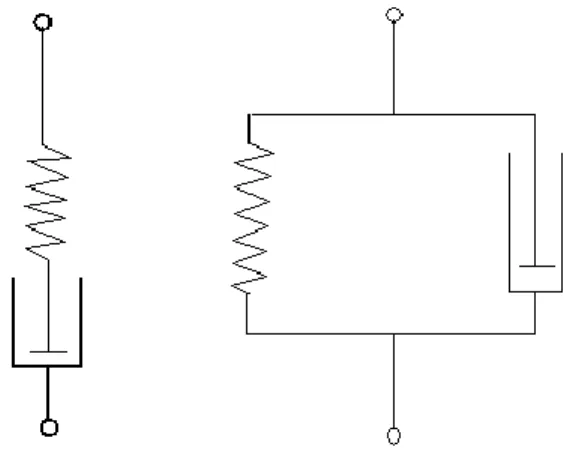
parallel (Kelvin model) (Figure 1). By connecting two rheological bodies in parallel, we mean that the deformation of the bodies is the same, and the uptake of the deformation tension is shared by the two bodies according to their resistance. By serial connection of the two bodies is meant that the deforming tension acts on both bodies with its total value, and the total deformation of the coupled pair is the sum of the deformations of the two bodies.
Figure 1. Schemas of the Maxwell model and the Kelvin model
The deformation of a viscous body or Maxwell’s body (b) (according to the assumptions of the so-called linear viscosity) is constant under constant tension and increases at a rate proportional to the tension. This is described by the equation below:
dt k
d
(1)where k is a constant characterizing the viscosity of the material.
2. MATERIAL AND METHODS
One of the most important properties of materials is their hardness, which exerts against the penetration of a rigid material. Two groups of processes are known, the classical method, in which the measurement is performed by creating a deformation, and methods based on other physical action. The latter includes, for example, the impact test method or the acoustic stock test.
Classical methods for measuring deformation can be grouped according to the method of inducing the deformation (quasi-static or dynamic methods), the method of measuring the deformation due to external influence (measuring the diameter, which is determining the surface of the print), the indentation depth, and in terms of the design of the measuring instrument. In terms of the design of the measuring device can be a manual, portable or fixed measuring device with a desktop by stand arrangement – simple, with manual or automatic operation with computer (or PLC) control, or automatic evaluation using an image processing method (Steffe 1996).
In our work we present the results of such static measurements. In our studies, we have a number of measurements regarding their hardness, from various foods to human teeth, of which we highlight only a few in the course of this current work.
DOI: https://doi.org/10.14232/analecta.2020.2.61-68 63
The principle of quasi-static measurement is that during the measurement a hard body (measuring head) of standard material, shape and size is pressed on / into the surface of the material to be measured with load acting for a certain time. The load is slowly increased, which is why the methods are called quasi-static or static hardness measurements. Its schematic drawing is shown in Figure 2.
Figure 2. Deformation of samples under load
For most of the tests, the force is usually transmitted by a cylindrical measuring head, which has a circular cross-section. The resulting compressive tension can be calculated from the F force and the A surface of the measuring head
𝜎 = 𝐹/𝐴 (2)
It is advisable to calculate and apply the relative deformation instead of deformation:
𝜀 = Δ𝑙/𝑙 (3)
Where: the original size of the raw material tested:
before deformation: lo
after deformation: l - l
According to Hooke’s law, the E modulus of elasticity (Young’s modulus of elasticity) establishes a relationship between the above quantities:
𝜎 = 𝐸 ∙ 𝜀 (4)
Materials that can be described by Hooke’s law are called flexible materials. If a load greater that the destruction limit is applied, macroscopic damage is going to occur on that sample.
Our tests were performed with the Lloyd 1000R Material Testing Machine (Figure 3).
The device operates on uniaxial pressure (load mode). During experiments the device must meet the following requirements in order to obtain usable results:
o the load must be exactly axial so that no bending effect occurs,
o minimizing friction between the end plate and the pressure plate of the measuring head so that the transverse elongation of the measuring head is not limited,
o such a length-to-diameter ratio must be selected in which the risk of buckling does not yet exist.
DOI: https://doi.org/10.14232/analecta.2020.2.61-68 64
Figure 3. Lloyd 1000R Material Testing Machine
The device perfectly shows the compressive force given to the material as a function of the distance travelled by the measuring head. The machine records the data during the measurement and draws the force-displacement curve in a coordinate system (displacement in mm on the x-axis, force in N on the y- axis). Based on the data, we can immediately see the amount of force that the given material can no longer withstand and it is going to break. Depending on the values of 0 N and maximum N in the graph and the path length assigned to them, we can determine the maximum force which is required to break the material, hereinafter referred to as the breaking force, and the associated breaking work which is determined by the area under the curve. We can determine the deformation modulus from the force-displacement curve. For the measurements, the measuring head, the speed and the height change must be set (Lloyd Instruments 1991).
3. RESULTS AND DISCUSSION
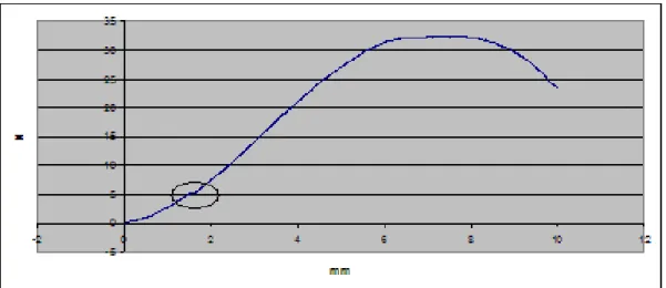
In our studies, we encountered different curves (described above) that nicely showed the relationship with the structure of the material. In the case of agricultural materials, it is clear from Figure 4 (wheat) that the material has a so-called biological pour point (circled in the figure). This is the point on the force- displacement (tension-deformation) curve from where the tension decreases or remains constant as the deformation increases. This point indicates that an initial fracture occurs in a small volume of the cell system. Therefore below this point the structure has not changed yet, but above this point even if it is not visible to the eye, the structure of the material is already damaged.
DOI: https://doi.org/10.14232/analecta.2020.2.61-68 65
Figure 4. The force-displacement curve of wheat
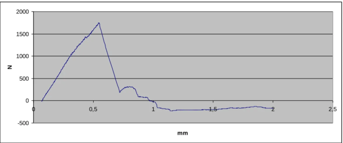
By looking at the course of the curve, after the previously mentioned point we reach the breaking point (maximum breaking force). This point is the point on the force-displacement (tension-deformation) curve where the tension decreases sharply and significantly as the deformation increases. This point indicates that a significant volume of the material fractured. The curve shows that this point is reached steeply, over a very short exposure range (~0,5mm), thus we are dealing with a rigid, hard material. This initial, rapid ramp-up of the curve can also be characterized by the direction tangent of a more or less straight section.
This is nothing more than the modulus of elasticity, which is an excellent material characteristic figure.
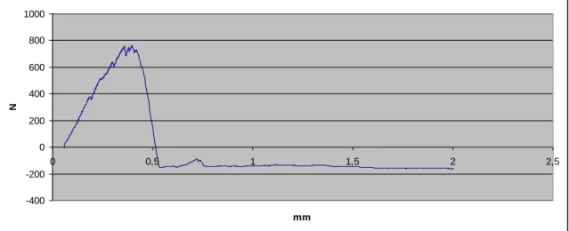
In contrast, in case of a soft, resilient material, fracture occurs after significant plastic deformation. Such a course is seen in Figure 5 (fish meat). Here it is clear that the substance has a biological pour point (circled in the figure) in the same way. Due to the nature of flexible materials, the curve shows that the maximum force required for complete fracture is reached slowly, after a long penetration distance (and does not have such a classic visible maximum breaking force), so as opposed to a hard, rigid material, the curve does not rise steeply. This elastic change can be clearly seen from the beginning of the measurement.
Figure 5. The force-displacement curve of fish meat
DOI: https://doi.org/10.14232/analecta.2020.2.61-68 66
Interesting results can be found when teeth are loaded and tested, which highly depend on the mechanical properties (elastic modulus, flexural strength, fracture toughness) of the materials used to restore the teeth, the positioning (extracoronal or intracoronal) of the restorative materials, and also the way the restorative material is luted to the dental structures, tissues. In case of correctly using the now widespread and most commonly used adhesive dentistry to restore teeth the restorative material will form a unit with the adhering dental structures and their mechanical properties will cummulate. It is important to note that both fracture resistance and the pattern of fracture will be determined by the amount of restorative material used to substitute the missing dental tissues, and also by the similarity between the mechanical features of the substituted dental tissues and the used restorative materials. Originally for a direct filling dentists use a less elastic restorative material (packable composite resin), which more resembles enamel than dentin regarding its mechanical properties. This is nicely shown by the brittleness, low fracture toughness and high wear resistance of packable composite resins. These materials rather behave as rigid materials on their own and even inside the tooth (Figure 6.). This results in unfavorable fracture pattern going through the tooth- restoration unit when of fracture occurs.
Figure 6. Curve showing a fatal, unrepairable fracture in case of restored teeth
The difference in mechanical features of different restorative materials become visible and clinically relevant when significant amount of dentin needs to be substituted during the restorative procedure (Forster et al, 2018). The reason behind this is the remarkable elasticity of dentin, leading to a unique stress- reducing and crack-arresting feature (Figure 7.) (Lassila et al, 2018). Thus it is logical that in case of severe dentinal loss the tooth can only be reinforced if the operator uses a highly elastic material to replace the missing dentin. The fracture toughness and flexural strength of new short fiber-reinforced composite materials are similar to that of dentin’s, therefore they behave as elastic materials (Lassila et al, 2018).
-500 0 500 1000 1500 2000
0 0,5 1 1,5 2 2,5
mm
N
DOI: https://doi.org/10.14232/analecta.2020.2.61-68 67
Figure 7. Curve showing the fracture resistance of an elastic materials
Many studies have shown that better results can be obtained if short fiber-reinforced composite is used rather than conventional composite resin to substitute great amount of missing dentin (Fráter et al, 2019;
Fráter et al, 2020; Forster et al, 2016). Furthermore the pattern of fracture is dominantly favorable when using fiber-reinforced composite, meaning the fibers first absorb, then dissipate and redirect the stress in the form of crack and/or fracture towards the surface of the tooth (Figure 8.) (Fráter et al, 2014; Sáry et al, 2020).
Figure 8. Curve showing the fracture resistance of a tooth restored with short fiber-reinforced composite 4. CONCLUSIONS
Our studies have shown that whatever living matter is used during the mechanical examination, their structure can behave in many different ways under the influence of mechanical action. This behavior is influenced by a number of factors. These factors can also strengthen or weaken each other. In the case of an agricultural material, in addition to the factors influencing the basic structure (e.g.: variety/type),
-200 0 200 400 600 800 1000 1200 1400 1600 1800
0 0,5 1 1,5 2 2,5
mm
N
-400 -200 0 200 400 600 800 1000
0 0,5 1 1,5 2 2,5
mm
N
DOI: https://doi.org/10.14232/analecta.2020.2.61-68 68
weather, vintage, and fertilization also appear. In case of testing restored teeth the results can be influenced by the medium in which the teeth were kept, cracks and fractures occuring in the teeth before or during extraction, and the age of the tooth (Szabó et al, 2019; Szabó P et al, 2019). Unfortunately not all factors can be standardized during a test like this. In clinical practice all factors which influence the structures of dental hard tissues (developmental diseases of enamel or dentin, the age of the patient, extreme mechanical impact or biting force) can alter the mechanical behavior of the restoration-tooth unit.
REFERENCES
[1] Ferry J.D. (1980): Viscoelastic Properties of Polymers. Wiley New York
[2] Forster A, Braunitzer G, Tóth M, Szabó B.P., Fráter M. (2019): In Vitro Fracture Resistance of Adhesively Restored Molar Teeth with Different MOD Cavity Dimensions. J Prosthodont., 2019
[3] Forster A, Sáry T, Braunitzer G, Fráter M. (2016): In vitro fracture resistance of endodontically treated premolar teeth restored with a direct layered fiber-reinforced composite post and core. J Adhes Sci Technol. 2016;31:1454–
66.
[4] Fráter M, Forster A, Keresztúri M, Braunitzer G, Nagy K. (2014): In vitro fracture resistance of molar teeth restored with a short fibre-reinforced composite material. J Dent., 2014, 42(9):1143-50.
[5] Fráter M, Lassila L, Braunitzer G, Vallittu P.K, Garoushi S. (2019): Fracture resistance and marginal gap formation of post-core restorations: influence of different fiber-reinforced composites. Clin Oral Investig. 2020, 24(1):265-276.
[5] Fráter M, Sáry T, Néma V, Braunitzer G, Vallittu P, Lassila L, Garoushi S. (2020): Fatigue failure load of immature anterior teeth: influence of different fiber post-core systems. Odontology, 2020
[6] Lassila L, Keulemans F, Säilynoja E, Vallittu P.K., Garoushi S. (2018): Mechanical properties and fracture behavior of flowable fiber reinforced composite restorations. Dent Mater. 2018, 34(4):598-606.
[7] Lloyd Instruments (1991):Materials testing machines, Operating instructions, Copyright: Lloyd Instruments Limited
[8] Mohsenin N (1968): Physical Properties of Plant and Animal Materials, Gordon and Breach [9] Peleg M, Bagley E.B. (1982): Physical Properties of Food. AVI Publishing, Westport
[10] Rosenthal A.J. (1999): Food Texture, Perception and Measurement. Aspen Publishers Gaithersburg, 89 p.
[11] Sáry T, Garoushi S, Braunitzer G, Alleman D, Volom A, Fráter M. (2019): Fracture behaviour of MOD restorations reinforced by various fibre-reinforced techniques - An in vitro study. J Mech Behav Biomed Mater, 2019
[12] Sitkei Gy. (1981): Mezőgazdasági anyagok mechanikája, Akadémiai Kiadó, Budapest
[13] Steffe J.F. (1996): Rheological Methods in food Process Engineering, 2nd ed. Freeman Press, East Lansing.
[14] Szabó B, Garoushi S, Braunitzer G, Szabó P.B, Baráth Z, Fráter M. (2019): Fracture behavior of root-amputated teeth at different amount of periodontal support – a preliminary in vitro study. BMC Oral Health. 2019, 19(1):261.
[15] Szabó P.B, Sáry T, Szabó B. (2019): The key elements of conducting load-to-fracture mechanical testing on restoration-tooth units in restorative dentistry. Analecta Technica Szegedinensia. 2019 Vol. 13, No. 2.